Download presentation
Presentation is loading. Please wait.

1
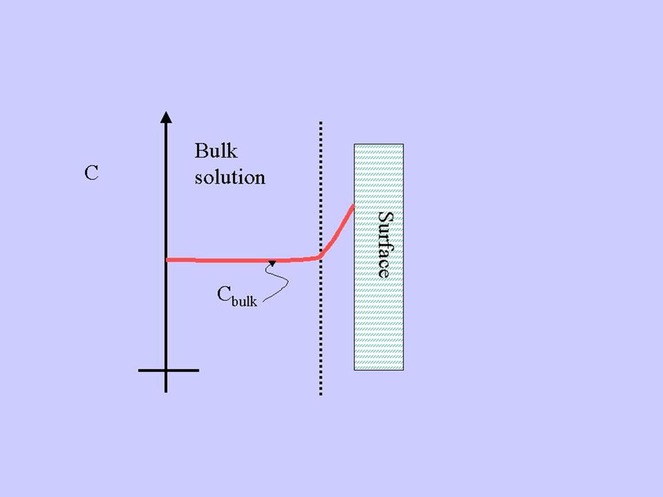
ADSORPTION Adsorption is the process in which matter is extracted from one phase and concentrated at the surface of a second phase. (Interface accumulation). This is a surface phenomenon as opposed to absorption where matter changes solution phase, e.g. gas transfer. This is demonstrated in the following schematic.
. This is a surface phenomenon as opposed to absorption where matter changes solution phase, e.g. gas transfer. This is demonstrated in the following schematic.")
2
d

3
If we have to remove soluble material from the solution phase, but the material is neither volatile nor biodegradable, we often employ adsorption processes. Also adsorption has application elsewhere, as we will discuss later. adsorbate: material being adsorbed adsorbent: material doing the adsorbing. (examples are activated carbon or ion exchange resin).
.")
4
Surface Energy An explanation of why material accumulates at the interface is based on the excess energy associated with particles at interfaces. For example, in the case of pure water and air, the water molecules at the air-water interface have higher energy than water molecules in the interior of the water phase. The reason that these surface molecules have higher energy is that, unlike the interior molecules, they have an unbalanced force component (on the airside of the molecule).
.")
5
These surface molecules have additional energy to balance the forces
These surface molecules have additional energy to balance the forces. It takes energy to put molecules on the surface, since at least one of the interior bonds must be broken to get the molecule to the surface. This excess energy is called surface tension. Since it takes energy to create interfacial surfaces, the system will try to minimize the total interfacial surface area. Hence we see spherical droplet, meniscus etc.

6
Thermodynamics of surface adsorption
In solutions certain particles tend to concentrate at the surface. These particles are those that have low affinity for the water (solvent). These are hydrophobic molecules. Because they have low affinity for the solvent the can get to the surface easily since they have low bond energy in the bulk phase. The water system prefers to have these molecules at the surface because the placement at the surface requires less energy than a water molecule -- hydrophobic molecules decrease surface energy (surface tension) relative to a pure water system.
. These are hydrophobic molecules. Because they have low affinity for the solvent the can get to the surface easily since they have low bond energy in the bulk phase. The water system prefers to have these molecules at the surface because the placement at the surface requires less energy than a water molecule -- hydrophobic molecules decrease surface energy (surface tension) relative to a pure water system.")
7
On the other hand if a particle has a high affinity for the solvent phase (hydrophilic) it will tend to remain in the bulk solution because of its strong bond with water. In fact, this bonding makes the water bonding stronger and, therefore, there is a larger energy required to get water molecules to the surface-- therefore, hydrophilic molecules increase surface tension, e.g. salts such as NaCl. As particles concentrate at surface there becomes a "surface excess". Surface excess is defined as G.

8
There are several ways to look at surface excess
There are several ways to look at surface excess. One is to view it as the amount of solute adsorbed at the surface per unit surface area in excess of bulk concentration (units = moles/cm2). As shown in this figure this "surface excess" could be viewed as a concentration in a small volume near the surface.
. As shown in this figure this surface excess could be viewed as a concentration in a small volume near the surface.")
10
Surface excess can be defined as:

11
Where "Volume" is the volume of the solution from which the adsorption is occurring onto the surface with total surface area = "surface area". Surface excess is defined as the mass adsorbed per surface area. A more fundamental definition is given by the Gibbs relationship.

12
where: mi = the molar free energy of solute i
where: mi = the molar free energy of solute i. Ci is the bulk concentration of this solute. The Gibb’s expression simply uses G as a proportionality constant to relate the change in solute molar free energy to surface tension (g) during adsorption. The underlying principle here is that for the adsorption process changes in the sum of all solute free energy must be accounted for in changes in the surface tension during the adsorption process.
 during adsorption. The underlying principle here is that for the adsorption process changes in the sum of all solute free energy must be accounted for in changes in the surface tension during the adsorption process.")
13
For a single solute:

14
results in increases in G (surface concentration)
Therefore: results in increases in G (surface concentration) results in decrease in G
 results in decrease in G.")
15
Types of adsorption: 1)Lack of solvent-solute interactions (hydrophobicity –surfactants) 2)Specific solid-solute interaction
Lack of solvent-solute interactions (hydrophobicity –surfactants) 2)Specific solid-solute interaction.")
16
Exchange adsorption (ion exchange)– electrostatic due to charged sites on the surface. Adsorption goes up as ionic charge goes up and as hydrated radius goes down. Physical adsorption: Van der Waals attraction between adsorbate and adsorbent. The attraction is not fixed to a specific site and the adsorbate is relatively free to move on the surface. This is relatively weak, reversible, adsorption capable of multilayer adsorption.

17
Chemical adsorption: Some degree of chemical bonding between adsorbate and adsorbent characterized by strong attractiveness. Adsorbed molecules are not free to move on the surface. There is a high degree of specificity and typically a monolayer is formed. The process is seldom reversible. Generally some combination of physical and chemical adsorption is responsible for activated carbon adsorption in water and wastewater.

18
ADSORPTION EQUILIBRIA
If the adsorbent and adsorbate are contacted long enough an equilibrium will be established between the amount of adsorbate adsorbed and the amount of adsorbate in solution. The equilibrium relationship is described by isotherms.

19
Define the following: qe = mass of material adsorbed (at equilibrium) per mass of adsorbent. Ce = equilibrium concentration in solution when amount adsorbed equals qe. qe/Ce relationships depend on the type of adsorption that occurs, multi-layer, chemical, physical adsorption, etc.

20
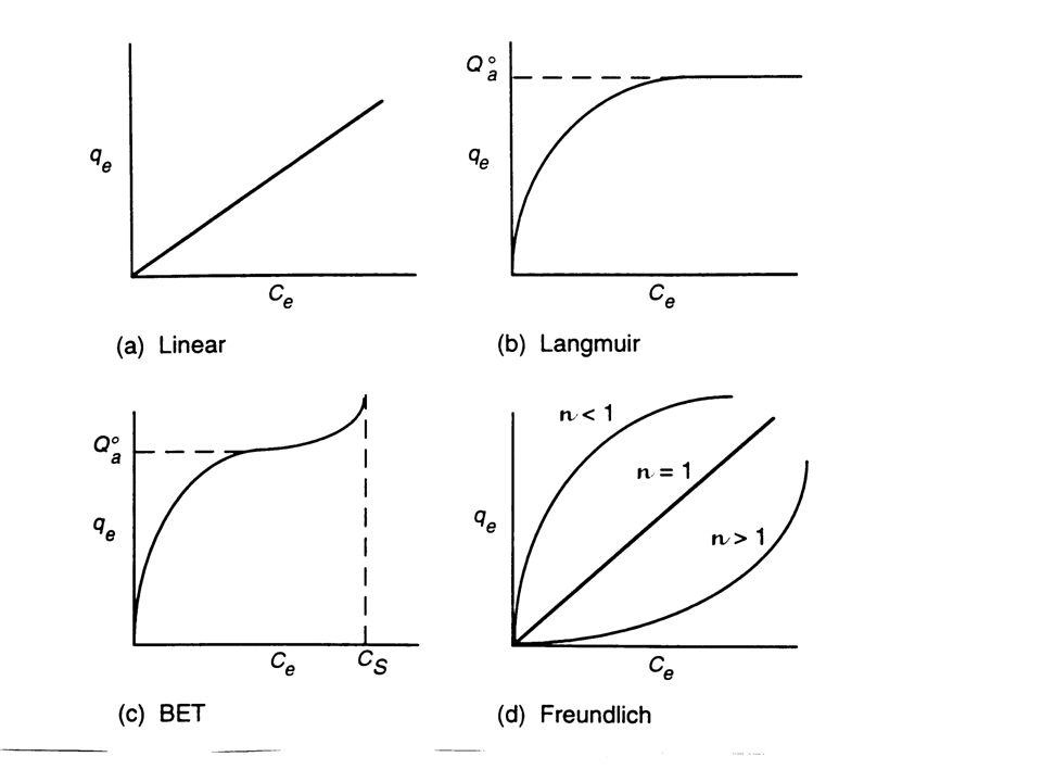
Some general isotherms are shown in the figure below.

21
Isotherm models: The figures below show that there are four common models for isotherms.

23
Langmuir Isotherm: This model assumes monolayer coverage and constant binding energy between surface and adsorbate. The model is:

24
Ce has units of mg/L. K has units of L/mg
represents the maximum adsorption capacity (monolayer coverage) (g solute/g adsorbent). Ce has units of mg/L. K has units of L/mg
 (g solute/g adsorbent). Ce has units of mg/L. K has units of L/mg.")
25
BET (Brunauer, Emmett and Teller) isotherm:
This is a more general, multi-layer model. It assumes that a Langmuir isotherm applies to each layer and that no transmigration occurs between layers. It also assumes that there is equal energy of adsorption for each layer except for the first layer.

27
CS =saturation (solubility limit) concentration of the solute
CS =saturation (solubility limit) concentration of the solute. (mg/liter) KB = a parameter related to the binding intensity for all layers. Note: when Ce << CS and KB >> 1 and K = KB/Cs BET isotherm approaches Langmuir isotherm.
 concentration of the solute. (mg/liter) KB = a parameter related to the binding intensity for all layers. Note: when Ce << CS and KB >> 1 and K = KB/Cs BET isotherm approaches Langmuir isotherm.")
28
Freundlich Isotherm: For the special case of heterogeneous surface energies (particularly good for mixed wastes) in which the energy term, “KF”, varies as a function of surface coverage we use the Freundlich model. n and KF are system specific constants.
 in which the energy term, KF , varies as a function of surface coverage we use the Freundlich model. n and KF are system specific constants.")
29
Determination of appropriate model:
To determine which model to use to describe the adsorption for a particular adsorbent/adsorbate isotherms experiments are usually run. Data from these isotherm experiments are then analyzed using the following methods that are based on linearization of the models.

30
For the Langmuir model linearization gives:
A plot of Ce/qe versus Ce should give a straight line with intercept :

31
and slope: Or:

32
Here a plot of 1/qe versus 1/Ce should give a
straight line with intercept 1/Qao and slope For the Freundlich isotherm use the log-log version : A log-log plot should yield an intercept of log KF and a slope of 1/n.

33
For the BET isotherm we can arrange the isotherm equation to get:
Intercept = Slope =

34
Factors which affect adsorption extent (and therefore affect isotherm) are:
Adsorbate: Solubility In general, as solubility of solute increases the extent of adsorption decreases. This is known as the “Lundelius’ Rule”. Solute-solid surface binding competes with solute-solvent attraction as discussed earlier. Factors which affect solubility include molecular size (high MW- low solubility), ionization (solubility is minimum when compounds are uncharged), polarity (as polarity increases get higher solubility because water is a polar solvent).
, ionization (solubility is minimum when compounds are uncharged), polarity (as polarity increases get higher solubility because water is a polar solvent).")
35
pH pH often affects the surface charge on the adsorbent as well as the charge on the solute. Generally, for organic material as pH goes down adsorption goes up. Temperature Adsorption reactions are typically exothermic i.e., D H rxn is generally negative. Here heat is given off by the reaction therefore as T increases extent of adsorption decreases.

36
Presence of other solutes
In general, get competition for a limited number of sites therefore get reduced extent of adsorption or a specific material.

37
Adsorbent: Virtually every solid surface has the capacity to adsorb solutes. From the wastewater/water treatment point of view activated carbon (AC) is the adsorbent of choice. AC prepared from many sources: Wood Lignite Coal Nutshells Bone
 is the adsorbent of choice. AC prepared from many sources: Wood. Lignite. Coal. Nutshells. Bone.")
38
These raw materials are pyrolyzed at high temperature under low oxygen conditions (so we don’t get complete combustion). This forms a “char”. The char is then activated by heating to 300 – 1000 oC in the presence of steam, oxygen or C02. Result: “Activated carbon” which is highly porous, micro-crystalline material which resembles graphite plates with some specific functional groups (e.g. COOH, OH)
")
39
Increasing magnification

40
Surface area of the AC is huge
Surface area of the AC is huge. Most of the surface area is interior in micro- and macropores. Typical surface area is in the range of m2/gram. Quality and hardness of the AC are a function of the starting material and the activation process.

41
Pore size distribution:
micropores: <2nm dia mesopores: 2nm to 20 nm dia macropores: > 20 nm

42
Pore size % pore volume % surface area Micro >95 Meso < 10 < 5 Macro negligible

43
Most of the surface area is in pores of molecular sized dimensions
Most of the surface area is in pores of molecular sized dimensions. This results in slower mass transfer during the adsorption process but also results in greater binding capacity of the adsorbate. Adsorption behavior is related in part to the nature of the functional groups on the carbon surface. In general carbon manufactured at: <500 oC is weakly acidic > 500 oC is weakly basic Spent AC can be regenerated at high temperatures (roughly a maximum of fifteen times).
.")
44
Adsorption Kinetics. Adsorption onto AC usually is modeled as a three consecutive step process. These steps are film transport (through the stagnant boundary layer about the AC particle); transport of the solute through the internal pores; and finally adsorption to the surface site. One or more of these steps can limit the rate of solute adsorption. In most cases the actual adsorption process does not limit the process. In some cases film transport limits and in other cases (most likely) pore diffusion limits.
; transport of the solute through the internal pores; and finally adsorption to the surface site. One or more of these steps can limit the rate of solute adsorption. In most cases the actual adsorption process does not limit the process. In some cases film transport limits and in other cases (most likely) pore diffusion limits.")
45
We can lump all the mass transport resistance terms into one term, k, and write:
k = overall mass transfer coefficient (cm/min) a = surface area of carbon per unit volume of reactor (1/cm) Ce = concentration that would be in equilibrium with actual amount of solute adsorbed, q (g/liter). C = actual concentration of solute in bulk solution. (g/liter).
 a = surface area of carbon per unit volume of reactor (1/cm) Ce = concentration that would be in equilibrium with. actual amount of solute adsorbed, q (g/liter). C = actual concentration of solute in bulk solution. (g/liter).")
46
If there is no degradation of solute on the carbon, removal from the solution phase must be accounted for by accumulation on the activated carbon. e = void volume fraction (volume of liquid/total volume of reactor) rb = bulk density of adsorbent in the reactor ( g adsorbent/total reactor volume). q = actual amount of solute adsorbed ( g/g).
 rb = bulk density of adsorbent in the reactor ( g adsorbent/total reactor volume). q = actual amount of solute adsorbed ( g/g).")
47
Define: k’ = This differential equation can be used to predict removal efficiencies for various reactor types.

48
CARBON CONTACTORS Activated carbon reactors are usually called carbon contactors because the waste stream is “contacted” with the carbon. Many times the contactor is of the columnar fluidized or fixed-bed type. Sometimes (less often) the contactor is in a slurry form. Fixed or fluidized beds have the advantage of not having to separate the carbon from the liquid stream after the contact period. Slurry systems need some sort of activated carbon removal process to separate the AC from the liquid stream.
 the contactor is in a slurry form. Fixed or fluidized beds have the advantage of not having to separate the carbon from the liquid stream after the contact period. Slurry systems need some sort of activated carbon removal process to separate the AC from the liquid stream.")
49
Packed bed (fixed carbon bed) contactors provide filtration as well as adsorption so they have to be periodically backwashed or cleaned. This is one reason why we only want to run soluble material through a contactor. Fluidized beds, however, do not filter and we can employ continuous supply of fresh carbon while removing spent carbon.

50
A typical packed (fixed) bed contactor looks like :
 bed contactor looks like :")
51
When the continuity equation is applied to a segment along the packed column we get:
(Note that this equation ignores dispersion. This is a reasonable assumption as long as Pe >1 which it usually is for these contactors)
")
52
U = superficial (approach) influent velocity (cm/min) This is computed by dividing Q by the entire cross-sectional area of the column. Z = distance from the entrance to the column (cm). All other parameters are as described previously. Note that: 2.1 is approximately the true density of the activated carbon without pore volume.
. All other parameters are as described previously. Note that: 2.1 is approximately the true density of the activated carbon without pore volume.")
53
Let’s look at the solution of this differential equation for two cases
Let’s look at the solution of this differential equation for two cases. First, consider the case where instant equilibrium is reached at every point in the column. Then consider the more realistic case where kinetic limitations exist.

54
Equilibrium approach:
First define a generalized isotherm as where: Q* = qe when Ce = C0 C0 = influent concentration.

55
r < 1 we get a favorable isotherm
r = 1 we get a linear isotherm r > 1 we get an unfavorable isotherm Comparing this generalized isotherm to a Langmuir isotherm we get:

56
This generalized isotherm simply isolates a portion of the overall isotherm.
R and Q * can be evaluated from experimental data by plotting 1/qe versus 1/Ce.

57
qe = f(C) (via an isotherm)
If we assume instant equilibrium at all points in the column, qe = f(C) (via an isotherm) by the chain rule
 (via an isotherm) by the chain rule.")
58
Then after regrouping terms:
Which is in the form of a differential equation which can be solved by the method of characteristics. For the typical boundary conditions : C = 0 @ t = 0, Z >0 (clean column at start) C Z = 0, t >0 For a favorable isotherm (r < 1) the solution is:
 C Z = 0, t >0. For a favorable isotherm (r < 1) the solution is:")
59
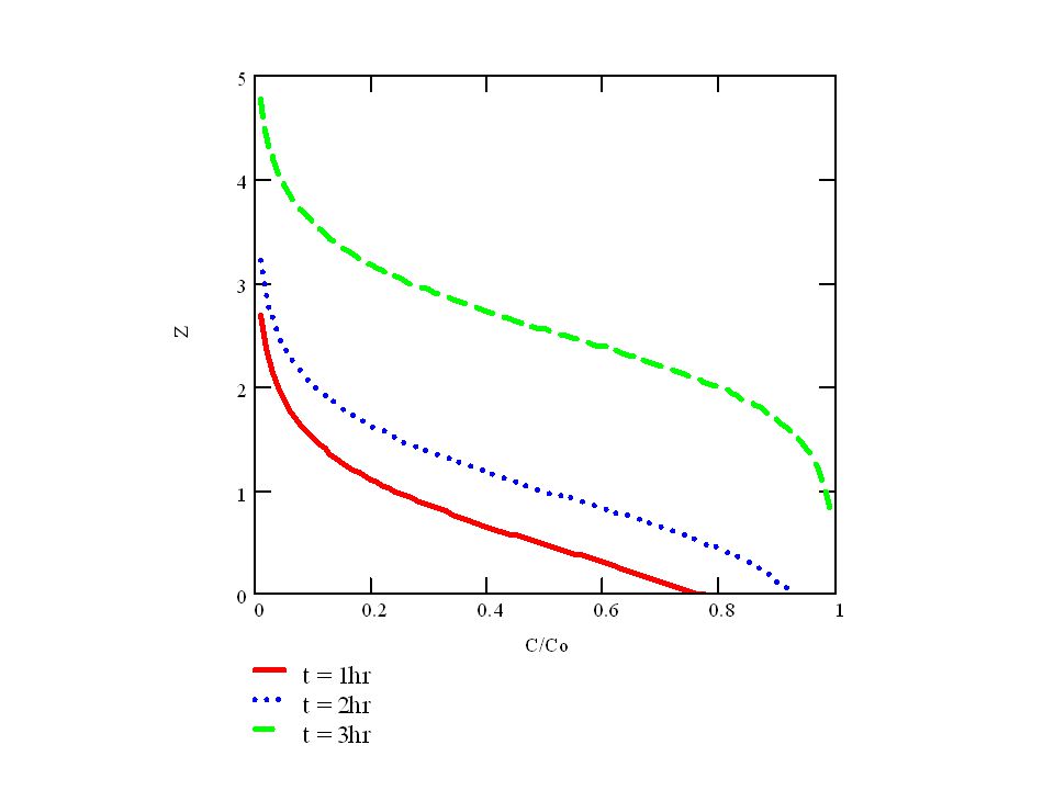
S = speed of adsorption band. (cm/min)
So the adsorption band moves through with a square wave response. A plot of effluent concentration versus time gives:

60
Time of breakthrough = Z/S

61
The breakthrough front moves through column at a speed slower than U
The breakthrough front moves through column at a speed slower than U. Solute movement is retarded by the adsorption process. The actual speed of the fluid is given by U/e. This can be compared to the speed of the solute front by rearranging the "S" equation.

62
Then as long as is greater than zero the solute will be retarded relative to the fluid velocity.

63
Kinetic Approach: Now consider the case where equilibrium is not attained, but rather there is some type of mass transfer control. For this case:

64
The generalized isotherm can be manipulated to yield:

65
After a complicated series of substitutions and integrations we end up with a solution of the following form:

66
This solution is one of “constant pattern” adsorption
This solution is one of “constant pattern” adsorption. The pattern as shown below moves through the column at a rate equal to S, but the shape of the curve remains constant. This solution requires that the “pattern” remain within the confines of the contactor. So as major breakthrough occurs the solution is inaccurate. Also at start-up the solution is inaccurate. This is generally not a problem though because the effective life of the contactor (as determined by an acceptable C/Co) would be exceeded at this point.
 would be exceeded at this point.")
69
How to use this solution to design a contactor:
Pick a C/C0 to meet effluent requirements Pick a contactor length Determine isotherm parameters from experiment. Calculate h and S From h = t –Z/S can determine the time it will take to reach breakthrough as specified by C/C0. Head loss considerations will control hydraulic loading rate (Q/A). Transfer coefficient (k’) can also be affected by hydraulic loading -- k’ often modeled as B(U)1/3 where B is an experimentally determined constant.
. Transfer coefficient (k’) can also be affected by hydraulic loading -- k’ often modeled as B(U)1/3 where B is an experimentally determined constant.")
70
Fluidized Bed Contactors:
In a fluidized bed mode (upflow) carbon can be continuously removed from the bottom of the contactor as it’s exhausted. Fresh make-up carbon can than be added to the top of contactor at the same rate. This process will eliminate the need to shutdown the contactor after exhaustion occurs. Upflow fluidized beds also minimize clogging and unintentional filtration. An upflow contactor is shown in the following figure.
 carbon can be continuously removed from the bottom of the contactor as it’s exhausted. Fresh make-up carbon can than be added to the top of contactor at the same rate. This process will eliminate the need to shutdown the contactor after exhaustion occurs. Upflow fluidized beds also minimize clogging and unintentional filtration. An upflow contactor is shown in the following figure.")
71
“S” zone: C goes from C0 to approx. 0
Treated Effluent Fresh Carbon Effluent zone C approx. 0 “S” zone: C goes from C0 to approx. 0 Saturated zone: C = C0 C/C0 1 Waste Influent Exhausted Carbon

73
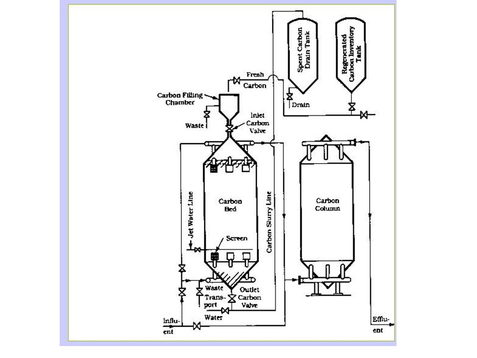
Carbon Regeneration Since activated carbon is relatively expensive, adsorption would not be feasible unless the carbon can be regenerated after exhaustion. Spent carbon is usually regenerated at 500 oC under low oxygen conditions in the presence of steam. Activated carbon loss is about 5-15% for each regeneration. Adsorbed organics are volatilized and oxidized during the regeneration process. A regeneration scheme is shown below.

75
Design Details: Carbon size – Upflow expanded –12 x 40 mesh (sieve openings per in2)(headloss and clogging not an issue) Downflow packed bed – 8 x 30 mesh . Hydraulic loading rate – Downflow packed bed: gpm/ft2 Upflow fluidized bed : 10% expansion 6 gpm/ft2 for 12x40 mesh, 10 gpm/ft2 for 8x30 mesh. Configuration Q typically 2 – 4 MGD per contactor in either series or parallel mode. Must allow for downtime of exhausted columns.

76
Column size: Pressure :cylindrical with less than 12 ft dia. and no deeper than 60ft. Open gravity system: surface area less than ft2 for even flow distribution 30 min empty bed contact time (EBCT) is typical.
 is typical.")
77
Backwash: Downflow or upflow packed bed must be periodically backwashed to 10% - 50% expansion . Flow requirements are 6 –14 gpm/ft2 for 12x40 mesh and gpm/ft2 for 8x30 mesh. Sometimes air scour or surface wash is required. Misc. factors: bio-growth helps regenerate AC by oxidizing adsorbed organics however can increase headloss due to potential clogging.; grease and oil clog micro and macro pores; Chlorine can oxidize AC and destroy it’s structural integrity

78
Competitive adsorption: If more than one solute is competing for the same adsorption site the isotherm must be modified. For example, the multi-solute Langmuir isotherm would look like:

79
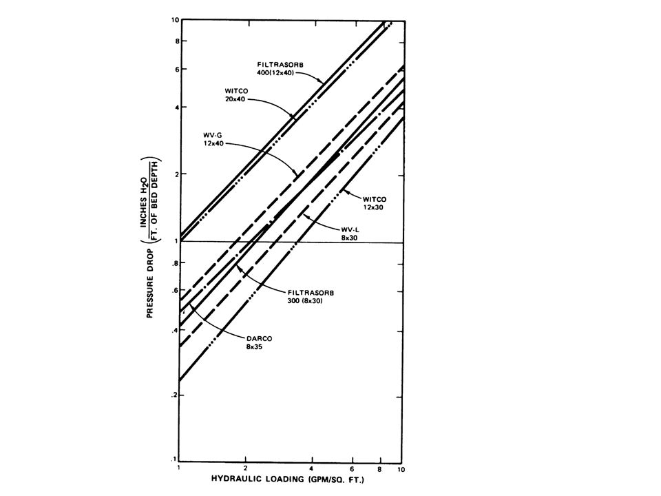
Headloss: Head loss in AC contactors is usually determined experimentally or from manufacturer’s specification. For example:

81
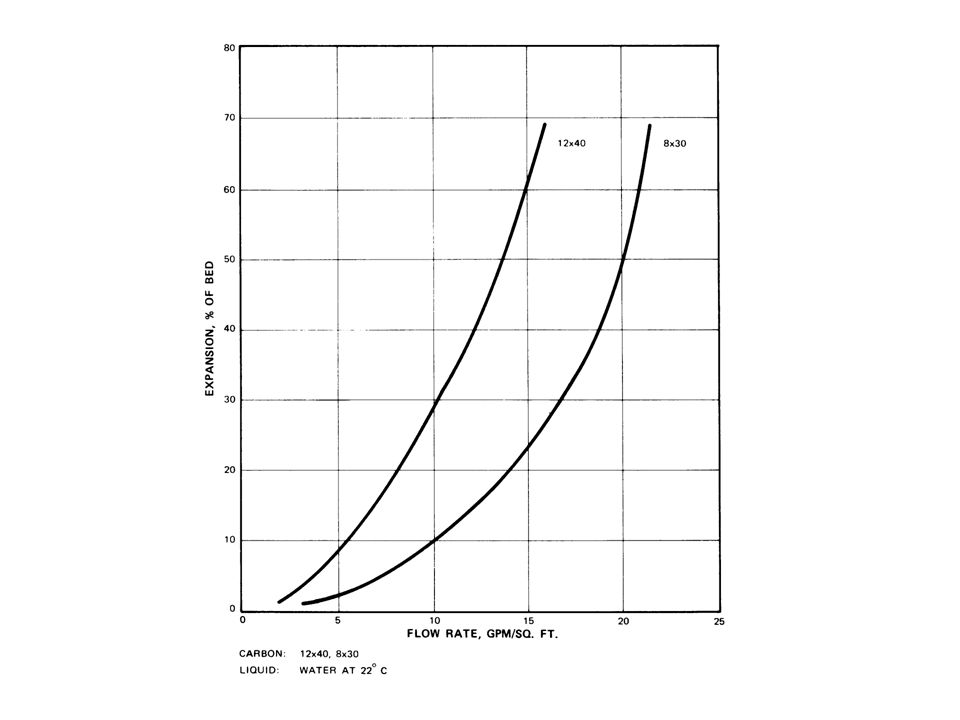
Backwashing is typically done to prevent excessive headloss during a run. Backwashing involves fluidizing the bed to release trapped suspended solids. For fluidization of the bed the following graph can be used.

83
Treatment trains incorporating AC contactors:
Carbon contactors in fixed bed mode will act as porous media filters, so suspended solids should be removed before a waste is applied to a contactor. In addition, AC will dechlorinate solutions (strong reaction between the carbon and Cl2), so AC should not be placed after a chlorination process unless dechlorination is desired. Some typical AC treatment schemes are shown below.
, so AC should not be placed after a chlorination process unless dechlorination is desired. Some typical AC treatment schemes are shown below.")
85
Applications in water treatment usually involve adding AC as a media to the filtration unit. In some cases a contactor is added just before the final chlorination step.

Similar presentations


 can be removed from the aqueous phase by stripping the VOC’s with an air flow.>")