Download presentation
Presentation is loading. Please wait.

1
Geometric Dimensioning and Tolerancing
Unit 1 – Introduction, Symbols, and Terms

3
Geometric Tolerancing Workbook
Everyone should have a workbook to follow along. It contains necessary reference information along with class exercises. Page numbers in yellow on the slides match pages in the workbook. The workbook for the class. The students should follow along with the workbook. There will be exercises at the end of each chapter for the student to complete. The answers are in the Leaders Guide which is available from Technical Consultants Inc. at the Longboat Key office.

4
History and Background
Eli Whitney, is the inventor of the cotton gin and a pioneer in the use of mass production methods. Around 1798, he won a contract to supply muskets to the United States government. The firearms manufacture were based on the concept of interchangeable parts. He made a presentation to congress by building 10 guns and assembling and disassembling them claiming the same exact parts and mechanisms. Eli Whitney

5
Tolerances All dimensions require a tolerance.
A tolerance should be as large as possible without interfering with the function of the part to minimize production costs. Consider how your part will be checked to see if it meets the tolerances.

6
Tolerance Notes

7
Limit Tolerancing

8
Limit Tolerancing

9
Limit Tolerancing Is the hole horizontal position measured from a true vertical plane or from the as built face? A .005” tolerance on the horizontal and vertical position of the hole means that the position could be off by as much as .007”. max allowed error for hole center +.005 .007 perfect location for hole center

10
Limit Tolerancing Limit tolerances don’t have an origin or any orientation or location relative to datums. The datums are usually implied. The drawings are subject to different interpretations. Plus/minus tolerancing works well for individual features of size (ex. diameter of a shaft), but does not control the relationship between individual features very well.
, but does not control the relationship between individual features very well.")
11
History of Dimensioning and Tolerancing Standards in the USA
Mil Std ’s Mil Std 8A Mil Std 8B Mil Std 8C-1963 ASA-Y USASI Y ANSI Y ANSI Y14.5M-1982 ASME Y14.5M-1994 ASME Y The first dimensioning and tolerancing standards in the USA were military standards in the 50’s. There were revisions A,B and C. The standards have undergone name changes in the past, American Standards Association (ASA). The current standard is the American Society of Mechanical Engineers (ASME Y ) The M in the title, which meant “metric compatible” was dropped because it was deemed no longer necessary. The standard can be used with both inch and metric values. It is a ASME standard with American National Standards Institute approval. Standards are always improved and work is taking place on the next revision. Additional information can be found at 1.3
. The current standard is the American Society of Mechanical Engineers (ASME Y ) The M in the title, which meant metric compatible was dropped because it was deemed no longer necessary. The standard can be used with both inch and metric values. It is a ASME standard with American National Standards Institute approval. Standards are always improved and work is taking place on the next revision. Additional information can be found at")
12
Introduction GDT is a language of symbols
We will see an overview of the symbols associated with: Dimensioning Symbols Geometric Characteristics Modifying Symbols

13
Dimensioning Symbols

14
Dimensioning Symbols Diameter Radius R

15
Dimensioning Symbols Spherical Diameter S Spherical Radius SR

16
Dimensioning Symbols Controlled Radius Tolerance CR Number of Places
A controlled radius has no ‘reversals’, but is a smooth curve within the tolerance zone.

17
Dimensioning Symbols Counterbore/Spotface Countersink

18
Dimensioning Symbols Depth/Deep Dimensions Not to Scale

19
Dimensioning Symbols Conical taper Slope

20
Dimensioning Symbols Square Reference Dimension

21
Dimensioning Symbols Dimension Origin Arc Length

22
Dimensioning Symbols All Around All Over

23
Dimensioning Symbols Chain Line
Used to identify a limited region to be treated differently from the rest of the part.

24
Introduction We will see an overview of the symbols associated with:
Dimensioning Symbols Geometric Characteristics Modifying Symbols

25
Geometric Characteristics
Explained in detail in Chapters 6 and 8.

26
Introduction We will see an overview of the symbols associated with:
Dimensioning Symbols Geometric Characteristics Modifying Symbols

27
Modifying Symbols

28
Modifying Symbols Maximum Material Condition MMC MMC
Refers to the size of the feature associated with the most material.

29
Modifying Symbols Least Material Condition LMC LMC
Refers to the size of the feature associated with the least material.

30
Modifying Symbols Continuous Feature Basic Dimension
Used to describe a theoretically exact size.

31
Modifying Symbols Between

32
Geometric Dimensioning and Tolerancing (GDT)
establish a reference coordinate system by defining datums provide basic dimensions (perfect dimensions) relative to the datums specify allowable tolerances
 relative to the datums. specify allowable tolerances.")
34
±1° 1.8 units are mm Common Symbols applied to a Drawing 25 10 18
This is a drawing with a lot of common symbols. The instructor should go over each of the symbols and show their application. Additional symbols will be introduced later in the course as they come up. Notice the old datum symbol from the 1982 standard. The reason for the change was to make the U.S, more compatible with ISO. Might see some older drawings like that. It is a negotiation process where all parties give and take. ISO meetings generally take place twice a year in various parts of the world. The American standards meets also take place twice during the year. They are open public meetings and anyone can attend. Contact ASME for more info. ±1° 1.8

36
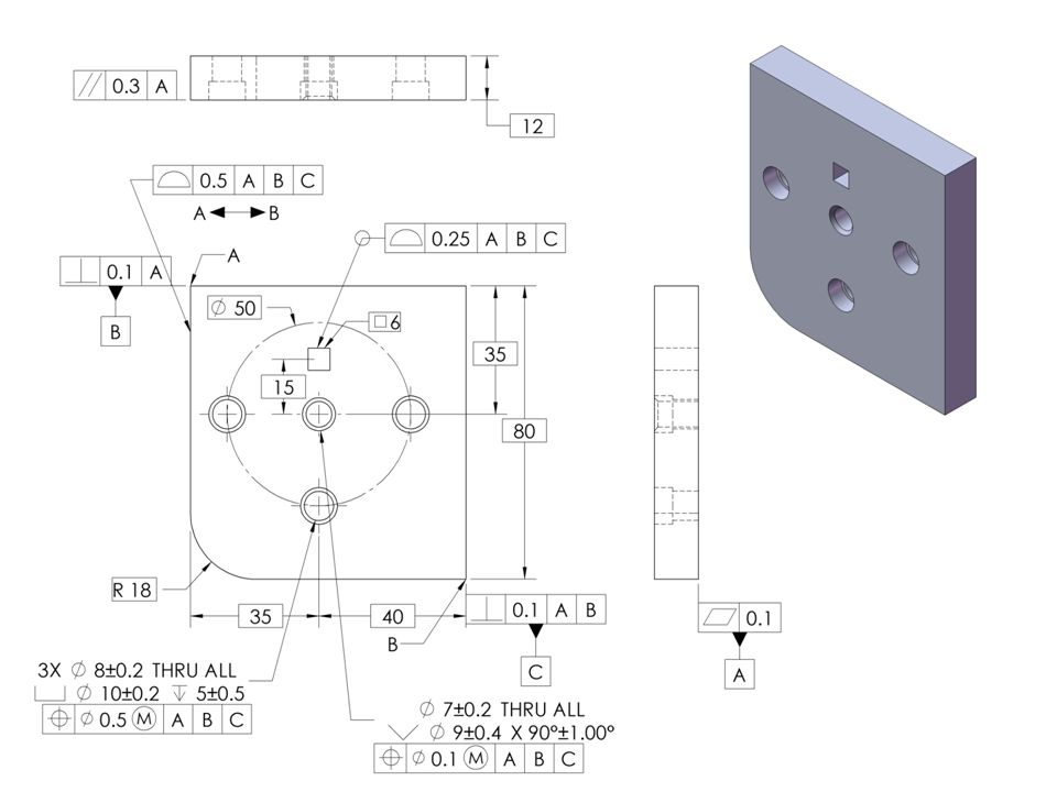
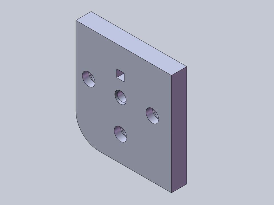
Indexer Assembly This is an indexer assembly. The drawing in the next slide iw the blue indexer plate in this assembly. Notice how the part fits in the assembly. The datums and the tolerancing scheme represent this functional assembly. 1.17

37
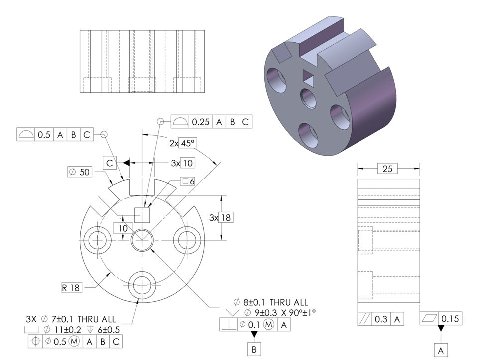
Indexer Plate This is a drawing with geometric tolerancing applied. The part shown has many features. Feature control frames are applied to the various features and give the instructions for that feature. Every feature control frame starts with the words, “This feature” flat, “This feature”, datum A. etc. The tolerance in every feature control frame is total, plus/minus is not allowed in the feature control frame. Notice that each feature has a feature control frame. It starts out with the left face defined as flat and referenced as a datum. Without the flatness spec it is not clear as to the flatness. The pilot pin is controlled perpendicular to datum A and referenced as datum B. Without the perp spec it is not clear as to the perp. The size dimension on the pilot does not control perp. The bottom flat surface is located to the pilot pin with a profile tolerance and referenced as datum C. The .900 basic dimension defines the distance of the bottom flat relative to the pilot pin. The 3 holes are located to the A,B, C datum reference frame by the basic bolt circle. General discussion should take place as to possible reasons the designer selected the datums and the various specifications based on the assemble shown on the preceding slide. General discussion should also take place as how the part is to be verified and manufactured considering the specifications. 1.17

38
Workshop Exercise 1.1 1.23 12 Student Exercise
Have the students work the problems in the GeoTol Pro and afterwards, click thru having the students help with the answers. We usually let them have open book so they become familiar with the book and can find information. 1.23

Similar presentations


>")


 with a mechanical focus.Objective: Given the Applying GD&T StAIR.>")


