Download presentation
Presentation is loading. Please wait.

1
Industrial Engineering Department King Saud University
IE433 CAD/CAM Computer Aided Design and Computer Aided Manufacturing Part-10 CNC Milling Programming Industrial Engineering Department King Saud University

2
Basic programming commands. Compensating an offset. Fixed cycles.
To maximize the power of modern CNC milling machines, a programmer has to master the following five categories of programming command codes and techniques: Basic programming commands. Compensating an offset. Fixed cycles. Macro and subroutine programs. Advanced programming features.

3
Basic programming commands.
• Motion commands (G00, G01, G02, G03) • Plane selection (G17, G18, G19) • Positioning system selection (G90, 091) • Unit selection (G70 or G20, G71 or G21) • Work coordinate setting (G92) • Reference point return (G28, G29, G30) • Tool selection and change (Txx M06) • Feed selection and input (Fxxx.xx, G94, 095) Spindle speed selection and control (Sxxxx, M03, M04, M05) • Miscellaneous functions (M00, M01, M02, M07, M08, M09, M30)
 • Plane selection (G17, G18, G19) • Positioning system selection (G90, 091) • Unit selection (G70 or G20, G71 or G21) • Work coordinate setting (G92) • Reference point return (G28, G29, G30) • Tool selection and change (Txx M06) • Feed selection and input (Fxxx.xx, G94, 095) Spindle speed selection and control (Sxxxx, M03, M04, M05) • Miscellaneous functions (M00, M01, M02, M07, M08, M09, M30)")
4
2. Compensation and offset
2. Compensation and offset. The use of compensation and offset functions in defining work coordinate systems, performing tool diameter compensations, and accommodating tool length differences often results in reduced programming effort. The main compensation and offset functions are • Work coordinate compensation (G54-G59) • Tool diameter (radius) compensation (G40, G41, G42) • Tool length offset (G43, G44, G49) 3. Fixed cycles. The purpose of a fixed cycle is to execute a series of repetitive machining operations with a single block command. Fixed cycles may be classified into the following three categories: • Standard fixed cycles (G80-G89) • Special fixed cycles • User-defined fixed cycles
 • Tool diameter (radius) compensation (G40, G41, G42) • Tool length offset (G43, G44, G49) 3. Fixed cycles. The purpose of a fixed cycle is to execute a series of repetitive machining operations with a single block command. Fixed cycles may be classified into the following three categories: • Standard fixed cycles (G80-G89) • Special fixed cycles. • User-defined fixed cycles.")
5
4. Macro and subroutine programming
4. Macro and subroutine programming. Most modem CNC controls furnish the power of computer programming to define variables, perform arithmetic operations, execute logical decisions, and so on. These features allow easy implementation of repetitive machining patterns and complex workpiece shapes that can be defined mathematically. Advanced programming features. These commands are dependent on user control. They are used to simplify programming effort and reduce programming time and program size. Typical features include scaling, rotation, and mirror image.

6
CNC Milling G-Codes G-codes are preparatory functions that involve actual tool moves (for example, control of the machine). These include rapid moves, feed moves, radial feed moves, dwells, and roughing and profiling cycles. Most G-codes described here are modal, meaning that they remain active until canceled by another G-code. The following codes are described in more detail in the following sections.
. These include rapid moves, feed moves, radial feed moves, dwells, and roughing and profiling cycles. Most G-codes described here are modal, meaning that they remain active until canceled by another G-code. The following codes are described in more detail in the following sections.")
7
CNC Milling G-Codes G00 Positioning in rapid Modal
G01 Linear interpolation Modal G02 Circular interpolation (CW) Modal G03 Circular interpolation (CCW) Modal G04 Dwell G17 XY plane Modal G18 XZ plane Modal G19 YZ plane Modal G20/G70 Inch units Modal
 Modal. G03 Circular interpolation (CCW) Modal. G04 Dwell. G17 XY plane Modal. G18 XZ plane Modal. G19 YZ plane Modal. G20/G70 Inch units Modal.")
8
CNC Milling G-Codes G21/G71 Metric units Modal
G28 Automatic return to reference point G29 Automatic return from reference point G40 Cutter compensation cancel Modal G41 Cutter compensation left Modal G42 Cutter compensation right Modal G43 Tool length compensation (plus) Modal G44 Tool length compensation (minus) Modal G49 Tool length compensation cancel Modal G54-G59 Workpiece coordinate settings Modal
 Modal. G44 Tool length compensation (minus) Modal. G49 Tool length compensation cancel Modal. G54-G59 Workpiece coordinate settings Modal.")
9
CNC Milling G-Codes G73 High-speed peck drilling Modal
G80 Cancel canned cycles Modal G81 Drilling cycle Modal G82 Counter boring cycle Modal G83 Deep hole drilling cycle Modal G90 Absolute positioning Modal G91 Incremental positioning Modal G92 Reposition origin point G98 Set initial plane default G99 Return to retract (rapid) plane
 plane.")
10
CNC Milling M-CODES M-codes are miscellaneous functions that include actions necessary for machining but not those that are actual tool movements. That is, they are auxiliary functions, such as spindle on and off, tool changes, coolant on and off, program stops, and similar related functions. The following codes are described in more detail in the following sections. M00 Program stop M01 Optional program stop M02 Program end M03 Spindle on clockwise M04 Spindle on counterclockwise

11
CNC Milling M-CODES M05 Spindle stop M06 Tool change M08 Coolant on
M09 Coolant off M10 Clamps on M11 Clamps off M30 Program end, reset to start M98 Call subroutine command M99 Return from subroutine command Block Skip Option to skip blocks that begin with ‘/’ Comments Comments may be included in blocks with round brackets ‘(’ ‘)’
’")
12
Tool Motion Command - G00 Positioning in Rapid
Format: N_ G00 X_ Y_ Z_ The G00 command is a rapid tool move. A rapid tool move is used to move the tool linearly from position to position without cutting any material. This command is not to be used for cutting any material, as to do so would seriously damage the tool and ruin the workpiece. It is a modal command, remaining in effect until canceled by another G-Code command

13
The G00 command is used to move the tool quickly from one point to another without cutting, thus allowing for quick tool positioning.

14
The G00 rapid move should have two distinct movements to ensure that vertical moves are always separate from horizontal moves. In a typical rapid move toward the part, the tool first rapids in the flat, horizontal XY plane. Then, it feeds down in the Z axis. When rapiding out of a part, the G00 command always goes up in the Z axis first, then laterally in the XY plane.

15
As this diagram shows, if the basic rules are not followed, an accident can result. Improper use of G00 often occurs because clamps are not taken into consideration. Following the basic rules will reduce any chance of error.

16
EXAMPLE: N25 G00 X2.5 Y (Rapid to X2.5,Y4.75) N30 Z (Rapid down to Z0.1) Depending on where the tool is located, there are two basic rules to follow for safety’s sake: If the Z value represents a cutting move in the negative direction, the X and Y axes should be executed first. If the Z value represents a move in the positive direction, the X and Y axes should be executed last.

17
Tool Start Position: X0,Y0,Z1
Sample Program : Workpiece Size: X6,Y4,Z1 Tool: Tool #2, 1/4" Slot Drill Tool Start Position: X0,Y0,Z1 % (Program start flag) : (Program number 1001) N5 G90 G20 (Absolute and inch programming) N10 M06 T2 (Tool change, Tool #2) N15 M03 S (Spindle on CW, at 1200 rpm) N20 G00 X1 Y1 (Rapid over to X1,Y1) N25 Z0.1 (Rapid down to Z0.1) N30 G01 Z-0.25 F5 (Feed move down to a depth of 0.25 in.) N35 Y3 (Feed move to Y3) N40 X5 (Feed to X5) N45 X1 Y1 Z (Feed to X1,Y1,Z–0.125) N50 G00 Z1 (Rapid up to Z1) N55 X0 Y0 (Rapid over to X0,Y0) N60 M05 (Spindle off) N65 M30 (End of program)
 :1001 (Program number 1001) N5 G90 G20 (Absolute and inch programming) N10 M06 T2 (Tool change, Tool #2) N15 M03 S1200 (Spindle on CW, at 1200 rpm) N20 G00 X1 Y1 (Rapid over to X1,Y1) N25 Z0.1 (Rapid down to Z0.1) N30 G01 Z-0.25 F5 (Feed move down to a depth of 0.25 in.) N35 Y3 (Feed move to Y3) N40 X5 (Feed to X5) N45 X1 Y1 Z (Feed to X1,Y1,Z–0.125) N50 G00 Z1 (Rapid up to Z1) N55 X0 Y0 (Rapid over to X0,Y0) N60 M05 (Spindle off) N65 M30 (End of program)")
18
G01 Linear Interpolation Format: N_ G01 X_ Y_ Z_ F_
The G01 command is specifically for the linear removal of material from a workpiece, in any combination of the X, Y, or Z axes. The machine tool follows a linear trajectory. The G01 is modal and requires a user variable feedrate (designated by the letter F followed by a number).
.")
19
Linear Interpolation, or straight-line feed moves, on the flat XY plane (no Z values are specified).
G01 command, using multi-axis feed moves. All diagonal feed moves are a result of a G01 command, where two or more axes are used at once.

20
Sample Program (G01): Workpiece Size: X4, Y3, Z1 Tool: Tool #3, 3/8" Slot Drill Tool Start Position: X0, Y0, Z1 % (Program start flag) : (Program #1002) N5 G90 G20 (Block #5, absolute in inches) N10 M06 T3 (Tool change to Tool #3) N15 M03 S (Spindle on CW at 1250 rpm) N20 G00 X1.0 Y1.0 (Rapid over to X1,Y1) N25 Z (Rapid down to Z0.1) N30 G01 Z F5 (Feed down to Z–0.125 at 5 ipm) N35 X3 Y2 F10 (Feed diagonally to X3,Y2 at 10 ipm) N40 G00 Z (Rapid up to Z1) N45 X0.0 Y (Rapid over to X0,Y0) N50 M05 (Spindle off) N55 M30 (Program end)
 :1002 (Program #1002) N5 G90 G20 (Block #5, absolute in inches) N10 M06 T3 (Tool change to Tool #3) N15 M03 S1250 (Spindle on CW at 1250 rpm) N20 G00 X1.0 Y1.0 (Rapid over to X1,Y1) N25 Z0.1 (Rapid down to Z0.1) N30 G01 Z F5 (Feed down to Z–0.125 at 5 ipm) N35 X3 Y2 F10 (Feed diagonally to X3,Y2 at 10 ipm) N40 G00 Z1.0 (Rapid up to Z1) N45 X0.0 Y0.0 (Rapid over to X0,Y0) N50 M05 (Spindle off) N55 M30 (Program end)")
21
G02 Circular Interpolation (clockwise)
Format: N_ G02 X_ Y_ Z_ I_ J_ K_ F_ or N_ G02 X_ Y_ Z_ R_ F_ Circular Interpolation is more commonly known as radial (or arc) feed moves. The G02 command is specifically used for all clockwise radial feed moves, whether they are quadratic arcs, partial arcs, or complete circles, as long as they lie in any one plane. The G02 command is modal and is subject to a user-definable feed rate.
 feed moves. The G02 command is specifically used for all clockwise radial feed moves, whether they are quadratic arcs, partial arcs, or complete circles, as long as they lie in any one plane. The G02 command is modal and is subject to a user-definable feed rate.")
22
G02 Circular Interpolation (cont'd.)
The G02 command requires an endpoint and a radius in order to cut the arc. The start point of this arc is (X1,Y4) and the endpoint is (X4,Y1). To find the radius, simply measure the incremental distance from the start point to the center point. This radius is written in terms of the X and Y distances. To avoid confusion, these values are assigned variables, called I and J, respectively.
 and the endpoint is (X4,Y1). To find the radius, simply measure the incremental distance from the start point to the center point. This radius is written in terms of the X and Y distances. To avoid confusion, these values are assigned variables, called I and J, respectively.")
23
EXAMPLE: G02 X2 Y1 I0 J-1 The G02 command requires an endpoint and a radius in order to cut the arc. The start point of this arc is (X1, Y2) and the end-point is (X2, Y1). To find the radius, simply measure the relative, (or incremental), distance from the start point to the center point. This radius is written in terms of the X and Y distances. To avoid confusion, these values are assigned variables called I and J, respectively.
 and the end-point is (X2, Y1). To find the radius, simply measure the relative, (or incremental), distance from the start point to the center point. This radius is written in terms of the X and Y distances. To avoid confusion, these values are assigned variables called I and J, respectively.")
24
EXAMPLE: G02 X2 Y1 R1 You can also specify G02 by entering the X and Y endpoints and then R for the radius. Note: The use of an R value for the radius of an arc is limited to a maximum movement of 90°. An easy way to determine the radius values (the I and J values) is by making a small chart: Center point X1 Y1 Start point X1 Y2 Radius I0 J-1 Finding the I and J values is easier than it first seems. Follow these steps: 1. Write the X and Y coordinates of the arc’s center point. 2. Below these coordinates, write the X and Y coordinates of the arc’s start point. 3. Draw a line below this to separate the two areas to perform the subtraction. Result: G02 X2 Y1 I0 J-1 F5 4. To find the I value, calculate the difference between the arc’s start point and center point in the X direction. In this case, both X values are 1. Hence there is no difference between them, so the I value is 0. To find the J value, calculate the difference between the arc’s start point and center point in the Y direction. In this case, the difference between Y2 and Y1 is down 1 inch, so the J value is –1.
 is by making a small chart: Center point X1 Y1. Start point X1 Y2. Radius I0 J-1. Finding the I and J values is easier than it first seems. Follow these steps: 1. Write the X and Y coordinates of the arc’s center point. 2. Below these coordinates, write the X and Y coordinates of the arc’s start point. 3. Draw a line below this to separate the two areas to perform the subtraction. Result: G02 X2 Y1 I0 J-1 F5. 4. To find the I value, calculate the difference between the arc’s start point and center point in the X direction. In this case, both X values are 1. Hence there is no difference between them, so the I value is 0. To find the J value, calculate the difference between the arc’s start point and center point in the Y direction. In this case, the difference between Y2 and Y1 is down 1 inch, so the J value is –1.")
25
N55 G00 Z0.1 Sample Program (G02): Workpiece Size: X4, Y3, Z1
Tool: Tool #2, 1/4" Slot Drill Tool Start Position: X0, Y0, Z1 % :1003 N5 G90 G20 N10 M06 T2 N15 M03 S1200 N20 G00 X1 Y1 N25 Z0.1 N30 G01 Z-0.1 F5 N35 G02 X2 Y2 I1 J0 F20 (Arc feed CW, radius I1,J0 at 20 ipm) N40 G01 X3.5 N45 G02 X3 Y0.5 R2 (Arc feed CW, radius 2) N50 X1 Y1 R2 (Arc feed CW, radius 2) N55 G00 Z0.1 N60 X2 Y1.5 N65 G01 Z-0.25 N70 G02 X2 Y1.5 I0.25 J (Full circle arc feed move CW) N75 G00 Z1 N80 X0 Y0 N85 M05 N90 M30
 N40 G01 X3.5. N45 G02 X3 Y0.5 R2 (Arc feed CW, radius 2) N50 X1 Y1 R2 (Arc feed CW, radius 2) N55 G00 Z0.1. N60 X2 Y1.5. N65 G01 Z N70 G02 X2 Y1.5 I0.25 J-0.25 (Full circle arc feed move CW) N75 G00 Z1. N80 X0 Y0. N85 M05. N90 M30.")
26
G03 CIRCULAR INTERPOLATION (CCW)
Format: N_ G03 X_ Y_ Z_ I_ J_ K_ F_ (I, J, K specify the radius) The G03 command is used for all counterclockwise radial feed moves, whether they are quadratic arcs, partial arcs, or complete circles, as long as they lie in any one plane. The G03 command is modal and is subject to a user-definable feed rate
 The G03 command is used for all counterclockwise radial feed moves, whether they are quadratic arcs, partial arcs, or complete circles, as long as they lie in any one plane. The G03 command is modal and is subject to a user-definable feed rate.")
27
EXAMPLE: G03 X1 Y1 I0 J-1 The G03 command requires an endpoint and a radius in order to cut the arc. (See Fig. 5.7.) The start point of this arc is (X2, Y2) and the end-point is (X1, Y1). To find the radius, simply measure the incremental distance from the start point to the center point of the arc. This radius is written in terms of the X and Y distances. To avoid confusion, these values are assigned variables called I and J, respectively.
 The start point of this arc is (X2, Y2) and the end-point is (X1, Y1). To find the radius, simply measure the incremental distance from the start point to the center point of the arc. This radius is written in terms of the X and Y distances. To avoid confusion, these values are assigned variables called I and J, respectively.")
28
EXAMPLE: G03 X1 Y1 R1 You can also specify G03 by entering the X and Y endpoints and then R for the radius. Note: The use of an R value for the radius of an arc is limited to a maximum movement of 90°. An easy way to determine the radius values (the I and J values) is to make a small chart as follows. Center point X2 Y1 Start point X2 Y2 Radius I0 J-1 Finding the I and J values is easier than it first seems. Follow these steps: 1. Write the X and Y coordinates of the arc’s center point. 2. Below these coordinates, write the X and Y coordinates of the arc’s start point. 3. Draw a line below this to separate the two areas to perform the subtraction. 4. To find the I value, calculate the difference between the arc’s start point and center point in the X direction. In this case, both X values are 2. Hence there is no difference between them, so the I value is 0. To find the J value, calculate the difference between the arc’s start point and center point in the Y direction. In this case, the difference between Y2 and Y1 is down 1 inch, so the J value is –1. Result: G03 X1 Y1 I0 J-1
 is to make a small chart as follows. Center point X2 Y1. Start point X2 Y2. Radius I0 J-1. Finding the I and J values is easier than it first seems. Follow these steps: 1. Write the X and Y coordinates of the arc’s center point. 2. Below these coordinates, write the X and Y coordinates of the arc’s start point. 3. Draw a line below this to separate the two areas to perform the subtraction. 4. To find the I value, calculate the difference between the arc’s start point and center point in the X direction. In this case, both X values are 2. Hence there is no difference between them, so the I value is 0. To find the J value, calculate the difference between the arc’s start point and center point in the Y direction. In this case, the difference between Y2 and Y1 is down 1 inch, so the J value is –1. Result: G03 X1 Y1 I0 J-1.")
29
G03 Circular Interpolation (cont'd)
The G03 command requires an endpoint and a radius in order to cut the arc. The start point of this arc is (X4,Y1) and the endpoint is(X1,Y4). To find the radius, simply measure the incremental distance from the start point to the center point. This radius is written in terms of the X and Y distances. To avoid confusion, these values are assigned variables I and J, respectively.
 and the endpoint is(X1,Y4). To find the radius, simply measure the incremental distance from the start point to the center point. This radius is written in terms of the X and Y distances. To avoid confusion, these values are assigned variables I and J, respectively.")
30
NOTE: Programming the G02 and G03 commands with an R value is reserved only for arcs less than or equal to 90 degrees. The more common method involves the use of trigonometry to solve for the I, J, or K values.

31
N105 M30 Sample Program (G03). Workpiece Size: X4, Y4, Z0.25
Tool: Tool #2, 1/4" Slot Drill Tool Start Position: X0, Y0, Z1 % :1004 N5 G90 G20 N10 M06 T2 N15 M03 S1200 N20 G00 X2 Y0.5 N25 Z0.125 N30 G01 Z F5 N35 X3 F15 N40 G03 X3.5 Y1 R (G03 arc using R value) N45 G01 Y3 N50 G03 X3 Y3.5 I-0.5 J0 (G03 arc using I and J) N55 G01 X2 N60 G03 X2 Y1.5 I0 J-1 (180° arc using I and J) N65 G01 Y0.5 N70 G00 Z0.1 N75 X1.5 Y2.5 N80 G01 Z-0.25 F5 N85 G03 X1.5 Y2.5 I0.5 J0 (Full circle using I and J) N90 G00 Z1 N95 X0 Y0 N100 M05 N105 M30
 N45 G01 Y3. N50 G03 X3 Y3.5 I-0.5 J0 (G03 arc using I and J) N55 G01 X2. N60 G03 X2 Y1.5 I0 J-1 (180° arc using I and J) N65 G01 Y0.5. N70 G00 Z0.1. N75 X1.5 Y2.5. N80 G01 Z-0.25 F5. N85 G03 X1.5 Y2.5 I0.5 J0 (Full circle using I and J) N90 G00 Z1. N95 X0 Y0. N100 M05. N105 M30.")
32
Command Format with IJK Method
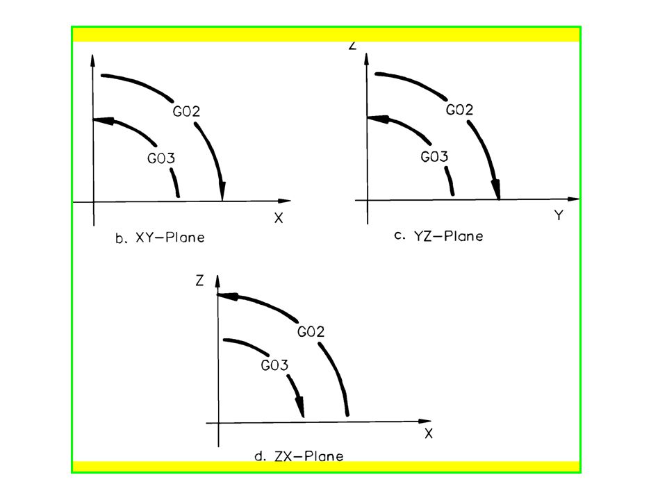
(GI7) G02 (or G03) Xx Yy li Ji Ff on XY-plane (G18) G02 (or G03) Xx Zz li Kk Ff on ZX-plane (G19) G02 (or G03) Yy Zz Jj Kk Ff on YZ-plane Command Format with R Method (GI7) G02 (or G03) Xx Yy Rr Ff on XY-plane (G18) G02 (or G03) Xx Zz Rr Ff on ZX-plane (G19) G02 (or G03) Yy Zz Rr Ff on YZ-plane
 G02 (or G03) Xx Yy li Ji Ff on XY-plane. (G18) G02 (or G03) Xx Zz li Kk Ff on ZX-plane. (G19) G02 (or G03) Yy Zz Jj Kk Ff on YZ-plane. Command Format with R Method. (GI7) G02 (or G03) Xx Yy Rr Ff on XY-plane. (G18) G02 (or G03) Xx Zz Rr Ff on ZX-plane. (G19) G02 (or G03) Yy Zz Rr Ff on YZ-plane.")
33
G04 DWELL Format: N_ G04 P_ The G04 command is a nonmodal dwell command that halts all axis movement for a specified time while the spindle continues revolving at the specified rpm. A dwell is used largely in drilling operations and after plunge moves, which allows for the clearance of chips .

34
Sample Program (G04): Workpiece Size: X3.5, Y2, Z0.5
Tool: Tool #1, 1/8" Slot Mill Tool Start Position: X0, Y0, Z1 % (Program start flag) : (Program #1005) N5 G90 G20 (Absolute programming in inch mode) N10 M06 T1 (Tool change to Tool #1) N15 M03 S (Spindle on CW at 1300 rpm) N20 G00 X3 Y1 Z0.1 (Rapid to X3,Y1,Z0.1) N25 G01 Z F5.0 (Feed down to Z–0.125 at 5 ipm) N30 G04 P2 (Dwell for 2 seconds) N35 G00 X2 Z0.1 (Rapid up to 0.1) N33 X2 (Rapid to X2) N40 G01 Z F5.0 (Feed down to Z–0.125) N45 G04 P1 (Dwell for 1 second) N50 G00 Z1.0 (Rapid out to Z1) N55 X0. Y0. (Rapid to X0, Y0) N60 M05 (Spindle off) N65 M30 (Program end)
 :1005 (Program #1005) N5 G90 G20 (Absolute programming in inch mode) N10 M06 T1 (Tool change to Tool #1) N15 M03 S1300 (Spindle on CW at 1300 rpm) N20 G00 X3 Y1 Z0.1 (Rapid to X3,Y1,Z0.1) N25 G01 Z F5.0 (Feed down to Z–0.125 at 5 ipm) N30 G04 P2 (Dwell for 2 seconds) N35 G00 X2 Z0.1 (Rapid up to 0.1) N33 X2 (Rapid to X2) N40 G01 Z F5.0 (Feed down to Z–0.125) N45 G04 P1 (Dwell for 1 second) N50 G00 Z1.0 (Rapid out to Z1) N55 X0. Y0. (Rapid to X0, Y0) N60 M05 (Spindle off) N65 M30 (Program end)")
35
G17 XY Plane Format: N_ G17

36
G18 XY Plane Format: N_ G18

37
G19 XY Plane Format: N_ G19

38
G17 = XY plane G18 = XZ plane G19 = YZ plane

40
G20 or G70 Inch Units Format: N_ G20 or G70
The G20 or G70 command defaults the system to inch units. When a program is being run and the G20 command is encountered, all coordinates are stated as inch units. This command is usually found at the beginning of a program. However, on some controllers it can be used to switch from metric units in the middle of a program.

41
G21 or G71 Metric, or SI, Units Format: N_ G21 or G71
The G21 or G71 command defaults the system to metric units. When a program is being run and the G21 command is encountered, all coordinates are stated in as millimeter units. This command is usually found at the beginning of a program. However, it can be used to switch between metric and inch units in the middle of a program.

42
G28 Automatic Return to Reference Format: N_ G28 X_ Y_ Z_
The G28 command is primarily used before automatic tool changing. It allows the existing tool to be positioned to the predefined reference point automatically via an intermediate position. This ensures that when the tool changer is engaged, it is properly aligned with the spindle head. NOTE: When this command is being used, it is advisable for safety reasons to cancel any tool offset or cutter compensation.

43
G29 Automatic Return from Reference Format: N_ G29 X_ Y_ Z_
The G29 command can be used immediately after an automatic tool change. It allows the new tool to be returned from the predefined reference point to the specified point via an intermediate point specified by the previous G28 command. NOTE: When this command is being used, it is advisable for safety reasons to cancel any tool offset or cutter compensation.

44
G40 Cutter Compensation Cancel Format: N_ G40
Usually, CNC programs are written so that the tool center follows the toolpath. Cutter compensation is used whenever tool centerline programming is difficult. It is also used to compensate for significant tool wear or tool substitution. The G40 command cancels any cutter compensation that was applied to the tool during a program and acts as a safeguard to cancel any cutter compensation applied to a previous program or G-codes. NOTE: Cutter compensation is modal, so it must be canceled when it is no longer needed. This is the sole function of the G40 command

45
G41 Cutter Compensation Left Format: N_ G41 D_
The G41 command compensates the cutter a specified distance to the left-hand side of the programmed tool path. It is used to compensate for excessive tool wear or substitute a tool to profile a part. The G41 command is modal, so it compensates each successive tool move the same specified distance until it is overridden by a G40 command or receives a different offset.

46
G41 Cutter Compensation Left Format: N_ G41 D_

47
Sample program (G41): Workpiece Size: X5, Y4, Z1 Tool: Tool #1, 1/4" Slot Drill Tool #4, 1/2" End Mill Register: D11 is 0.25" Tool Start Position:X0, Y0, Z1 % :1012 N5 G90 G20 G40 G17 G80 N10 T01 M06 N15 M03 S2000 N20 G00 X0.5 Y0.5 N25 Z0.1 N30 G01 Z-0.25 F5 N35 X2 F15 N40 X2.5 Y1 N45 Y2 N50 G03 X2 Y2.5 R0.5 N55 G01 X0.5 N60 Y0.5 N65 G00 Z1 N70 X0 Y0 N75 M06 T04 N80 M03 S1000 N85 G00 X0.75 Y1 N90 Z0.125 N95 G01 Z-0.25 F5 N100 G41 X0.5 Y0.5 D11 F20 N105 X2 N110 X2.5 Y1 N115 Y2 N120 G03 X2 Y2.5 R0.5 N125 G01 X0.5 N130 Y0.5 N135 G40 X0.75 Y0.75 N140 G00 Z1 N145 X0 Y0 N150 M05 N155 M30

48
G42 CUTTER COMPENSATION RIGHT
Format: N_ G42 D_ The G42 command compensates the cutter a specified distance to the right-hand side of the programmed tool path. It is used to compensate for excessive tool wear or substitute a tool to profile a part. The G42 command is modal, so it compensates each successive tool move the same specified distance until it is overridden by a G40 command or receives a different offset.

49
G42 CUTTER COMPENSATION RIGHT
Format: N_ G42 D_

50
Sample Program (G42): Workpiece Size: X4, Y4, Z1 Tool: Tool #1, 1/4" Slot Drill Tool #4, 1/2" End Mill Register: D11 is 0.25" Tool Start Position: X0, Y0, Z1 % :1013 N5 G90 G20 G40 G17 G80 N10 T01 M06 N15 M03 S2000 N20 G00 X0.5 Y0.5 N25 Z0.1 N30 G01 Z-0.25 F5 N35 X2 F15 N40 X2.5 Y1 N45 Y2 N50 G03 X2 Y2.5 R0.5 N55 G01 X0.5 N60 Y0.5 N65 G00 Z1 N70 X0 Y0 N75 T04 M06 N80 M03 S1000 N85 G00 X-0.5 N90 Z-0.5 N95 G01 G42 X0.5 Y0.5 Z-0.5 D11 F15 N100 X2 N105 X2.5 Y1 N110 Y2 N115 G03 X2 Y2.5 R0.5 N120 G01 X0.5 N125 Y0 N130 G01 G40 Z0.25 N135 G00 Z1 N140 X0 Y0 N145 M05 N150 M30

51
G43 Tool Length Compensation (Plus) Format: N_ G43 H_
The G43 command compensates for tool length in a positive direction. It is important to realize that different tools will have varying lengths, and when tools are changed in a program, any variation in tool length will throw the origin out of zero. To prevent this, the difference in tool length should be compensated for.

52
G43 Tool Length Compensation (Plus) Format: N_ G43 H_
 Format: N_ G43 H_")
53
G44 Tool Length Compensation (Minus) Format: N_ G44 H_
The G44 command compensates for tool length in a minus direction. It is important to realize that different tools will have varying lengths, and when tools are changed in a program, any variation in tool length will throw the origin out of zero. To prevent this, the difference in tool length should be compensated for.

54
G44 Tool Length Compensation (Minus) Format: N_ G44 H_
 Format: N_ G44 H_")
55
G49 Tool Length Compensation Cancel Format: N_ G49
The G49 command cancels all previous cutter length offset commands. Because the G43 and G44 commands are modal, they will remain active until canceled by the G49 command. It is important to keep this in mind; forgetting that a tool has been offset can cause the cutter to crash into the workpiece.

56
G54–G59 Workpiece Coordinate System Format: N_ G54 through G59
The G54 – G59 commands are used to reposition the origin per a user- defined working coordinate system. In CNCez six register sets in the controller hold the values for the working coordinate systems. The G54 – G59 commands are very useful when multiple workpiece fixtures are used. On real CNC controllers these values are held in parameter fields which are normally set in the parameters entry screen of the controller.

57
G73 High-Speed Peck Drilling Cycle Format: N_ G73 X_ Y_ Z_ R_ Q_ F_
During a G73 high-speed peck drilling cycle, the tool feeds in to the peck distance or depth of cut, then retracts a small pre-determined distance, which is the chip-breaking process, and then feeds to the next peck, which takes the tool deeper. This process is repeated until the final Z depth is reached. Because the tool doesn't retract fully from the hole, as in the G83 cycle, it minimizes cycle time and improves total part machining time.

58
G80 Cancel Canned Cycles Format: N_ G80
The G80 command cancels all previous canned cycle commands. Because the canned cycles are modal (refer to the canned cycles on the following pages), they will remain active until canceled by the G80 command. Canned cycles include tapping, boring, spot facing, and drilling. Note: On most controllers the G00 command will also cancel any canned cycles.
, they will remain active until canceled by the G80 command. Canned cycles include tapping, boring, spot facing, and drilling. Note: On most controllers the G00 command will also cancel any canned cycles.")
59
G81 Drilling Cycle Format: N_ G81 X_ Y_ Z_ R_ F_
The G81 command invokes a drill cycle at specified locations. This cycle can be used for bolt holes, drilled patterns, and mold sprues, among other tasks. This command is modal and so remains active until overridden by another move command or canceled by the G80 command. Invoking the G81 command requires invoking the Z initial plane, Z depth and Z retract plane parameters.

60
G82 Spot Drilling or Counter Boring Cycle Format: N_ G82 X_ Y_ Z_ R_ P_ F_
This cycle follows the same operating procedures as the G81 drilling cycle, with the addition of a dwell. The dwell is a pause during which the Z axis stops moving but the spindle continues rotating. This pause allows for chip clearing and a finer finish on the hole. The dwell time is measured in seconds. The dwell is specified by the P letter address, followed by the dwell time in seconds. The same Z levels apply to the G82 cycle as to the G81 cycle: Z initial plane, Z depth and Z retract.

61
G83 Deep Hole Drilling Cycle Format: N_ G83 X_ Y_ Z_ R_ Q_ F_
The G83 command involves individual peck moves in each drilling operation. When this command is invoked, the tool positions itself as in a standard G81 drill cycle. The peck is the only action that distinguishes the deep hole drilling cycle from the G81 cycle. When pecking, the tool feeds in the specified distance (peck distance or depth of cut), then rapids back out to the Z Retract plane. The next peck takes the tool deeper, and then it rapids out of the hole. This process is repeated until the final Z depth is reached. In the G83 cycle, Q is the incremental depth of cut.
, then rapids back out to the Z Retract plane. The next peck takes the tool deeper, and then it rapids out of the hole. This process is repeated until the final Z depth is reached. In the G83 cycle, Q is the incremental depth of cut.")
62
G90 Absolute Positioning Format: N_ G90
The G90 command defaults the system to accept all coordinates as absolute coordinates. These coordinates are measured from a fixed origin (X0, Y0, Z0) and expressed in terms of X, Y, and Z distances.
 and expressed in terms of X, Y, and Z distances.")
63
G91 Incremental Positioning Format: N_ G91
The G91 command defaults the system to accept all coordinates as incremental, or relative, coordinates.

64
G92 Reposition Origin Point Format: N_ G92 X_ Y_ Z_
The G92 command is used to reposition the origin point. The origin point is not a physical spot on the machine tool, but rather a reference point to which the coordinates relate. Generally, the origin point is located at a prominent point or object (for example, front top left corner of the part) so that it is easier to measure from.
 so that it is easier to measure from.")
65
G98 Set Initial Plane Rapid Default Format: N_ G98
The G98 command forces the tool to return to the Z initial plane a drilling operation. This forces the tool up and out of the workpiece. This setting is normally used when a workpiece has clamps or other obstacles that could interfere with tool movement. The G98 command is also the system default.

66
G99 Set Rapid to Retract Plane Format: N_ G99
The G99 command forces the tool to return to the retract plane after a drilling operation. This forces the tool up and out of the workpiece to the retract plane specified in the drilling cycle, overriding the system default. This command is usually used on drilling cycles within a pocket, or on workpieces that do not have surface obstacles. It is quicker than the G98 command because the tool moves only to the retract plane.

67
CNC Milling – M- Codes M-codes are miscellaneous functions that include actions necessary for machining but not those that are actual tool movements (for example, auxiliary functions). They include actions such as spindle on and off, tool changes, coolant on and off, program stops, and similar related functions.
. They include actions such as spindle on and off, tool changes, coolant on and off, program stops, and similar related functions.")
68
M-Codes M00 Program stop M01 Optional program stop M02 Program end
M03 Spindle on clockwise M04 Spindle on counterclockwise M05 Spindle stop M06 Tool change M08 Coolant on M09 Coolant off M10 Clamps on M11 Clamps off M30 Program end, reset to start M98 Call subroutine command M99 Return from subroutine command Block Skip Option to skip blocks that begin with ‘/’ Comments Comments may be included in blocks with round brackets ‘(’ ‘)’
’")
69
M01 Optional Program Stop
M00 - Program stop Format: N_ M00 The M00 command is a temporary program stop function. When it is executed, all functions are temporarily stopped and will not restart unless and until prompted by user input. This command can be used in lengthy programs to stop the program in order to clear chips, take measurements, or adjust clamps, coolant hoses, and so on. M01 Optional Program Stop Format: N_ M01 If the Optional Stop switch is set to ON, the program will stop when it encounters in an M01command. Both real CNC controllers and the CNCez simulators have this feature.

70
M02 PROGRAM END Format: N_ M02
The M02 command indicates an end of the main program cycle operation. Upon encountering the M02 command, the MCU switches off all machine operations (for example, spindle, coolant, all axes, and any auxiliaries), terminating the program. This command appears on the last line of the program. Sample Program (M02): Workpiece Size: X4, Y3, Z1 Tool: Tool #2, 1/4" Slot Drill Tool Start Position: X0, Y0, Z1 % :1003 N5 G90 G20 N10 M06 T2 N15 M03 S1200 N20 G00 X1 Y1 N25 Z0.1 N30 G01 Z-.125 F5 N35 X3 F15 N40 G00 Z1 N45 X0 Y0 N50 M05 N55 M02 (Program end)
, terminating the program. This command appears on the last line of the program. Sample Program (M02): Workpiece Size: X4, Y3, Z1. Tool: Tool #2, 1/4 Slot Drill. Tool Start Position: X0, Y0, Z1. % :1003. N5 G90 G20. N10 M06 T2. N15 M03 S1200. N20 G00 X1 Y1. N25 Z0.1. N30 G01 Z-.125 F5. N35 X3 F15. N40 G00 Z1. N45 X0 Y0. N50 M05. N55 M02 (Program end)")
71
M03 SPINDLE ON CLOCKWISE Format: N_ M03 S_
The M03 command switches the spindle on in a clockwise rotation. The spindle speed is designated by the S letter address, followed by the spindle speed in revolutions per minute

72
M04 SPINDLE ON COUNTERCLOCKWISE
Format: N_ M04 S_ The M04 command switches the spindle on in a counterclockwise rotation. The spindle speed is designated by the S letter address, followed by the spindle speed in revolutions per minute.

73
M05 SPINDLE STOP Format: N_ M05 The M05 command turns the spindle off. Although other M-codes turn off all functions (for example, M00 and M01), this command is dedicated to shutting the spindle off directly. The M05 command appears at the end of a program. M06 TOOL CHANGE Format: N_ M06 T_ The M06 command halts all program operations for a tool change. It is actually a two-fold command. First, it stops all machine operations—for example, the spindle is turned off and oriented for the tool change, and all axes motion stops—so that it is safe to change the tool. Second, it actually changes the tool
, this command is dedicated to shutting the spindle off directly. The M05 command appears at the end of a program. M06 TOOL CHANGE. Format: N_ M06 T_. The M06 command halts all program operations for a tool change. It is actually a two-fold command. First, it stops all machine operations—for example, the spindle is turned off and oriented for the tool change, and all axes motion stops—so that it is safe to change the tool. Second, it actually changes the tool.")
74
M06 TOOL CHANGE Format: N_ M06 T_

75
M07/M08 COOLANT ON Format: N_ M07 or N_ M08 The M07 and M08 commands switch on the coolant flow. M09 COOLANT OFF Format: N_ M09 The M09 command shuts off the coolant flow. The coolant should be shut off prior to tool changes or when you are rapiding the tool over long distances.

76
M08 Coolant On or M09 Coolant Off Format: N_ M08 or N_ M09

77
M10 CLAMPS ON Format: N_ M10 The M10 command turns on the automatic clamps to secure the workpiece. Automatic clamps can be pneumatic, hydraulic, or electromechanical. Not all CNC machines have automatic clamps, but the option exists and the actual code will vary by machine tool make and model.

78
M11 CLAMPS OFF Format: N_ M11 The M11 command releases the automatic clamps so that the work-piece may be removed and the next blank inserted. The automatic clamps may be pneumatic, hydraulic, or electromechanical, depending on the application.

79
Sample Program M11EX10: Workpiece Size: X4, Y3, Z1 Tool: Tool #12, 1" End Mill Tool Start Position: X0, Y0, Z1 % :1011 N5 G90 G20 N10 M06 T12 N15 M10 (Clamp workpiece) N20 M03 S1000 N25 G00 X-0.75 Y1 N30 Z-0.375 N35 G01 X0 F10 N40 G03 Y2 I0 J0.5 N45 G01 X2 Y3 N50 X4 Y2 N55 G03 Y1 I0 J-0.5 N60 G01 X2 Y0 N65 X0 Y1 N70 G00 Z1 N75 X0 Y0 N80 M05 N85 M11 (Unclamp workpiece) N90 M30
 N20 M03 S1000. N25 G00 X-0.75 Y1. N30 Z N35 G01 X0 F10. N40 G03 Y2 I0 J0.5. N45 G01 X2 Y3. N50 X4 Y2. N55 G03 Y1 I0 J-0.5. N60 G01 X2 Y0. N65 X0 Y1. N70 G00 Z1. N75 X0 Y0. N80 M05. N85 M11 (Unclamp workpiece) N90 M30.")
80
M30 PROGRAM END, RESET TO START
Format: N_ M30 The M30 command indicates the end of the program data. In other words, no more program commands follow it. This is a remnant of the older NC machines, which could not differentiate between one program and the next, so an End of Data command was developed. Now the M30 is used to end the program and reset it to the start.

81
M98 CALL SUBPROGRAM Format: N_ M98 P_ The M98 function is used to call a subroutine or subprogram. Execution is halted in the main program and started on the program referenced by the P letter address value. For example, N15 M98 P1003 would call program :1003, either from within the current CNC program file or from an external CNC program file. Machine status is maintained when a sub-program is called. This is especially useful in family parts programming or when several operations are required on the same hole locations. In the following sample program the subprogram is used to drill a hole pattern, using several calls to different drill cycles. The main program positions the machine tool at the starting location to invoke the cycle; the subprogram then continues the pattern

82
Sample Program M98EX9: Workpiece Size: X5, Y5, Z1 Tool: Tool #1, 3/32" Spot Drill Tool #2, 1/4” HSS Drill Tool #3, 1/2” HSS Drill Tool Start Position: X0, Y0, Z1 % :1010 N5 G90 G20 N10 M06 T1 N15 M03 S1500 N20 M08 (Coolant on) N25 G00 X1 Y1 N30 G82 X1 Y1 Z-.1 R.1 P0.5 F5 (Start of cycle) N35 M98 P (Call subprogram to do rest) N40 G80 N45 G28 X1 Y1 N50 M09 N55 M06 T02
 N25 G00 X1 Y1. N30 G82 X1 Y1 Z-.1 R.1 P0.5 F5 (Start of cycle) N35 M98 P1005 (Call subprogram to do rest) N40 G80. N45 G28 X1 Y1. N50 M09. N55 M06 T02.")
83
N60 G29 X1 Y1 N65 M03 S1200 N70 M08 N75 G83 X1 Y1 Z-1 R0.1 Q0.1 F5.0 (Start of cycle) N80 M98 P (Call subprogram to do rest) N85 G80 N90 G28 X1 Y1 N95 M09 N100 M06 T03 N105 G29 X1 Y1 N110 M03 S1000 N115 M08 N120 G73 X1 Y1 Z-1 R0.1 Q0.1 F5.0 (Start of cycle) N125 M98 P (Call subprogram to do rest) N130 G80 N135 G00 Z1 N140 X0 Y0 N145 M09
 N125 M98 P1005 (Call subprogram to do rest) N130 G80. N135 G00 Z1. N140 X0 Y0. N145 M09.")
84
N150 M05 N155 M30 O (Subprogram) N5 X2 N10 X3 N15 X4 N20 Y2 N25 X3 N30 X2 N35 X1 N40 M (Return from sub-program)
")
85
M99 RETURN FROM SUBPROGRAM
Format: N_ M99 The M99 function is used to end or terminate the subprogram and return to the main calling program. Execution is continued at the line immediately following the subprogram call. It is used only at the end of the subprogram. Sample Program M99EX10: Workpiece Size: X5, Y5, Z1 Tool: Tool #1, 3/32" Spot Drill Tool #2, 1/4” HSS Drill Tool Start Position: X0, Y0, Z1 % :1011 N5 G90 G20 N10 M06 T1 N15 M03 S1500 N20 M08 (Coolant on) N25 G00 X1 Y1 N30 G82 X1 Y1 Z-.1 R.1 P0.5 F5 (Start of cycle)
 N25 G00 X1 Y1. N30 G82 X1 Y1 Z-.1 R.1 P0.5 F5 (Start of cycle)")
86
N35 M98 P1005 (Call subprogram to do rest)
N40 G80 N45 G28 X1 Y1 N50 M09 N55 M06 T03 N60 G29 X1 Y1 N65 M03 S1200 N70 M08 N75 G83 X1 Y1 Z-1 R0.1 Q0.1 F5.0 (Start of cycle) N80 M98 P (Call subprogram to do rest) N85 G80 N135 G00 Z1 N140 X0 Y0 N145 M09 N150 M05 N155 M30 O (Subprogram to drill rest of square pattern) N5 X2 N20 Y2 N25 X1 N30 M99 (Return from subprogram)
 N80 M98 P1006 (Call subprogram to do rest) N85 G80. N135 G00 Z1. N140 X0 Y0. N145 M09. N150 M05. N155 M30. O1006 (Subprogram to drill rest of square pattern) N5 X2. N20 Y2. N25 X1. N30 M99 (Return from subprogram)")
87
Examples This program introduces you to the Cartesian coordinate system and absolute coordinates. Only single-axis, linear-feed moves show the travel directions of the X, Y, and Z axe

88
Workpiece Size: X5, Y4, Z1 Tool: Tool #3, 3/8" End Mill Tool Start Position: X0, Y0, Z1 (Relative to workpiece) % :1001 N5 G90 G20 N10 M06 T3 N15 M03 S1200 N20 G00 X1 Y1 N25 Z0.125 N30 G01 Z F5 N35 X4 F20 N40 Y3 N45 X1 N50 Y1 N55 G00 Z1 N60 X0 Y0 N65 M05 N70 M30

89
EXAMPLE 2: I-part2.mil This next program introduces you to diagonal linear feed moves, where both the X axis and the Y axis are traversed

90
Workpiece Size: X5, Y4, Z1 Tool: Tool #2, 1/4" End Mill Tool Start Position: X0, Y0, Z1 (Relative to workpiece) % :1002 N5 G90 G20 N10 M06 T2 N15 M03 S1200 N20 G00 X1 Y1 N25 Z0.125 N30 G01 Z F5 N35 X4 F10 N40 Y3 N45 X1 Y1 N50 Y3 N55 X4 Y1 N60 G00 Z1 N65 X0 Y0 N70 M05 N75 M30

91
Example 3: This program introduces arcs: G02 (clockwise) and G03 (counterclockwise). These are all simple quarter quadrant arcs with a 1-in. radius

92
Workpiece Size: X5, Y4, Z1 Tool: Tool #2, 0.25" Slot Mill Tool Start Position: X0, Y0, Z1 (Relative to workpiece) % :1003 N5 G90 G20 N10 M06 T2 N15 M03 S1200 N20 G00 X0.5 Y0.5 N25 Z0.25 N30 G01 Z-0.25 F5 N35 G02 X1.5 Y1.5 I1 J0 F10 N40 X2.5 Y2.5 R1 N45 X3.5 Y1.5 I0 J-1 N50 X4.5 Y0.5 R1 N55 G01 Y1.5 N60 G03 X3.5 Y2.5 R1 N65 X2.5 Y3.5 I-1 J0 N70 X1.5 Y2.5 R1 N75 X0.5 Y1.5 I0 J-1 N80 G01 Y0.5 N85 G00 Z1 N90 X0 Y0 N95 M05 N100 M30

93
EXAMPLE 4: This program cuts several G02 and G03 arcs (clockwise and counterclockwise) in semicircles and full circles
 in semicircles and full circles")
94
Workpiece Size: X4, Y4, Z2 Tool: Tool #4, 0.5" Slot Mill Tool Start Position: X0, Y0, Z1 (Relative to workpiece) % :1004 N5 G90 G20 N10 M06 T4 N15 M03 S1200 N20 G00 Z0.25 N25 G01 Z0 F5 N30 G18 G02 X4 Z0 I2 K0 N35 G19 G03 Y4 Z0 J2 K0 N40 G18 G03 X0 Z0 I-2 K0 N45 G19 G02 Y0 Z0 J-2 K0 N50 G00 Z0.25 N55 X1 Y2 N60 G01 Z-0.25 N65 G17 G02 I1 J0 F10 N70 G00 Z1 N75 X0 Y0 N80 M05 N85 M30

95
EXAMPLE 5: This program involves a simple drilling cycle with a defined retract plane. Once the G-code for the drill cycle has been executed, only the X and/or Y location of the remaining holes need to be defined

96
Workpiece Size: X5, Y4, Z1 Tool: Tool #7, 3/8" HSS Drill Tool Start Position: X0, Y0, Z1 (Relative to workpiece) % :1005 N5 G90 G20 N10 M06 T7 N15 M03 S1000 N20 G00 X1 Y1 N25 Z0.25 N30 G98 G81 X1 Y1 Z-0.25 R0.25 F3 N35 Y2 N40 Y3 N45 X2 N50 Y2 N55 Y1 N60 X3 N65 X4 N70 Y2 N75 Y3 N80 X3 N85 Y2 N90 G00 Z1 N95 X0 Y0 N100 M05 N105 M30

97
EXAMPLE 6: I-part6.mil This program involves a drilling cycle with a dwell and incremental coordinates

98
Workpiece Size: X5, Y4, Z1 Tool: Tool #8, 3/4" HSS Drill Tool Start Position: X0, Y0, Z1 (Relative to workpiece) % :1006 N5 G90 G20 N10 M06 T8 N15 M03 S500 N20 G00 X1 Y1 N25 Z0.25 N30 G91 G98 G82 Z-0.5 R0.25 P1 N35 X1 N40 X2 N45 Y1 N50 Y1 N55 X-2 N60 X-1 N65 Y-1 N70 X1 N75 G80 G90 G00 Z1 N80 X0 Y0 N85 M05 N90 M30

99
The End of Part 11

Similar presentations


 Program An Introduction to the CAD/CAM Process Instructions for 3 Axis Programming Using the D&M CNC Milling.>")
 Computer Numerical Control (CNC)>")
