Download presentation
Presentation is loading. Please wait.

1
Automatic synthesis and verification of asynchronous interface controllers Jordi CortadellaUniversitat Politècnica de Catalunya, Spain Michael KishinevskyIntel Corporation, USA Alex KondratyevTheseus Logic, USA Luciano LavagnoUniversità di Udine, Italy Enric PastorUniversitat Politècnica de Catalunya, Spain Marco A. PeñaUniversitat Politècnica de Catalunya, Spain Alexander YakovlevUniversity of Newcastle upon Tyne, UK

2
y- a+b+ x+y+ c+ c- a- b- x- x+y- y+x- a b x y c Specification (environment) Implementation (circuit)
 Implementation (circuit)")
3
Why and why not? Asynchronous circuits: robustness, modularity, less power consumption, low EMI, no clock skew and many other debatable advantages Designing correct async circuits is difficult (hazards, testing) Designing efficient async circuits is a nightmare (time comes into play) Design automation is crucial
 Designing efficient async circuits is a nightmare (time comes into play) Design automation is crucial.")
4
How to make it asynchronous ?

5
Outline Synthesis flow with STGs –Specification –State graph and next-state functions –State encoding –Implementability conditions –Logic decomposition Synthesis with relative timing assumptions Formal verification of timed circuits

6
Specification (STG) State Graph SG with CSC Next-state functions Decomposed functions Gate netlist Reachability analysis State encoding Boolean minimization Logic decomposition Technology mapping Designflow
 State Graph SG with CSC Next-state functions Decomposed functions Gate netlist Reachability analysis State encoding Boolean minimization Logic decomposition Technology mapping Designflow")
7
VME bus Device LDS LDTACK D DSr DSw DTACK VME Bus Controller Data Transceiver Bus DSr LDS LDTACK D DTACK Read Cycle

8
STG for the READ cycle LDS+LDTACK+D+DTACK+DSr-D- DTACK- LDS-LDTACK- DSr+ LDS LDTACK D DSr DTACK VME Bus Controller

9
Specification (STG) State Graph SG with CSC Next-state functions Decomposed functions Gate netlist Reachability analysis State encoding Boolean minimization Logic decomposition Technology mapping Designflow
 State Graph SG with CSC Next-state functions Decomposed functions Gate netlist Reachability analysis State encoding Boolean minimization Logic decomposition Technology mapping Designflow")
10
Binary encoding of signals DSr+ DTACK- LDS- LDTACK- D- DSr-DTACK+ D+ LDTACK+ LDS+

11
State graph DSr+ DTACK- LDS- LDTACK- D- DSr-DTACK+ D+ LDTACK+ LDS+ 10000 10010 10110 0111001110 01100 00110 10110 (DSr, DTACK, LDTACK, LDS, D)
")
12
QR (LDS+) QR (LDS-) Excitation / Quiescent Regions ER (LDS+) ER (LDS-) LDS- LDS+ LDS-
 QR (LDS-) Excitation / Quiescent Regions ER (LDS+) ER (LDS-) LDS- LDS+ LDS-")
13
Next-state function 0 1 LDS- LDS+ LDS- 1 0 0 0 1 1 10110

14
Karnaugh map for LDS DTACK DSr D LDTACK 00011110 00 01 11 10 DTACK DSr D LDTACK 00011110 00 01 11 10 LDS = 0 LDS = 1 01-0 000000/1? 1 111 - - - --- ---- - ---- ---

15
Specification (STG) State Graph SG with CSC Next-state functions Decomposed functions Gate netlist Reachability analysis State encoding Boolean minimization Logic decomposition Technology mapping Designflow
 State Graph SG with CSC Next-state functions Decomposed functions Gate netlist Reachability analysis State encoding Boolean minimization Logic decomposition Technology mapping Designflow")
16
Concurrency reduction LDS- LDS+ LDS- 10110 DSr+

17
Concurrency reduction LDS+LDTACK+D+DTACK+DSr-D- DTACK- LDS-LDTACK- DSr+

18
State encoding conflicts LDS- LDTACK- LDTACK+ LDS+ 10110

19
Signal Insertion LDS- LDTACK- D- DSr- LDTACK+ LDS+ CSC- CSC+ 101101 101100

20
Specification (STG) State Graph SG with CSC Next-state functions Decomposed functions Gate netlist Reachability analysis State encoding Boolean minimization Logic decomposition Technology mapping Designflow
 State Graph SG with CSC Next-state functions Decomposed functions Gate netlist Reachability analysis State encoding Boolean minimization Logic decomposition Technology mapping Designflow")
21
Complex-gate implementation

22
Implementability conditions Consistency + CSC + persistency There exists a speed-independent circuit that implements the behavior of the STG (under the assumption that ay Boolean function can be implemented with one complex gate)
")
23
Specification (STG) State Graph SG with CSC Next-state functions Decomposed functions Gate netlist Reachability analysis State encoding Boolean minimization Logic decomposition Technology mapping Designflow
 State Graph SG with CSC Next-state functions Decomposed functions Gate netlist Reachability analysis State encoding Boolean minimization Logic decomposition Technology mapping Designflow")
24
No Hazards a b c x 0 abcx 1000 1100 b+ 0100 a- 0110 c+ 1 1 0 0 1 1 0 1 0 1 0 0

25
Decomposition May Lead to Hazards abcx 1000 1100 b+ 0100 a- 0110 c+ a b z c x 1 0 0 0 0 1000 1100 0100 0110 1 1 0 0 0 1 1 1 0 0 0 1 1 0 0 0 1 1 1 1 0 1 0 1 0

26
y- z-w- y+x+ z+ x- w+ 10011011 1000 1010 0001 00000101 00100100 01100111 0011 y- y+ x- x+ w+ w- z+ z- w- z- y+ x+ Decomposition example

27
yz=1 yz=0 10011011 1000 1010 0001 00000101 00100100 01100111 0011 y- y+ x- x+ w+ w- z+ z- w- z- y+ x+ 10011011 1000 1010 0001 00000101 00100100 01100111 0011 y- y+ x- x+ w+ w- z+ z- w- z- y+ x+ C C x y x y w z x y z y z w z w z y

28
s- s+ s- s=1 s=0 10011011 1000 1010 0111 0011 y+ x- w+ z+ z- 0001 00000101 00100100 0110 x+ w- z- y+ x+ 1001 1000 1010 y+ z- 0111 C C x y x y w z x y z w z w z y s y-

29
z-w- y+x+ z+ x- w+ s- s+ s- s+ s- s=1 s=0 10011011 1000 1010 0111 0011 y+ x- w+ z+ z- 0001 00000101 00100100 0110 x+ w- z- y+ x+ 1001 1000 1010 y+ z- 0111 y-

30
Adding timing assumptions LDS+LDTACK+D+DTACK+DSr-D- DTACK- LDS-LDTACK- DSr+ DTACK D DSr LDS LDTACK csc map

31
DTACK D DSr LDS LDTACK csc map Device LDS LDTACK D DSr DTACK VME Bus Controller Data Transceiver Bus

32
Adding timing assumptions LDS+LDTACK+D+DTACK+DSr-D- DTACK- LDS-LDTACK- DSr+ DTACK D DSr LDS LDTACK csc map LDTACK- before DSr+ FAST SLOW

33
Adding timing assumptions DTACK D DSr LDS LDTACK csc map LDS+LDTACK+D+DTACK+DSr-D- DTACK- LDS-LDTACK- DSr+ LDTACK- before DSr+

34
State space domain LDTACK- before DSr+ LDTACK- DSr+

35
State space domain LDTACK- before DSr+ LDTACK- DSr+

36
State space domain LDTACK- before DSr+ LDTACK- DSr+ Two more unreachable states

37
Boolean domain DTACK DSr D LDTACK 00011110 00 01 11 10 DTACK DSr D LDTACK 00011110 00 01 11 10 LDS = 0 LDS = 1 01-0 000000/1? 1 111 - - - --- ---- - ---- ---

38
Boolean domain DTACK DSr D LDTACK 00011110 00 01 11 10 DTACK DSr D LDTACK 00011110 00 01 11 10 LDS = 0 LDS = 1 01-0 00-001 1 111 - - - --- ---- - ---- --- One more DC vector for all signalsOne state conflict is removed

39
Netlist with one timing constraint LDS+LDTACK+D+DTACK+DSr-D- DTACK- LDS-LDTACK- DSr+ DTACK D DSr LDS LDTACK csc map

40
Netlist with one timing constraint LDS+LDTACK+D+DTACK+DSr-D- DTACK- LDS-LDTACK- DSr+ DTACK D DSr LDS LDTACK LDTACK- before DSr+ TIMING CONSTRAINT

41
Types of timing assumptions Environment slower (or faster) than the circuit Gate delay shorter than another gate delay Speculative enabling (events enabled before they must actually occur) Indistiguishable firing times of different events...
 than the circuit Gate delay shorter than another gate delay Speculative enabling (events enabled before they must actually occur) Indistiguishable firing times of different events...")
42
Formal verification Implementability properties –Consistency, persistency, state coding … Behavioral properties (safeness, liveness) –Mutual exclusion, “ack” after “req”, … Equivalence checking –Circuit Specification –Circuit < Specification
 –Mutual exclusion, ack after req , … Equivalence checking –Circuit Specification –Circuit < Specification")
43
Property g must fire before d after having fired x x a a a b b b c c c c c g g g g b b d d y g

44
Verifying asynchronous circuits Internal signals cannot be abstracted out (many more state signals and states) If delays must be taken into account, each gate is a component with delay Verification with timed automata results unmanageable (BDDs do not work): Gate = counter + state signal We need clever strategies to do symbolic model checking
 If delays must be taken into account, each gate is a component with delay Verification with timed automata results unmanageable (BDDs do not work): Gate = counter + state signal We need clever strategies to do symbolic model checking")
45
x a a b b b c c c c c g g d y Timed Transition System (Manna, Pnueli) Transition System Min/Max Delays (a) [1,2] (b) [1,2] (c) [2.5,3] (g) [0.5,0.5] d,x,y
![x a a b b b c c c c c g g d y Timed Transition System (Manna, Pnueli) Transition System Min/Max Delays (a) [1,2] (b) [1,2] (c) [2.5,3] (g) [0.5,0.5] d,x,y ](http://images.slideplayer.com/16/5231864/slides/slide_45.jpg "x a a b b b c c c c c g g d y Timed Transition System (Manna, Pnueli) Transition System Min/Max Delays (a) [1,2] (b) [1,2] (c) [2.5,3] (g) [0.5,0.5] d,x,y ")
46
{x} {a,b} {b,c,g} {c,g} {d,g} {g} Ø x a b c d g x a a a b b b c c c c c g g g g b b d d y g

47
x a b c d g a a x x g b b c c d d g {x} {a,b} {b,c,g} {c,g} {d,g} {g} Ø x a b c d g

48
x a b c d g [1,2] [2.5,3] [0.5,0.5] [0, ) Maximum Time Separation (McMillan & Dill, 1992) max (g) - (d) 0 0 0 0 2.5 3.5 longest min path for d -2 0 0 0 0 -1.5 slack for max path of g = -2
![x a b c d g [1,2] [2.5,3] [0.5,0.5] [0, ) Maximum Time Separation (McMillan & Dill, 1992) max (g) - (d) longest min path for d slack for max path of g = -2](http://images.slideplayer.com/16/5231864/slides/slide_48.jpg "x a b c d g [1,2] [2.5,3] [0.5,0.5] [0, ) Maximum Time Separation (McMillan & Dill, 1992) max (g) - (d) longest min path for d slack for max path of g = -2")
49
x a b c d g Maximum Time Separation (McMillan & Dill, 1992) max (g) - (d) = -2 From absolute to relative timing
 max (g) - (d) = -2 From absolute to relative timing")
50
x a a a b b b c c c c c g g g g b b d d y g x a b c g d

51
x a b b b c c c c g g g g b b d d y g a a c c c g g g d d y

52
x a b b c c c c g g g g b b d d g x a b c g d Timing analysis

53
x a b b c c c c g g d x a b c g d

54
x a b b c g g d b y a a c c c g g g d d y

55
x b a a c c c g g g d d x a b c g d

56
x b a c c c g d x a b c g d

57
x b a c g d a b c g g d y y b

58
x a b b b c g g d y a c g d y

67
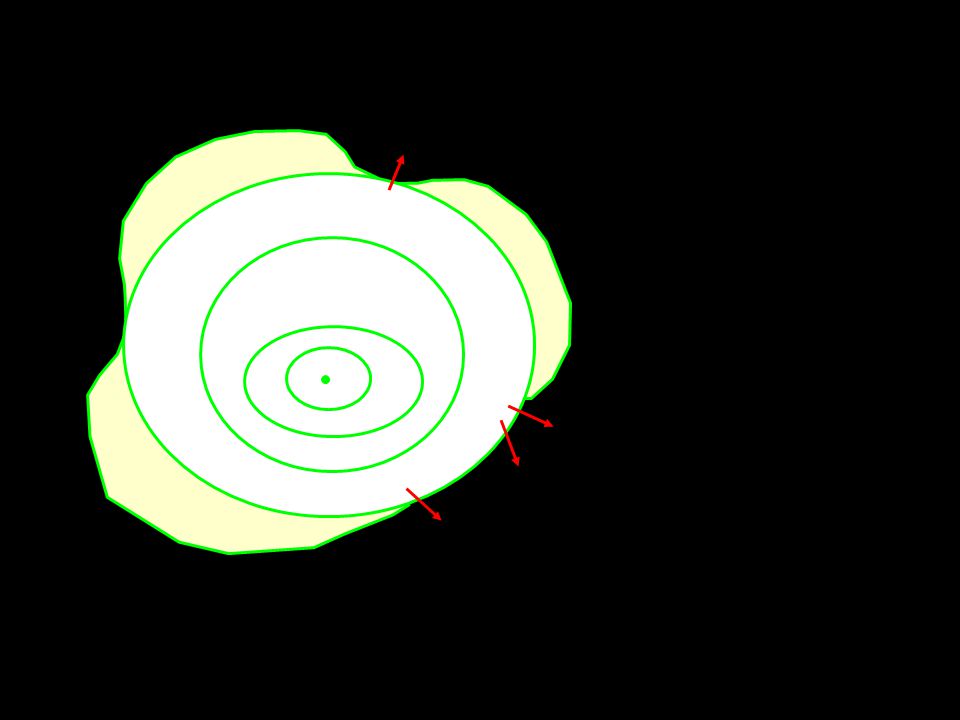
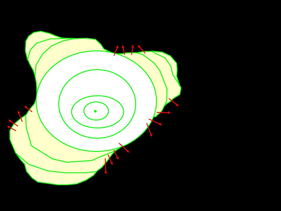
Border of failure states Failure trace Event structure x a b c g d Timing analysis Composition

68
Failure trace Event structure Timing analysis x a b c g d Composition

69
r s t u w

70
r s t u w

71
i j k

72
i j k

73
i j k r s t u w x a b c g d Backannotation (sufficient timing constraints)
")
75
Conclusions An asynchronous circuit is a concurrent system with processes (gates) and communication (wires) The synthesis and formal verification of asynchronous control circuits can be totally automated The theory of concurrency is crucial to formalize automatic synthesis and verification methods Existing tools at academia: petrify, 3D, ATACS, Kronos, versify, etc. Industry starting to try: Intel, Theseus, Cogency, IBM,...

Similar presentations


 A B C Real (analog) behaviorAbstract behavior A B C Abstractions are necessary to define delay models manageable for design, synthesis.>")


 Josep Carmona, UPC (Spain)>")


 Jordi Cortadella (Univ. Politècnica de Catalunya)>")


