Download presentation
Presentation is loading. Please wait.

1
EEE449 Computer Networks Local Area Network (LAN)
")
2
LAN Topology The way in which the end points attached to the network are interconnected Common topologies are bus, tree, ring and star

3
LAN Topologies

4
LAN Topology Bus –Use of a multipoint medium –All stations are attached directly to a linear transmission medium through a tap –Full duplex operation between the station and the tap allows data to be transmitted onto the bus and received from the bus –A transmission from any station propagates the length of the medium in both directions and can be received by all other stations –At each end of the bus is a terminator which absorbs any signal and remove it from the bus

5
LAN Topology Tree –The transmission medium is a branching cable with no closed loops –The layout begins at a point known as the headend –One or more cables start at the headend, and each of these may have branches –The branches in turn may have additional branches –A transmission from any station propagates throughout the medium and can be received by all other stations

6
LAN Topology Ring –The network consists of a set of repeaters joined by point-to-point links in a closed-loop –Links are unidirectional –Each stations attached to the network at a repeater and transmit data onto the network through the repeater –A transmission circulates past all the other stations until it returns to the source station, where it is removed –Need medium access control

7
LAN Topology Star –Each station is directly connected to a common central node typically via two point- to-point links

8
Transmission

10
LAN interconnections Bridges and routers interconnect LANs and connect LAN to WAN Bridge for interconnecting LANs Routers – interconnecting variety of LANs and WANs Bridge –Between LANs that use identical protocols for the physical and link layers reasons for use: reliability, performance, security, geography

11
LAN interconnect

12
LAN interconnections Bridge –no modification to frame content or format –no encapsulation –exact bitwise copy of frame –Large buffer space for minimal buffering to meet peak demand –contains routing and address intelligence –may connect more than two LANs –bridging is transparent to stations

13
LAN interconnections Router –Connect two networks that may or may not be similar –Employs internet protocol –Network layer (layer 3) device –More later
 device –More later")
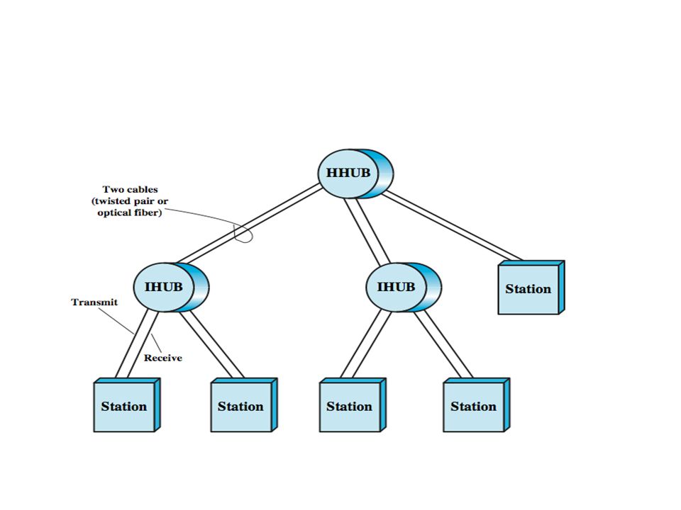
14
LAN interconnections Hubs –active central element of star layout –each station connected to hub by two lines –hub acts as a repeater –limited to about 100 m –optical fiber may be used out to 500m –Can have multiple levels involving a header hub and intermediate hubs

16
LAN interconnections Layer 2 switches –Has replaced hub in popularity particularly for high-speed LANs –aka a switching hub –Multiplying capacity of LAN –store-and-forward switch accepts frame on input line, buffers briefly, routes to destination port see delay between sender and receiver better integrity –cut-through switch use destination address at beginning of frame switch begins repeating frame onto output line as soon as destination address recognized highest possible throughput risk of propagating bad frames

17
LAN interconnections

18
Layer 2 switches –no change to attached devices to convert bus LAN or hub LAN to switched LAN e.g. Ethernet LANs use Ethernet MAC protocol –have dedicated capacity equal to original LAN –scales easily additional devices attached to switch by increasing capacity of layer 2

19
LAN interconnections Layer 3 switch –Implements packet-forwarding function of the router in hardware –packet by packet operates like a traditional router –flow-based switch enhances performance by identifying flows of IP packets with same source and destination by observing ongoing traffic or using a special flow label in packet header (IPv6) a predefined route is used for identified flows to speed up flow
 a predefined route is used for identified flows to speed up flow")
20
LAN interconnections

21
LAN Protocol

22
Includes physical, MAC and LLC layers Physical layer – –Encompasses topology and transmission medium MAC –Control access to the medium for an orderly and efficient use of the capacity –Centralised or decentralised control –Synchronous (dedicated capacity) or asynchronous (on demand) –Synchronous access is not suitable for LAN due to unpredictable station demand
 or asynchronous (on demand) –Synchronous access is not suitable for LAN due to unpredictable station demand")
23
LAN Protocol MAC –Asynchronous access can be based on round robin, reservation or contention Round robin –Efficient when many stations have data to transmit over an extended period of time –Considerable overhead in passing turns when only few stations transmit

24
LAN Protocol Reservation –Time on the medium is divided into slots –Stations can reserved future slots –Suitable for streaming Contention –All stations contend for the time slots –Suitable for bursty traffic

25
LAN Protocol LLC –transmission of link level PDUs between stations –must support multiaccess, shared medium –but MAC layer handles link access details –addressing involves specifying source and destination LLC users referred to as service access points (SAP) typically higher level protocol
 typically higher level protocol")
26
LAN protocol

27
Bridge protocol IEEE 802.1D Station address is designated at the MAC level bridge does not need LLC layer can pass frame over external comms system –capture frame –encapsulate it –forward it across link –remove encapsulation and forward over LAN link –e.g. WAN link

28
Bridge protocol

29
High-Speed LANs –Ethernet (IEEE 802.3 10-Mbps) –Fast Ethernet (IEEE 802.3 100-Mbps) –Gigabit Ethernet –10-Gbps Ethernet
 –Fast Ethernet (IEEE Mbps) –Gigabit Ethernet –10-Gbps Ethernet")
30
Ethernet most widely used LAN standard developed by IEEE 802.3 IEEE 802.3 MAC – use CSMA/CD –Station continues to listen to the medium while transmitting –If the medium is idle, transmit –Otherwise if the medium is busy, continue to listen until the channel is idle and then transmit immediately –If a collision is detected during transmission, transmit a brief jamming signal to assure that all stations know that there has been a collision and then cease transmission –After transmitting the jamming signal, wait a random amount of time (Backoff) then attempt to transmit again
 then attempt to transmit again")
31
Ethernet

32
Preamble: A 7-octet pattern of alternating 0s and 1s used by the receiver to establish bit synchronization. Start Frame Delimiter (SFD): The sequence 10101011, which indicates the actual start of the frame and enables the receiver to locate the first bit of the rest of the frame. Destination Address (DA): Specifies the station(s) for which the frame is intended. It may be a unique physical address, a group address, or a global address. Source Address (SA): Specifies the station that sent the frame. Length/Type: Length of LLC data field in octets, or Ethernet Type field, LLC Data: Data unit supplied by LLC. Pad: Octets added to ensure that the frame is long enough for proper CD operation. Frame Check Sequence (FCS): A 32-bit cyclic redundancy check, based on all fields except preamble, SFD, and FCS.
: The sequence , which indicates the actual start of the frame and enables the receiver to locate the first bit of the rest of the frame. Destination Address (DA): Specifies the station(s) for which the frame is intended. It may be a unique physical address, a group address, or a global address. Source Address (SA): Specifies the station that sent the frame. Length/Type: Length of LLC data field in octets, or Ethernet Type field, LLC Data: Data unit supplied by LLC. Pad: Octets added to ensure that the frame is long enough for proper CD operation. Frame Check Sequence (FCS): A 32-bit cyclic redundancy check, based on all fields except preamble, SFD, and FCS..")
33
Ethernet IEEE 802.3 10Mbps

34
Ethernet IEEE 802.3 10Mbps Alternatives for 10-Mbps are: 10BASE5: Specifies the use of 50-ohm coaxial cable and Manchester digital signaling. The maximum length of a cable segment is set at 500 meters. Can extend using up to 4 repeaters. 10BASE2: lower-cost alternative to 10BASE5 using a thinner cable, with fewer taps over a shorter distance than the 10BASE5 cable. 10BASE-T: Uses unshielded twisted pair in a star-shaped topology, with length of a link is limited to 100 meters. As an alternative, an optical fiber link may be used out to 500 m. 10BASE-F: Contains three specifications using optical fibre

35
Fast Ethernet (IEEE 802.3 100Mbps) a low-cost, Ethernet-compatible LAN operating at 100 Mbps All of the 100BASE-T options use the IEEE 802.3 MAC protocol and frame format.
 a low-cost, Ethernet-compatible LAN operating at 100 Mbps All of the 100BASE-T options use the IEEE MAC protocol and frame format.")
36
Fast Ethernet (IEEE 802.3 100Mbps) 100BASE-X refers to a set of options that use two physical links between nodes; one for transmission and one for reception. 100BASE-TX makes use of shielded twisted pair (STP) or high-quality (Category 5) unshielded twisted pair (UTP). 100BASE-FX uses optical fiber. For all of the 100BASE-T options, the topology is similar to that of 10BASE-T, namely a star-wire topology.
 or high-quality (Category 5) unshielded twisted pair (UTP). 100BASE-FX uses optical fiber. For all of the 100BASE-T options, the topology is similar to that of 10BASE-T, namely a star-wire topology..")
37
Gigabit Ethernet defines a new medium and transmission specification retains the CSMA/CD protocol and Ethernet format of its 10-Mbps and 100-Mbps predecessors. compatible with 100BASE-T and 10BASE-T, preserving a smooth migration path. As more organizations move to 100BASE-T, putting huge traffic loads on backbone networks, demand for Gigabit Ethernet has intensified.

38
Gigabit Ethernet A 1-Gbps switching hub provides backbone connectivity for central servers and high-speed workgroup hubs. Each workgroup LAN switch supports both 1-Gbps links, to connect to the backbone LAN switch and to support high-performance workgroup servers, and 100-Mbps links, to support high-performance workstations, servers, and 100-Mbps LAN switches.

39
Gigabit Ethernet

40
1000BASE-SX: This short-wavelength option supports duplex links of up to 275 m using 62.5-µm multimode or up to 550 m using 50-µm multimode fiber. Wavelengths are in the range of 770 to 860 nm. 1000BASE-LX: This long-wavelength option supports duplex links of up to 550 m of 62.5-µm or 50-µm multimode fiber or 5 km of 10-µm single- mode fiber. Wavelengths are in the range of 1270 to 1355 nm. 1000BASE-CX: This option supports 1-Gbps links among devices located within a single room or equipment rack, using copper jumpers (specialized shielded twisted-pair cable that spans no more than 25 m). Each link is composed of a separate shielded twisted pair running in each direction. 1000BASE-T: This option makes use of four pairs of Category 5 unshielded twisted pair to support devices over a range of up to 100 m.
. Each link is composed of a separate shielded twisted pair running in each direction. 1000BASE-T: This option makes use of four pairs of Category 5 unshielded twisted pair to support devices over a range of up to 100 m..")
41
10-Gbps Ethernet Higher-capacity backbone pipes will help relieve congestion for workgroup switches, where Gigabit Ethernet uplinks can easily become overloaded, and for server farms, where 1-Gbps network interface cards are already in widespread use. The goal for maximum link distances cover a range of applications: from 300 m to 40 km

Similar presentations

 High-Speed LANs. 2 Introduction Fast Ethernet and Gigabit Ethernet Fast Ethernet and Gigabit Ethernet Fibre Channel Fibre Channel High-speed.>")

 Pearson Education.>")


 Internetworking.>")

 Hai Tao.>")
 Andres Rengifo Copyright 2008.>")
>")


 ALOHA Slotted ALOHA CSMA CSMA/CD Token Ring /FDDI Fiber Channel Fiber Channel Protocol.>")

>")
 © Abdou Illia, Spring 2007.>")