Download presentation
Presentation is loading. Please wait.

1
Outline Revisit Analog Modulation Schemes Amplitude Modulation (AM) Frequency Modulation (FM) Analog-to-Digital Conversion - Sampling Digital Modulation Schemes
 Frequency Modulation (FM) Analog-to-Digital Conversion - Sampling Digital Modulation Schemes")
2
Modulation Process Information-bearing signals (e.g., voice, video) are called baseband signals. Other terms for information-bearing signals are message signal and modulating wave. Modulation is defined as the process by which some characteristics of a carrier signal (typically a cosine wave) is varied in accordance with a message signal. Modulation process is required to shift the frequency content of our message signals to a range that is acceptable by the transmission medium. (e.g., above 30 KHz for wireless transmission).
 is varied in accordance with a message signal. Modulation process is required to shift the frequency content of our message signals to a range that is acceptable by the transmission medium. (e.g., above 30 KHz for wireless transmission)..")
3
Modulation Types Analog Modulation:Digital Modulation: Message signal is analog (a.k.a continuous-time). Message signal is digital (a.k.a discrete-time). Amplitude Modulation (AM) Frequency Modulation (FM) Phase Modulation (PM) Amplitude Shift Keying (ASK) Frequency Shift Keying (FSK) Phase Shift Keying (PSK)
. Amplitude Modulation (AM) Frequency Modulation (FM) Phase Modulation (PM) Amplitude Shift Keying (ASK) Frequency Shift Keying (FSK) Phase Shift Keying (PSK).")
4
Digital Modulation Schemes

5
Figure 4-8 WCB/McGraw-Hill The McGraw-Hill Companies, Inc., 1998 Amplitude Change

6
Figure 4-9 WCB/McGraw-Hill The McGraw-Hill Companies, Inc., 1998 Frequency Change

7
Figure 4-10 WCB/McGraw-Hill The McGraw-Hill Companies, Inc., 1998 Phase Change

8
Figure 5-24 WCB/McGraw-Hill The McGraw-Hill Companies, Inc., 1998 Amplitude Shift Keying Also known as Symbol Rate

9
Frequency Shift Keying Figure 5-27 WCB/McGraw-Hill The McGraw-Hill Companies, Inc., 1998

10
Phase Shift Keying Figure 5-29 WCB/McGraw-Hill The McGraw-Hill Companies, Inc., 1998

11
PSK Constellation Figure 5-30 WCB/McGraw-Hill The McGraw-Hill Companies, Inc., 1998

12
Quadrature PSK - QPSK 4-PSK Figure 5-31 WCB/McGraw-Hill The McGraw-Hill Companies, Inc., 1998

13
QPSK Constellation Figure 5-32 WCB/McGraw-Hill The McGraw-Hill Companies, Inc., 1998

14
8-PSK Constellation Figure 5-33 WCB/McGraw-Hill The McGraw-Hill Companies, Inc., 1998

15
4-QAM and 8-QAM Constellations Figure 5-35 WCB/McGraw-Hill The McGraw-Hill Companies, Inc., 1998

16
8-QAM Signal Figure 5-36 WCB/McGraw-Hill The McGraw-Hill Companies, Inc., 1998

17
16-QAM Constellation Figure 5-37 WCB/McGraw-Hill The McGraw-Hill Companies, Inc., 1998

18
Figure 5.17 Bit and baud

19
Table 5.1 Bit and baud rate comparison ModulationUnitsBits/Baud Baud rate Bit Rate ASK, FSK, 2-PSK Bit1NN 4-PSK, 4-QAM Dibit2N2N 8-PSK, 8-QAM Tribit3N3N 16-QAMQuadbit4N4N 32-QAMPentabit5N5N 64-QAMHexabit6N6N 128-QAMSeptabit7N7N 256-QAMOctabit8N8N

20
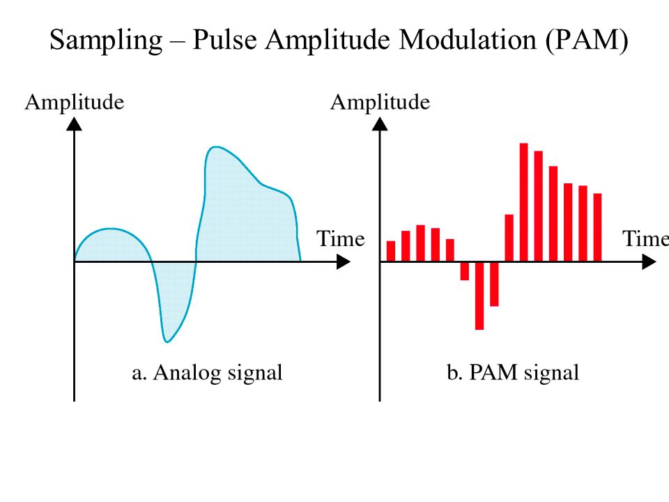
Sampling – Pulse Amplitude Modulation (PAM)
")
22
Quantized PAM Signal

23
Figure 3.11 Illustration of the quantization process. (Adapted from Bennett, 1948, with permission of AT&T.)
.")
24
Figure 5-20-continued WCB/McGraw-Hill The McGraw-Hill Companies, Inc., 1998 From Analog to PCM

25
Figure 5-20-continued WCB/McGraw-Hill The McGraw-Hill Companies, Inc., 1998 From Analog to PCM

26
Figure 5-20-continued WCB/McGraw-Hill The McGraw-Hill Companies, Inc., 1998 From Analog to PCM

27
Figure 5-19 WCB/McGraw-Hill The McGraw-Hill Companies, Inc., 1998 Pulse Coded Modulation

28
Nyquist’s Sampling Theorem A band-limited signal of finite energy, which has no frequency components higher than W Hertz, may be completely described by specifying the values of the signal at instants of time separated by (1/2W) seconds or can be recovered from a knowledge of its samples taken at a rate of 2W samples per second. f s = 2 × W Sampling frequency Bandwidth of signal

29
Impact of Sampling on the Frequency Domain Sampling frequency = message bandwidth Message signal cannot be recovered from the sampled signal !!

30
Impact of Sampling on the Frequency Domain Message signal Frequency Content Frequency Content of the sampled message signal Sampling frequencyMessage bandwidth f s = 2 × W

31
Revisit Analog Modulation Schemes Amplitude Modulation (AM) Frequency Modulation (FM) How to produce AM Signal?
 Frequency Modulation (FM) How to produce AM Signal")
32
Amplitude Modulation

33
Carrier Signal: Message Signal or modulating signal: Modulated Signal: Modulation Index vS(t)vS(t) vCvC cos C t Modulating signal Carrier AmplitudeCarrier Frequency V AM (t)
vS(t) vCvC cos C t Modulating signal Carrier AmplitudeCarrier Frequency V AM (t)")
34
Amplitude Modulation Modulation Index M is determined by the peak amplitudes of the carrier and the modulating signal. In practice, carrier signal amplitude v C is usually fixed and the M ratio is changed by varying the amplitude of the modulating signal v S. Hence, higher v S produce higher M but M < 1. M is kept as high as possible to ensure good SNR of the received AM signal for recovery. When M > 1, over-modulated carrier signal distorts the information – Clipping or saturation.

35
Amplitude Modulation Illustrating the amplitude modulation process. (a) Baseband signal v s (t). (b) AM wave for M 1 for some t. Envelope of the modulated signal has the same shape with the message signal. Envelope is distorted
 Baseband signal v s (t). (b) AM wave for M 1 for some t. Envelope of the modulated signal has the same shape with the message signal. Envelope is distorted.")
36
AM : Double-sided band (DSB) where modulating signal: AM Signal: Thus, Carrier Component Lower side band (LSB) Double-side band components (DSB) Upper side band (USB) Wasted energy in carrier component because it contains no information Action: To suppress the carrier
 where modulating signal: AM Signal: Thus, Carrier Component Lower side band (LSB) Double-side band components (DSB) Upper side band (USB) Wasted energy in carrier component because it contains no information Action: To suppress the carrier")
37
Amplitude Modulation AM is the earliest type of modulation in history. Its main advantage is its simplicity. – linear modulation technique AM is wasteful in power consumption. Although the carrier signal does not carry any information, it is still transmitted. AM is wasteful in bandwidth usage. The upper sideband is reflection of the lower sideband. One sideband is sufficient to express the frequency content of the message signal. Yet, AM still transmits one unnecessary sideband.

38
Spectrum of AM wave fcfc f f c +f S f c -f S |v||v| fSfS fcfc f f c +f S f c -f S |v||v| (a) Spectrum of AM Signal: both carrier and double-sided bands (b) Spectrum of Double-Sided Band - Carrier Suppression (DSB-SC)
 Spectrum of AM Signal: both carrier and double-sided bands (b) Spectrum of Double-Sided Band - Carrier Suppression (DSB-SC)")
39
Double Sideband-Suppressed Carrier Modulation (DSB-SC) cos C t Modulating signal Carrier Frequency DSB-SC signal Balance Modulator -90 o vS(t)vS(t) vC(t)vC(t) DSB-SC Carrier Oscillator vS(t)vS(t)
 cos C t Modulating signal Carrier Frequency DSB-SC signal Balance Modulator -90 o vS(t)vS(t) vC(t)vC(t) DSB-SC Carrier Oscillator vS(t)vS(t)")
40
Double Sideband-Suppressed Carrier Modulation (DSB-SC) modulating signal: DSB-SC signal:
 modulating signal: DSB-SC signal:")
41
Single Sideband-Suppressed Carrier Modulation (SSB-SC) cos C t Modulating signal Carrier Frequency DSB-SC signal vS(t)vS(t) Sideband filter (crystal filter) SSB-SC signal Bandpass filter applied at the DSB-SC signal to generate SSB-SC signal. Problem: It is very difficult and costly to design a bandpass filter that is sharp enough to select only one sideband !

42
Demodulation of AM signal cos C t Modulating signal Carrier Frequency DSB-SC signal Balance Modulator -90 o vS(t)vS(t) vC(t)vC(t) DSB-SC Carrier Oscillator
vS(t) vC(t)vC(t) DSB-SC Carrier Oscillator")
43
Demodulation of AM signal Most basic: Envelope detector (for AM signal only) diode D + – R C AM signal v AM (t) As V AM (t) increases in amplitude, the diode conducts (forward bias) and capacitor C start to charge-up very quickly to 1 st peak v p1 with a time constant = Cr, where r is the diode’s forward resistance (usually very small when diode is conducting). As V AM (t) decreases in amplitudes, the diode switch-off (reverse bias) and capacitor C start to discharge slowly with a time constant = CR, where R must be greater than r. When V AM (t) increases again, D conducts and C charges up rapidly to 2 nd peak v p2 and when V AM (t) decreases again D is off and C discharges slowly and this is repeated according to the amplitude of V AM (t) signal. If CR is too small, C discharge too rapidly; results in ripple amplitude in demodulated output. If CR is too large, C discharge too slowly; vs(t) fails to follow the envelope results in distortion (or diagonal clippling) in demodulated output. Hence, time constant must be optimum. Charging/Discharging voltage vs(t)vs(t) CcCc To remove DC component & smoothen v s (t)
 decreases in amplitudes, the diode switch-off (reverse bias) and capacitor C start to discharge slowly with a time constant = CR, where R must be greater than r. When V AM (t) increases again, D conducts and C charges up rapidly to 2 nd peak v p2 and when V AM (t) decreases again D is off and C discharges slowly and this is repeated according to the amplitude of V AM (t) signal. If CR is too small, C discharge too rapidly; results in ripple amplitude in demodulated output. If CR is too large, C discharge too slowly; vs(t) fails to follow the envelope results in distortion (or diagonal clippling) in demodulated output. Hence, time constant must be optimum. Charging/Discharging voltage vs(t)vs(t) CcCc To remove DC component & smoothen v s (t).")
44
Optimum AM Demodulation Ripple amplitude in AM Demodulation – RC too small Diagonal Clipping/distortion in AM Demodulation – RC too large

45
Demodulation of (DSB-SC) signal (1) cos C t DSB-SC signal local oscillator Recovered modulating signal Synchronous detection Low Pass Filter Local oscillator produce the exactly coherent oscillation output that is synchronized with the original carrier in both frequency and phase. The output is then filter by low-pass filter that only allowed the desired signal to pass through. fcfc f f c +f S f c -f S |v||v| fSfS Desired signal Unwanted signal

46
Demodulation of (DSB-SC) signal (2) Costal Loop / Phase Lock Loop (PLL) -90 o DSB-SC VCO Loop filter LPF Output: The frequency f c is know a priori to the demodulator and generated by the voltage control oscillator, VCO. PLL circuit (VCO + Loop filter) try to lock the phase so that local oscillation is synchronized with original f c. of the DSBSC signal. Once synchronization is achieved, the difference in phase will be eliminated, thereby, recover the modulating signal.
 try to lock the phase so that local oscillation is synchronized with original f c. of the DSBSC signal. Once synchronization is achieved, the difference in phase will be eliminated, thereby, recover the modulating signal..")
47
Frequency Modulation (FM) In FM, the information is conveyed by varying the frequency of the carrier signal f C in step with the instantaneous amplitude of the modulating signal v s. vsvs fCfC fifi

48
FM signal is produced by a frequency modulator which converts the voltage variation in the modulating signal v s to a frequency variation of the carrier signal The “instantaneous” frequency f i is the sum of carrier frequency f C and the “frequency deviation” as the result of the ‘amplitude-frequency’ conversion. Frequency Modulation (FM) Frequency Modulator vs(t)vs(t) fifi When no modulating signal is applied, the output frequency is the same as the carrier frequency since ; no deviation is observed. When a modulating signal is applied, the instantaneous output frequency f i will start to vary/deviate from f c with the amount of. The conversion can be seen from the graph fcfc fifi vsvs 0 k f = Conversion gain
 Frequency Modulator vs(t)vs(t) fifi When no modulating signal is applied, the output frequency is the same as the carrier frequency since ; no deviation is observed. When a modulating signal is applied, the instantaneous output frequency f i will start to vary/deviate from f c with the amount of. The conversion can be seen from the graph fcfc fifi vsvs 0 k f = Conversion gain.")
49
Frequency Modulation (FM) Fact in FM : Instantaneous frequency f i of the cosine wave is: 11 22 FM Modulated Signal: Carrier Signal: (Distance = speed × time) Angular displacement : Constant speed varying speed Instantaneous angular displacement
 Fact in FM : Instantaneous frequency f i of the cosine wave is: 11 22 FM Modulated Signal: Carrier Signal: (Distance = speed × time) Angular displacement : Constant speed varying speed Instantaneous angular displacement")
50
Frequency Modulation (FM) General FM signal can be expressed as: Recall that instantaneous frequency i of FM: where i is the instantaneous angular displacement: hence i can be re-written as: FM modulation index:
 General FM signal can be expressed as: Recall that instantaneous frequency i of FM: where i is the instantaneous angular displacement: hence i can be re-written as: FM modulation index:")
51
Frequency Modulation (FM) Therefore, FM signal can be expressed as: FM modulation index: Carrier frequency is varied or deviated by the amount of controls the amount of frequency change in FM signal. In FM, can be greater than 1: ( > 1), since can be set independent of f s and both values are not bounded by f C. However, f s must be kept smaller than f C in order for FM to work successfully. FM is a non-linear modulation. FM signal envelope is constant.
, since can be set independent of f s and both values are not bounded by f C. However, f s must be kept smaller than f C in order for FM to work successfully. FM is a non-linear modulation. FM signal envelope is constant..")
52
Frequency Modulation Carson’s Rule: The transmission bandwidth required by a frequency modulated signal is given below. Maximum frequency deviation FM modulation index:

53
Example A message signal with a bandwidth of 15 KHz is to be used to frequency modulate a carrier signal at 400 KHz. Given that maximum frequency deviation is 75 KHz. According to Carson’s Rule, what is the transmission bandwidth required for the frequency modulated signal? 1) message bandwidth ? 2) maximum frequency deviation ? 3) modulation index ? 4) Using Carson’s rule, the required transmission bandwidth:
 message bandwidth . 2) maximum frequency deviation . 3) modulation index . 4) Using Carson’s rule, the required transmission bandwidth:.")
54
Tutorial 1- What is Amplitude Modulation ? Amplitude modulation is the process by which the amplitude of a carrier signal is varied according to a message signal. 2- What frequency range will be covered by a 412 KHz carrier signal after it has been amplitude modulated by an audio signal that is bandlimited to 24 KHz ? Due to amplitude modulation, the frequency spectrum of the audio signal will shift to the carrier signal frequency. The frequency range from (412-24) KHz to (412+24) KHz will be covered by the amplitude modulated signal.
 KHz to (412+24) KHz will be covered by the amplitude modulated signal..")
55
Tutorial 3- Consider the video signal that has a frequency content between 0 Hz and 6 MHz. What is the required transmission bandwidth if Frequency Modulation is used with a maximum frequency deviation of 30 MHz according to Carson’s Rule ? maximum frequency deviation ? modulation index ?

56
With aid of diagram, explain the process of amplitude modulation? Your answer should include the carrier signal, modulating signal and the AM signal itself. Tutorial

57
4- What is Amplitude Shift Keying (ASK)? ASK is a digital modulation technique where the amplitude of a carrier signal is varied to transmit ones and zeros. 5- What is Phase Shift Keying (PSK)? PSK is a digital modulation technique where the phase of a carrier signal is varied to transmit ones and zeros. 6- What is Frequency Shift Keying (FSK)? FSK is a digital modulation technique where the frequency of a carrier signal is varied to transmit ones and zeros.
. PSK is a digital modulation technique where the phase of a carrier signal is varied to transmit ones and zeros. 6- What is Frequency Shift Keying (FSK). FSK is a digital modulation technique where the frequency of a carrier signal is varied to transmit ones and zeros..")
58
Tutorial 7- Sketch the ASK modulated signal for a bit pattern of 01100101. Use a cosine wave as the carrier signal!

59
Tutorial 8- Sketch the PSK modulated signal for a bit pattern of 01100101. Use a cosine wave as the carrier signal!

60
Tutorial Briefly explain the Pulse Amplitude Modulation (PAM) and Quantisation process. PAM converts the analog signal to a series of pulse-trains with different amplitude corresponding to the amplitude of the analog signal at different interval in time. Quantisation is a process to convert these pulse-trains amplitude from analog value to discrete value by binary level representation. The number levels (L) that can be represented is corresponding to the number of bit (N) used. L = 2 N
 that can be represented is corresponding to the number of bit (N) used. L = 2 N.")
61
Tutorial With the aid of block diagram, describe how a analog signal is sent using a digital system with PAM.

Similar presentations


 ANGLE MODULATION>")
>")

 3.Frequency Shift Keying (FSK) 4.Phase Shift Keying (PSK) 5.Quadrature.>")


 ©2003 Glencoe/McGraw-Hill Charles A. Schuler.>")