Download presentation
Presentation is loading. Please wait.

1
Recent Beam-Beam Simulation for PEP-II Yunhai Cai December 13, 2004 PEP-II Machine Advisory Committee Meeting at SLAC

2
Acknowledgment Beam-beam study group: John Seeman (PEP-II, SLAC) Witold Kozanecki (PEP-II, BaBar) Ilya Narsky (BaBar, Caltech) Frank Porter (BaBar, Caltech) Nonlinear map: Yiton Yan (ARDA, SLAC) Benchmark codes: Kazuhito Ohmi (KEKB) Masafumi Tawada (KEKB) Joe Rogers (CESR, Cornell) Outline New PC cluster Nonlinear maps Closed orbit and tune shift due to parasitic collision Crossing angle and parasitic collision Intensity Year of 2007 Conclusion
 Witold Kozanecki (PEP-II, BaBar) Ilya Narsky (BaBar, Caltech) Frank Porter (BaBar, Caltech) Nonlinear map: Yiton Yan (ARDA, SLAC) Benchmark codes: Kazuhito Ohmi (KEKB) Masafumi Tawada (KEKB) Joe Rogers (CESR, Cornell) Outline New PC cluster Nonlinear maps Closed orbit and tune shift due to parasitic collision Crossing angle and parasitic collision Intensity Year of 2007 Conclusion")
3
SLAC PC FARM Linux cluster interconnected with 64-bit PCI-X (PCIXD, Lanai X) Myrinet 2000. All nodes are 2.6GHz dual- Xeon Pentium IV Rackable systems running RHEL 3.0. These are 128 of our 384 node Linux cluster. 20% faster than seaborg at NERSC for beam-beam simulation using 32 processors. We own 25% of the cluster.

4
Scaling on Parallel Supercomputers Recently, SLAC has installed a Linux clusters with 128 processors. We have high priority on the cluster because of our contribution $50,000 to the purchase. SP(IBM), T3E(CRAY), ALVAREZ (LINUX PC) are the super computers at NERSC. We gain a factor of 24 In speed with 32 processors on the SP.
, T3E(CRAY), ALVAREZ (LINUX PC) are the super computers at NERSC. We gain a factor of 24 In speed with 32 processors on the SP..")
5
Main Features in the Code: Beam- Beam Interaction (BBI) Arbitrary beam distributions Precision Poisson solver for the core Equal-spacing or equal-area longitudinal slices Linear interpolation between the slices Numerical convergence in all three dimensions Radiation damping and quantum excitation Linear or nonlinear map for the lattices Gaussian beam-beam kicks Parallel supercomputing with 32 processors Crossing angle and parasitic collisions Object-oriented in C++ with MPI library
 Arbitrary beam distributions Precision Poisson solver for the core Equal-spacing or equal-area longitudinal slices Linear interpolation between the slices Numerical convergence in all three dimensions Radiation damping and quantum excitation Linear or nonlinear map for the lattices Gaussian beam-beam kicks Parallel supercomputing with 32 processors Crossing angle and parasitic collisions Object-oriented in C++ with MPI library")
6
PEP-II with a Crossing Angle October 9, 2003 For a half angle of 3.0 mrad, we see a degradation of luminosity by 43%. Similar results have been obtained by Ohmi and Tawada using their code.

7
Luminosity Reduction due to Parasitic Collisions April 15, 2004 The smaller y makes more degradation to the luminosity In terms of the absolute values but not in relative ones. The reduction is about 7% in both cases. With 1412 bunches, we can achieve 1x10 34 cm -2 s -1 when * y = 7mm without Increasing beam currents. 7.125x10 30 cm -2 s -1

8
Comparison of map and element- by-element tracking (5 y /step) 6 th order 8 th order Taylor map (Zlib) Mix-variable generating function (Zlib) element-by-element tracking (LEGO)
 6 th order 8 th order Taylor map (Zlib) Mix-variable generating function (Zlib) element-by-element tracking (LEGO)")
9
ParametersDescription(5/21/2004)LER(e + )HER(e - ) E(Gev)beam energy3.19.0 Nbunch population6.97x10 10 (1.52mA) 4.40x10 10 (0.96mA) x * (cm) beta x at the IP3232.0 y * (cm) beta y at the IP1.05 x (nm-rad) emittance x22.059.0 y (nm-rad) emittance y1.401.30 x x tune0.51620.5203 y y tune0.56390.6223 s synchrotron tune0.0290.049 z (cm) bunch length1.301.15 pp energy spread6.5x10 -4 6.1x10 -4 t (turn) transverse damping time98005030 l (turn) longitudinal damping time48002573
LER(e + )HER(e - ) E(Gev)beam energy Nbunch population6.97x10 10 (1.52mA) 4.40x10 10 (0.96mA) x * (cm) beta x at the IP y * (cm) beta y at the IP1.05 x (nm-rad) emittance x y (nm-rad) emittance y x x tune y y tune s synchrotron tune z (cm) bunch length pp energy spread6.5x x10 -4 t (turn) transverse damping time l (turn) longitudinal damping time")
10
PEP-II Parasitic Collisions May 21, 2004 crossing[m] x[mm]# of (e+)# of (e-) 0.320.10.840.51 0.633.2217.3810.61 0.959.6936.8722.51 1.2617.7852.1631.85 1.5828.8668.2841.69 1.8943.686.7552.97 2.2160.53103.3863.13 2.5277.61116.5271.15 2.8494.73126.4177.19 3.15112.31135.2882.61
![PEP-II Parasitic Collisions May 21, 2004 crossing[m] x[mm]# of (e+)# of (e-)](http://images.slideplayer.com/16/5191048/slides/slide_10.jpg "PEP-II Parasitic Collisions May 21, 2004 crossing[m] x[mm]# of (e+)# of (e-)")
11
Head-on Collision and Parasitic Collisions Head-on collision is calculated with particle-in- cell method Gaussian approximation is used for parasitic crossing and beam size is updated every 1000 turns Only the nearest parasitic crossings are included Drift is used between the parasitic collisions and head-on collision Tune shift from parasitic collision xx

12
Tune Shift Due to Parasitic Crossings LER(e+)HER(e-) Horizontal-0.000958-0.000523 Vertical0.0233(0.026)0.0123(0.014) Two nearest parasitic collisions are included in the calculation. Single parasitic collision contributes half of the value.

13
Closed Orbit at the Interaction point due to Parasitic Collisions Horizontal kick: Nominal bunch: IP 2 Packman bunch or e + : 3.81 m, 1.40 rad e - : 2.07 m, 0.78 rad

14
Closed Orbits due to Parasitic Collisions in Beam-Beam Simulation The angles of the orbits are so small that they do change the luminosity in the simulation. x 0 + =x 0 - =0

15
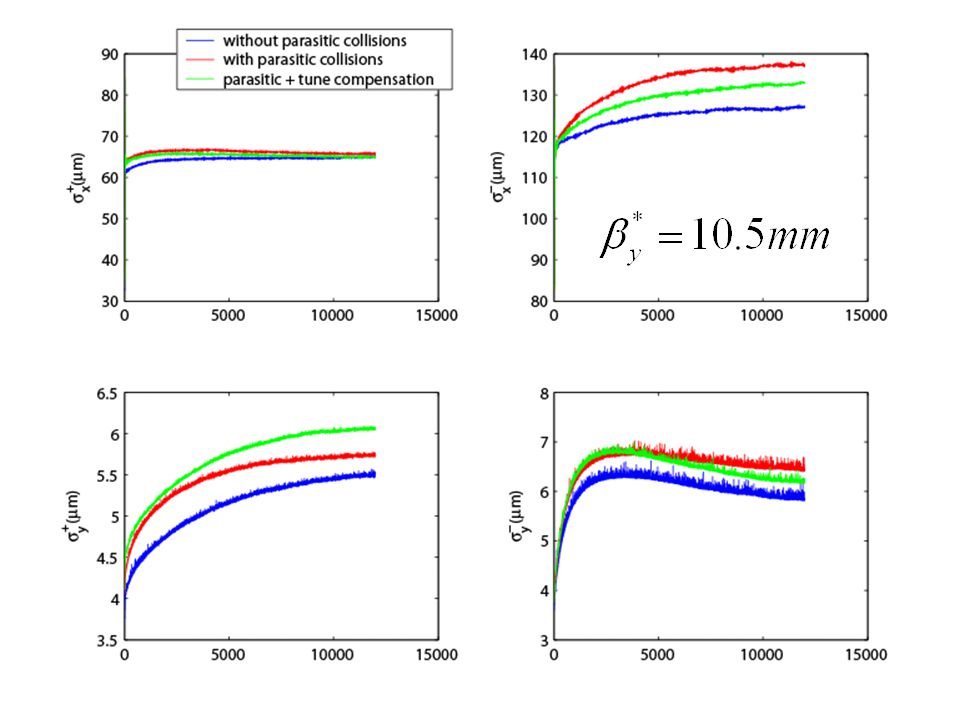
Luminosity Effects of Parasitic Collisions and Its Compensation Luminosity degradation due to parasitic collisions is about 5%. The luminosity degradation can be completely recovered by the tune shifts in vertical plane for the machine parameters, May 21, 2004.

17
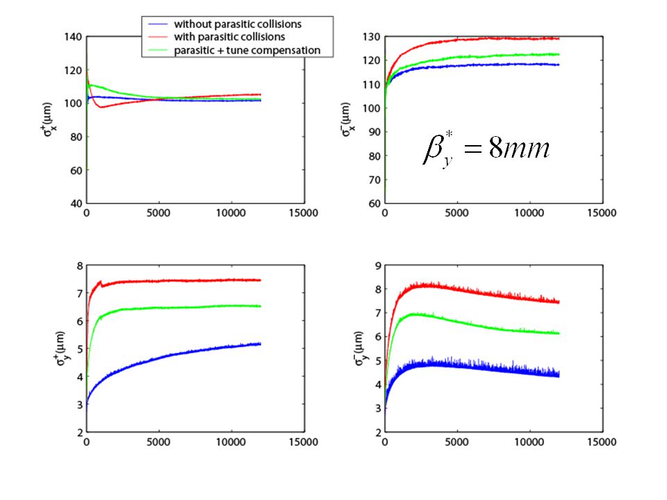
Tune shift can be corrected by resetting the tune when the separation is larger enough compared to the beam size.

18
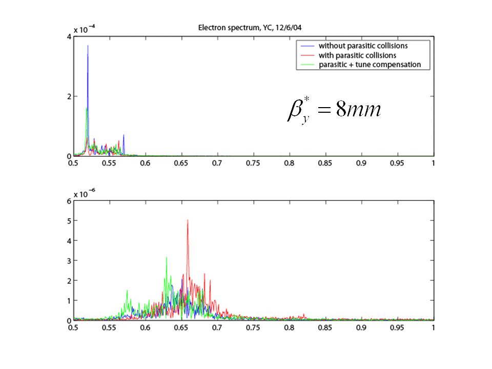
Tune shift seen in the spectrum is consistent with the analytic calculation.

19
Parasitic Collisions and Crossing Angle at PEP-II Compared with the measured luminosity: 5.61 10 30 cm -2 s -1, the simulation result with -0.2mrad is closer.

20
Trade off between Parasitic Collisions and Crossing Angle Best luminosity achieved when the vertical beam sizes are small and matched.

21
Dependency of Beam Currents with Parasitic Collisions and Crossing angle (-0.2mrad) Luminosity Specific Luminosity 8x10 30 5x10 30
 Luminosity Specific Luminosity 8x x10 30")
22
Beam Blowup as Currents Increase with Parasitic Collisions and Crossing Angle (-0.2mrad) Beam-beam scan at low current: Luminous region from BaBar: Blowup of beams:
 Beam-beam scan at low current: Luminous region from BaBar: Blowup of beams:")
23
Beam-Beam Parameters with Parasitic Collisions May 21, 2004: 0.08 0.06 0.20

24
ParametersDescription(2007, Seeman)LER(e + )HER(e - ) E(Gev)beam energy3.19.0 Nbunch population12.03x10 10 (2.62mA) 5.88x10 10 (1.28mA) x * (cm) beta x at the IP2828.0 y * (cm) beta y at the IP0.8 x (nm-rad) emittance x60.0 y (nm-rad) emittance y1.0 x x tune0.51620.5203 y y tune0.56390.6223 s synchrotron tune0.0320.055 z (cm) bunch length0.9 pp energy spread6.5x10 -4 6.1x10 -4 t (turn) transverse damping time98005030 l (turn) longitudinal damping time48002573
LER(e + )HER(e - ) E(Gev)beam energy Nbunch population12.03x10 10 (2.62mA) 5.88x10 10 (1.28mA) x * (cm) beta x at the IP y * (cm) beta y at the IP0.8 x (nm-rad) emittance x60.0 y (nm-rad) emittance y1.0 x x tune y y tune s synchrotron tune z (cm) bunch length0.9 pp energy spread6.5x x10 -4 t (turn) transverse damping time l (turn) longitudinal damping time")
25
PEP-II Parasitic Collisions Year of 2007 crossing[m] x[mm]# of (e+)# of (e-) 0.320.10.51 0.633.2210.09 0.959.6921.14 1.2617.7829.76 1.5828.8638.85 1.8943.649.30 2.2160.5358.70 2.5277.6166.12 2.8494.7371.71 3.15112.3176.72
![PEP-II Parasitic Collisions Year of 2007 crossing[m] x[mm]# of (e+)# of (e-)](http://images.slideplayer.com/16/5191048/slides/slide_25.jpg "PEP-II Parasitic Collisions Year of 2007 crossing[m] x[mm]# of (e+)# of (e-)")
26
Tune Shift Due to Parasitic Crossings Year of 2007 LER(e+)HER(e-) Horizontal-0.00139-0.00098 Vertical0.04060.0286 Two nearest parasitic collisions are included in the calculation. Single parasitic collision contributes half of the value. Values are nearly doubled compared to ones in 2004.

27
Luminosity Degradation due to Parasitic Collisions (Year of 2007) -76% Without parasitic collisions, the total luminosity = 1715x1.51x10 31 cm -2 s -1 = 2.59x10 34 cm -2 s -1 compared to Seeman’s expected value: 2.4x10 34 cm -2 s -1.
 -76% Without parasitic collisions, the total luminosity = 1715x1.51x10 31 cm -2 s -1 = 2.59x10 34 cm -2 s -1 compared to Seeman’s expected value: 2.4x10 34 cm -2 s -1.")
31
Tune and Crossing Angle Compensation for Parasitic Collisions x = 3.85 mm at = -0.5mrad (3.22mm at =0) which is about 12 x separation. Expected luminosity can be achieved with tune compensation and small crossing angle (-2x0.5mrad). 1.55x10 31
. 1.55x")
32
Crossing Angle and More Separation

33
Really Need Crossing Angle? Yes. It helps litter but main gain is from the separation!

34
Future Work Detailed tune scan near half integer tune All possible machine errors, including coupling and dispersions Symplectic tracking of non-linear map Calculate beam-beam lifetime with nonlinear maps & parasitic collisions More study of upgrades scenarios Combined effects of electron cloud and beam-beam

35
Conclusion Progress has been made to symplectify Taylor map. The improvement of computational speed allows us to include machine nonlinearity in the beam-beam simulation. This is critical for beam- beam lifetime calculation. For current parameters, the luminosity degradation due to the parasitic collisions is about 5% which can be simply recovered with a change of the vertical tunes. Our simulation confirms the experimental observation that there is a possible trade off between a larger separation of parasitic collisions and small crossing angle. For 2007 machine parameters, the degradation of luminosity is much large, about 75%. However, the simulation shows that the degradation can be partially recovered by resetting the vertical tunes and full recovery requires further separation of beams at parasitic crossing point to 3.85 mm (12 x ). Under these conditions, the simulation confirms that John’s expected value of luminosity can be achieved.
. Under these conditions, the simulation confirms that John’s expected value of luminosity can be achieved..")
36
Expectations and Suggestions “lowering of x *(50cm->32cm)” in the LER should be backed out because it increases x and beam size at the parasitic collision points and makes beams more mismatched in the head-on collision. We should see stronger effects of parasitic collisions once wigglers is turned on. That implies that we may need to separate beams sooner rather than later. Parasitic collision may prevent us from moving closer to the half integer because the dynamic beta and emittance increase the beam size at parasitic crossings. We suggest to have more experiments to measure these effects and compare them to our simulation.

Similar presentations

 Super B workshop at SLAC 15-17, June 2006 Thanks, M. Biagini, Y. Funakoshi, Y. Ohnishi, K.Oide,>")


 Super B factories workshop in Hawaii 20-23 Apr. 2005.>")


 at High Energies (120, 175 GeV) Dmitry Shatilov BINP, Novosibirsk 11 December 2014, CERN.>")


