Download presentation
Presentation is loading. Please wait.

0
16-bit MS-DOS and BIOS Programming
Department of Computer Science National Tsing Hua University

1
Overview Chapter 13: 16-bit MS-DOS Programming MS-DOS and the IBM-PC
MS-DOS Function Calls (INT 21h) Standard MS-DOS File I/O Services Chapter 15: BIOS-Level Programming Keyboard Input with INT 16h VIDEO and Graphics Mouse Programming How Does a PC Boot?
 Standard MS-DOS File I/O Services. Chapter 15: BIOS-Level Programming. Keyboard Input with INT 16h. VIDEO and Graphics. Mouse Programming. How Does a PC Boot")
2
Assembly Language for Intel-Based Computers, 5th Edition
Kip Irvine Chapter 13: 16-Bit MS-DOS Programming Slides prepared by the author Revision date: June 4, 2006 (c) Pearson Education, All rights reserved. You may modify and copy this slide show for your personal use, or for use in the classroom, as long as this copyright statement, the author's name, and the title are not changed.
 Pearson Education, All rights reserved. You may modify and copy this slide show for your personal use, or for use in the classroom, as long as this copyright statement, the author s name, and the title are not changed.")
3
Real-Address Mode Real-address mode (16-bit mode) programs have the following characteristics: Max 1 megabyte addressable RAM Single tasking No memory boundary protection Offsets are 16 bits IBM PC-DOS: first real-address OS for IBM-PC Has roots in Gary Kildall's highly successful Digital Research CP/M Later renamed to MS-DOS, owned by Microsoft

4
MS-DOS Memory Map

5
MS-DOS Memory Organization
Lowest 640K bytes: used by OS and applications Interrupt Vector Table (1K bytes, – 003FF) BIOS and DOS data Software BIOS MS-DOS kernel Resident command processor (命令提示字元) Transient programs Video graphics and text Reserved (device controllers) ROM BIOS (F0000 to FFFFF)
 BIOS and DOS data. Software BIOS. MS-DOS kernel. Resident command processor (命令提示字元) Transient programs. Video graphics and text. Reserved (device controllers) ROM BIOS (F0000 to FFFFF)")
6
Interrupt If you call your friend and his/her mom says he/she is not home, what do you do? Do something else, and get interrupted when he/she is back and returns your call. When you are interrupted by a phone ring, you must somehow know who is interrupting you and what he/she wants. Based on the type of interrupts, you then do the required operations. After serving the interrupt, you return to the operations before interrupt.

7
Interrupt You may be interrupted by external events, e.g. phone ring, or internal events, e.g. fetch a soda while studying. Analog in processor: Interrupts may be triggered by hardware, e.g. I/O devices, which is outside of your program. Interrupts may also be trigger by software, e.g. program faults or system service calls, which is generated by your program itself. Software interrupt: A call to an OS procedure (interrupt handler), mainly for I/O
, mainly for I/O.")
8
Hardware Interrupts

9
Hardware Device Initialization
At startup, a hardware device is assigned: An IRQ by which it can signal the CPU that it needs attention Some I/O addresses by which the CPU and the device can communicate Some memory addresses that indicate where the program to manage the device can be stored Perhaps a DMA channel to speed up sending its data to memory

10
Software Interrupts

11
INT Instruction Executes a software interrupt to request MS-DOS services The code that handles the interrupt is called an interrupt handler (or interrupt service routine (ISR)) Syntax: The Interrupt Vector Table (IVT) maps an interrupt number to a 32-bit segment-offset address for each interrupt handler. INT number (number = 0..FFh)
) Syntax: The Interrupt Vector Table (IVT) maps an interrupt number to a 32-bit segment-offset address for each interrupt handler. INT number (number = 0..FFh)")
12
INT Vectors In Interrupt Vector Table in 00000h-003FFh (1KB)
For the execution of INT 00-FF Each INT uses a 4-byte vector (CS:IP): 2 bytes for IP 2 bytes for CS Actual code (Service Routine) is in CS:IP IRET at the end of INT Service Routine
: 2 bytes for IP. 2 bytes for CS. Actual code (Service Routine) is in CS:IP. IRET at the end of INT Service Routine.")
13
Interrupt Vectoring Process

14
Interrupt Vectoring Process
Step 1: The operand of INT is multiplied by 4 to locate the matching interrupt vector table entry Step 2: CPU pushes flags and a 32-bit return address on stack, disables hardware interrupts, and calls using the address stored at location (10h * 4) in the interrupt vector table (F000:F065) Step 3: Interrupt handler executes until IRET is reached Step 4: Pop the stack and return to application program
 in the interrupt vector table (F000:F065) Step 3: Interrupt handler executes until IRET is reached. Step 4: Pop the stack and return to application program.")
15
INT Vectors: Example Main proc MOV AX,@data MOV DS, AX … INT 21h
Main endp PUSH DX PUSH CX … IP CS 0h 4h … … 4 84h … … 3FFh

16
Note that we will use the 16-bit mode in the following slides
Common Interrupts Software interrupts will call interrupt service routines (ISRs) either in BIOS or DOS INT 10h Video Services INT 16h Keyboard Services INT 17h Printer Services INT 1Ah Time of Day INT 1Ch User Timer Interrupt INT 21h MS-DOS Services Note that we will use the 16-bit mode in the following slides
 either in BIOS or DOS. INT 10h Video Services. INT 16h Keyboard Services. INT 17h Printer Services. INT 1Ah Time of Day. INT 1Ch User Timer Interrupt. INT 21h MS-DOS Services. Note that we will use the 16-bit mode in the following slides.")
17
What's Next MS-DOS and the IBM-PC MS-DOS Function Calls (INT 21h)
Standard MS-DOS File I/O Services

18
Function 4Ch of INT 21h Terminate process:
Ends the current process (program), returns an optional 8-bit return code to the calling process. A return code of 0 usually indicates successful completion. mov ah,4Ch ; terminate process mov al,0 ; return code int 21h ; Same as: .EXIT 0
, returns an optional 8-bit return code to the calling process. A return code of 0 usually indicates successful completion. mov ah,4Ch ; terminate process. mov al,0 ; return code. int 21h. ; Same as: .EXIT 0.")
19
Example of INT for I/O INT 21h: invoke MS-DOS services
Function code in AH, e.g. 09H = write string The string must be terminated by a '$' character. DS must point to the string's segment, and DX must contain the string's offset. .data string BYTE “Hello, World!$" .code mov ah,9 mov dx,OFFSET string int 21h

20
Selected I/O Functions
Output functions: 02h, 06h - Write character to standard output 05h - Write character to default printer 09h - Write string to standard output 40h - Write string to file or device Input functions: 01h, 06h - Read character from standard input 0Ah - Read array of buffered characters from standard input 0Bh - Get status of the standard input buffer 3Fh - Read from file or device

21
INT 21h Function 05h Write character to default printer
Write the letter 'A': Write a horizontal tab: mov ah,05h mov dl,65 int 21h mov ah,05h mov dl,09h int 21h

22
INT 21h Function 40h Write string to file or device
BX = file or device handle (console = 1), CX = # bytes to write, DS:DX = address of array .data message "Writing a string to the console" bytesWritten WORD ? .code mov ah,40h mov bx,1 mov cx,LENGTHOF message mov dx,OFFSET message int 21h mov bytesWritten,ax
, CX = # bytes to write, DS:DX = address of array. .data. message Writing a string to the console bytesWritten WORD .code. mov ah,40h. mov bx,1. mov cx,LENGTHOF message. mov dx,OFFSET message. int 21h. mov bytesWritten,ax.")
23
INT 21h Function 01h Read single character from standard input
Echoes the input character Waits for input if the buffer is empty Checks for Ctrl-Break (^C) Acts on control codes such as horizontal Tab .data char BYTE ? .code mov ah,01h int 21h mov char,al
 Acts on control codes such as horizontal Tab. .data. char BYTE .code. mov ah,01h. int 21h. mov char,al.")
24
Example: Hello World! .model small .stack 100h .386 .data
message BYTE "Hello, world!",0dh,0ah .code main PROC mov ; initialize DS mov ds,ax mov ah,40h ; write to file/device mov bx,1 ; output handle mov cx,SIZEOF message ; number of bytes mov dx,OFFSET message ; addr of buffer int 21h .exit main ENDP END main

25
Memory Models (Table 8-2, page 247)
")
26
.MODEL Directive The .MODEL directive determines the names and grouping of segments .MODEL memory_model, language, stackdistance Language can be: C, BASIC, FORTRAN, PASCAL, SYSCALL, or STDCALL (details in Chapters 8 and 12) Determine calling and naming convention for procedures ad public symbols Stackdistance can be: NEARSTACK: (default) places the stack segment along with the data segment FARSTACK: stack and data not grouped together
 Determine calling and naming convention for procedures ad public symbols. Stackdistance can be: NEARSTACK: (default) places the stack segment along with the data segment. FARSTACK: stack and data not grouped together.")
27
.STACK Directive Syntax: Stacksize specifies size of stack, in bytes
.STACK [stacksize] Stacksize specifies size of stack, in bytes default is 1024 Example: set to 2048 bytes: .stack 2048

28
Assembly Language for Intel-Based Computers, 5th Edition
Kip R. Irvine Chapter 15: BIOS-Level Programming Slide show prepared by the author Revision date: June 4, 2006 (c) Pearson Education, All rights reserved. You may modify and copy this slide show for your personal use, or for use in the classroom, as long as this copyright statement, the author's name, and the title are not changed.
 Pearson Education, All rights reserved. You may modify and copy this slide show for your personal use, or for use in the classroom, as long as this copyright statement, the author s name, and the title are not changed.")
29
Chapter Overview Introduction Keyboard Input with INT 16h
VIDEO Programming with INT 10h Drawing Graphics Using INT 10h Memory-Mapped Graphics Mouse Programming

30
PC-BIOS BIOS (Basic Input-Output System) provides low-level hardware drivers for the operating system Accessible to 16-bit applications Written in assembly language Source code published by IBM in early 1980's Advantages over MS-DOS: Permits graphics and color programming Faster I/O speeds Read mouse, serial port, parallel port Low-level disk access

31
BIOS Data Area Fixed-location data area at address 00400h
This area is also used by MS-DOS Also accessible under Windows 98 & Windows Me, but not under Windows NT, 2000, or XP. Contents: (Table 15-1, page 491) Serial and parallel port addresses Hardware list, memory size Keyboard status flags, keyboard buffer pointers, keyboard buffer data Video hardware configuration Timer data
 Serial and parallel port addresses. Hardware list, memory size. Keyboard status flags, keyboard buffer pointers, keyboard buffer data. Video hardware configuration. Timer data.")
32
BIOS Data Area at 0x0040:0x0000 (more entries) Offset Size (bytes)
Description 0000 ~ 0007 8 Base I/O address of serial port 1 ~ 4 0008 ~ 000F Base I/O address of parallel port 1 ~ 4 0x10 2 Equipment word 0x12 1 Manufacturing test data 0x13 Memory size in Kb 0x15 0x17 Keyboard status flag 0x19 Alt + Numpad data 0x1A Keyboard buffer head 0x1C Keyboard buffer tail 0x1E 32 Keyboard buffer (more entries)
")
33
How the Keyboard Works Keyboard controller chip sends an 8-bit scan code to the keyboard serial input port Interrupt triggered, INT 9h routine executes Scan code and ASCII code inserted into keyboard typeahead buffer

34
Keyboard Flags 16-bits, located at 0040:0017h – 0018h

35
INT 16h Functions Provide low-level access to the keyboard, more so than MS-DOS. Input-output cannot be redirected at the command prompt. Function number is always in the AH register Important functions: set typematic rate push key into buffer wait for key check keyboard buffer get keyboard flags

36
Function 10h: Wait for Key
If a key is waiting in the buffer, the function returns it immediately. If no key is waiting, the program pauses (blocks), waiting for user input. .data scanCode BYTE ? ASCIICode BYTE ? .code mov ah,10h int 16h mov scanCode,ah mov ASCIICode,al
, waiting for user input. .data. scanCode BYTE ASCIICode BYTE .code. mov ah,10h. int 16h. mov scanCode,ah. mov ASCIICode,al.")
37
Example: Display Keystrokes
Include Irvine16.inc .code main PROC mov mov ds,ax call ClrScr ; clear screen L1: mov ah,10h ; keyboard input int 16h ; using BIOS call DumpRegs ; AH=scan, AL=ASCII cmp al,1Bh ; ESC key pressed? jne L1 ; no: repeat the loop exit main ENDP END main

38
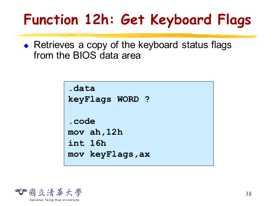
Function 12h: Get Keyboard Flags
Retrieves a copy of the keyboard status flags from the BIOS data area .data keyFlags WORD ? .code mov ah,12h int 16h mov keyFlags,ax

39
Overview How Does a PC Boot?
40
Boot Process Step 0: CPU Reset Step 1: Power-on self test (POST)
Blank memory, except ROM Start running from address FFFF0 (only 16 bytes left!) Step 1: Power-on self test (POST) Step 2: ROM BIOS startup program searches for and loads an OS Step 3: OS configures the system and completes its own loading Step 4: User executes applications software
 Step 1: Power-on self test (POST) Step 2: ROM BIOS startup program searches for and loads an OS. Step 3: OS configures the system and completes its own loading. Step 4: User executes applications software.")
41
Step 1: POST & BIOS Boot A built-in diagnostic program that checks the hardware to ensure that everything is present and functioning properly, before the BIOS begins the actual boot. It then continues with additional tests, e.g., memory test, as boot process is proceeding. The ROM BIOS startup program surveys hardware resources and needs, and assigns system resources to meet those needs

42
POST

43
Step 2: BIOS Finds & Loads OS
Most often the OS is loaded from logical drive C on the hard drive Configuration information on CMOS chip tells startup BIOS where to look for the OS BIOS turns to that device, reads the beginning files of the OS, copies them into memory, then turns control over to the OS Master Boot Record (MBR) loaded.
 loaded.")
44
BIOS Finds & Loads OS

45
Step 3: OS Completes Boot
The OS checks some of the same things that startup BIOS checked (e.g., available memory and whether memory is reliable) The OS loads software to control the mouse, a CD-ROM, a scanner, and other peripheral devices (generally have device drivers)
 The OS loads software to control the mouse, a CD-ROM, a scanner, and other peripheral devices (generally have device drivers)")
46
Boot Process

47
Step 4: User Executes Applications Software
The OS finds the applications software (on a secondary storage device), copies software into memory, and turns control over to it User commands the applications software, which makes requests to the OS, which uses the system resources, system BIOS, and device drivers to interface with and control the hardware
, copies software into memory, and turns control over to it. User commands the applications software, which makes requests to the OS, which uses the system resources, system BIOS, and device drivers to interface with and control the hardware.")
48
Summary MS-DOS applications 16-bit segments, segmented addressing, running in real-address mode Software interrupts processed by interrupt handlers INT (call to interrupt procedure) instruction pushes flags & return address on the stack uses interrupt vector table to find handler BIOS Services (INT 10h, INT 16h, INT 17h, ...) MS-DOS Services (INT 21h) PC Guide – BIOS System Boot
 instruction. pushes flags & return address on the stack. uses interrupt vector table to find handler. BIOS Services (INT 10h, INT 16h, INT 17h, ...) MS-DOS Services (INT 21h) PC Guide – BIOS System Boot")
Similar presentations


>")

 Pearson Education, 2006-2007. All rights reserved. You may modify and.>")


>")


 Procedures Procedure Parameters Software Interrupts MS-DOS.>")

 Pearson Education, 2002. All rights reserved. You may.>")
 Pearson Education, 2006-2007. All rights reserved. You may modify.>")


. I/O Devices Input/output (I/O) devices provide the means to interact with the “outside world”. An I/O device.>")

 Pearson Education, 2006-2007. All rights reserved. You.>")