Download presentation
Presentation is loading. Please wait.

1
Sequencing and Control Mano and Kime Sections 8-1 – 8-7

2
Sequencing and Control Algorithmic State Machines Binary Multiplier Hardwired Control Binary Multiplier – VHDL Microprogrammed Control

3
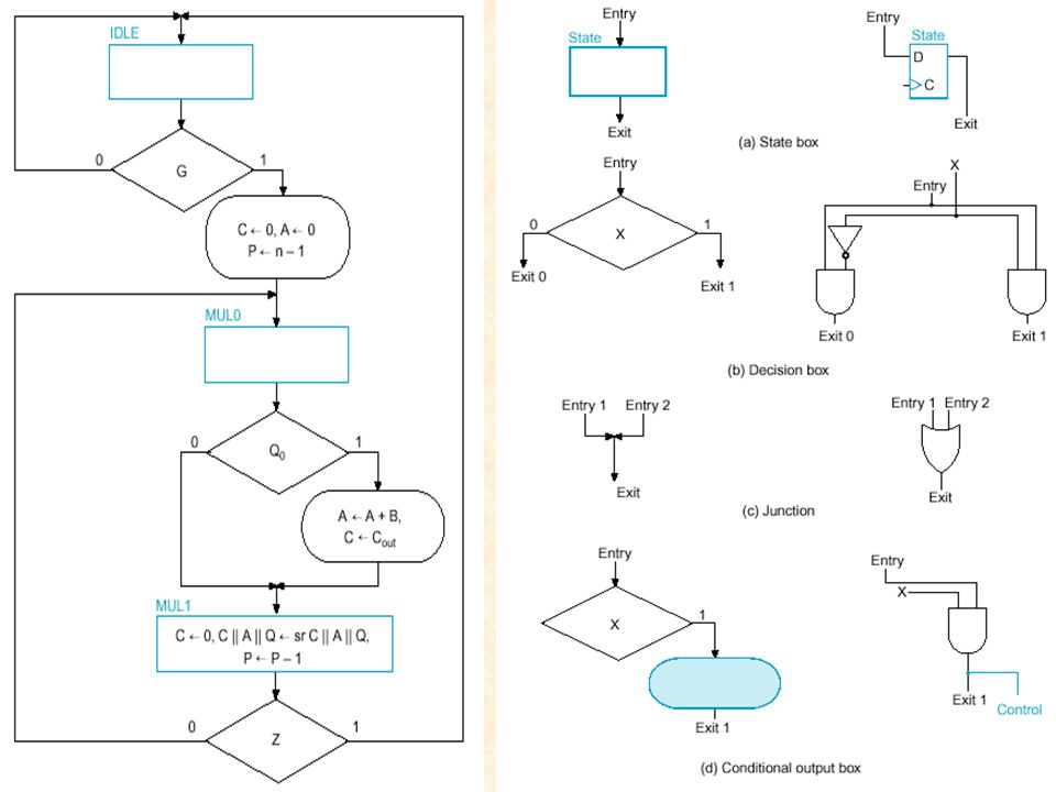
Algorithmic State Machine

4
ASM Block Timing

5
Sequencing and Control Algorithmic State Machines Binary Multiplier Hardwired Control Binary Multiplier – VHDL Microprogrammed Control

6
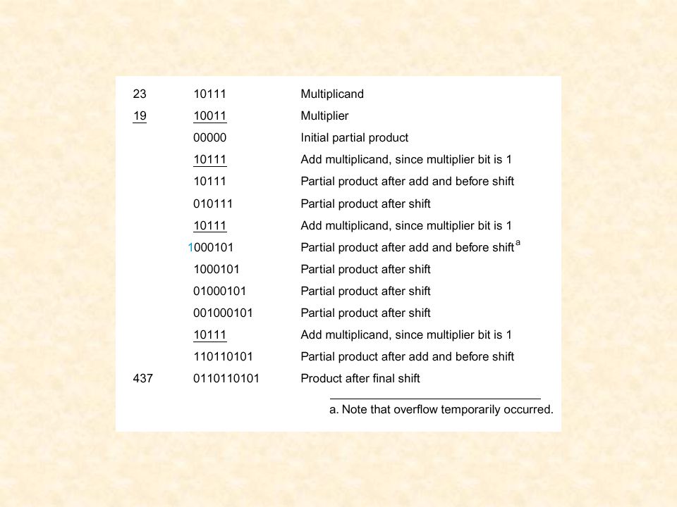
An Algorithmic Binary Multiplier Either adding the multiplier or 0000

8
Shifting partial product right is the same as shifting the multiplier to the left

10
Initialize the multiplier If GO Then

11
Begin in state MUL0

12
If the right-most bit of the multiplier in the Q shift register is 0 then goto state MUL1

13
Otherwise, if the right-most bit of the multiplier is 1 then add the partial product (A) to the multiplicand (B) and store it in A. Prepare to shift in C.

14
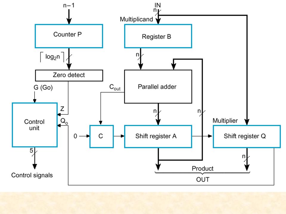
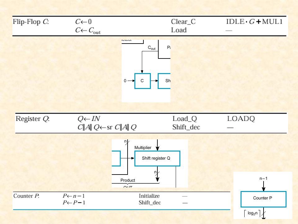
Shift a 0 into C, shift right C || A || Q into C || A || Q Decrement P C || A || Q denotes a composite register.

15
If Z = 1 then we have gone through the state machine n -1 times and we are finished

16
Otherwise, if Z = 0 we continue back to state MUL0.

17
Register A contains the four most significant bits of the product and Register Q contains the four least significant bits of the product when we are finished. Note that n-bits x n-bits <= 2n bits

18
Sequencing and Control Algorithmic State Machines Binary Multiplier Hardwired Control Binary Multiplier – VHDL Microprogrammed Control

19
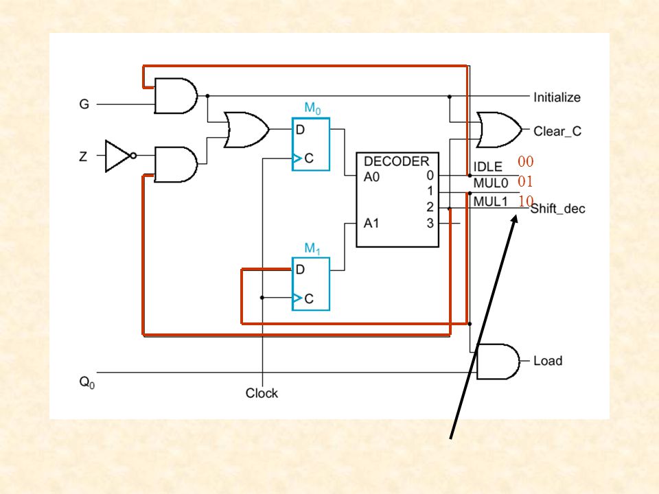
Let’s take a closer look at the control unit

22
Sequencing State Machine

23
Decoder outputs based off of the present state --The decoder plays role in controlling the next state

24
00 01 10
25
ASM chart transformation rules with one flip-flop per state Notice two flip flops for the two states, MUL0 and MUL1

27
Decision Box Idle Junction (from Z and G) Idle State junction State MUL0 State MUL1 Z Decision Box
 Idle State junction State MUL0 State MUL1 Z Decision Box")
28
Sequencing and Control Algorithmic State Machines Binary Multiplier Hardwired Control Binary Multiplier – VHDL Microprogrammed Control

29
VHDL -- Binary Multiplier with n=4; VHDL Description library ieee; use ieee.std_logic_1164.all; use ieee.std_logic_unsigned.all; entity binary_multiplier is port(CLK, RESET, G, LOADB, LOADQ: in std_logic; MULT_IN: in std_logic_vector(3 downto 0); MULT_OUT: out std_logic_vector(7 downto 0)); end binary_multiplier;
; MULT_OUT: out std_logic_vector(7 downto 0)); end binary_multiplier;")
30
architecture behavior_4 of binary_multiplier is type state_type is (IDLE, MUL0, MUL1); signal state, next_state : state_type; signal A, B, Q: std_logic_vector(3 downto 0); signal P : std_logic_vector(1 downto 0); signal C, Z: std_logic; begin Z <= (P1) NOR P(0); MULT_OUT <= A & Q; state_register: process (CLK, RESET) begin if (RESET = ‘1’) then state <= IDLE; elsif (CLK’event and CLK = ‘1’) then state <= next_state; end if; end process; State Machine
; signal state, next_state : state_type; signal A, B, Q: std_logic_vector(3 downto 0); signal P : std_logic_vector(1 downto 0); signal C, Z: std_logic; begin Z <= (P1) NOR P(0); MULT_OUT <= A & Q; state_register: process (CLK, RESET) begin if (RESET = ‘1’) then state <= IDLE; elsif (CLK’event and CLK = ‘1’) then state <= next_state; end if; end process; State Machine")
31
next_state_func: process (G, Z, state) begin case state is when IDLE => if G = ‘1’ then next_state <= MUL0; else next_state <= IDLE; end if; when MUL0 => next_state <= MUL1; when MUL1 => if Z = ‘1’ then next_state <= IDLE; else next_state <= MUL0; end if; end case; end process; Next State
 begin case state is when IDLE => if G = ‘1’ then next_state <= MUL0; else next_state <= IDLE; end if; when MUL0 => next_state <= MUL1; when MUL1 => if Z = ‘1’ then next_state <= IDLE; else next_state <= MUL0; end if; end case; end process; Next State")
32
datapath_func: process (CLK) variable CA: std_logic_vector(4 downto 0); begin if (CLK’event and CLK = ‘1’) then if LOADB = ‘1’ then B <= MULT_IN; end if; if LOADQ = ‘1’ then Q <= MULT_IN; end if; case state is when IDLE => if G = ‘1’ then C <= ‘0’; A <= “0000”; P <= “11”; end if; when MUL0 => if Q(0) = ‘1’ then CA := (‘0’ & A) + (‘0’ & B); else CA := C & A; end if; C <= CA(4); A <= CA(3 downto 0); when MUL1 => C <= ‘0’; A <= C & A(3 downto 1); Q <= A(0) & Q(3 downto 1); P <= P - “01”; end case; end if; end process; end behavior_4; DATAPATH
 variable CA: std_logic_vector(4 downto 0); begin if (CLK’event and CLK = ‘1’) then if LOADB = ‘1’ then B <= MULT_IN; end if; if LOADQ = ‘1’ then Q <= MULT_IN; end if; case state is when IDLE => if G = ‘1’ then C <= ‘0’; A <= 0000 ; P <= 11 ; end if; when MUL0 => if Q(0) = ‘1’ then CA := (‘0’ & A) + (‘0’ & B); else CA := C & A; end if; C <= CA(4); A <= CA(3 downto 0); when MUL1 => C <= ‘0’; A <= C & A(3 downto 1); Q <= A(0) & Q(3 downto 1); P <= P - 01 ; end case; end if; end process; end behavior_4; DATAPATH")
33
Sequencing and Control Algorithmic State Machines Binary Multiplier Hardwired Control Binary Multiplier – VHDL Microprogrammed Control

34
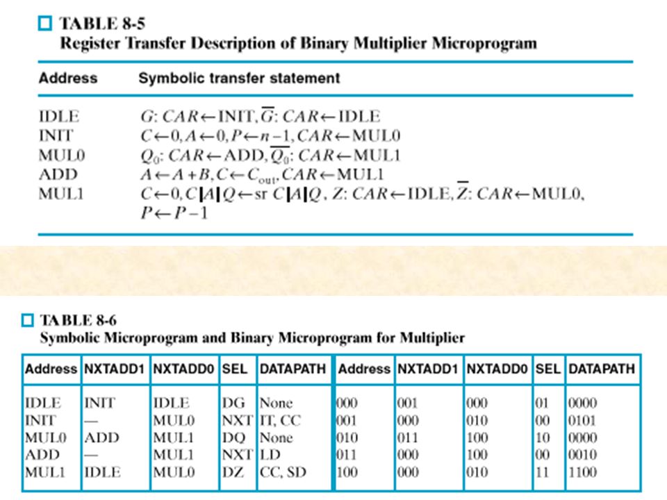
In general… Microprogrammed Control Unit Organization Acts like a control output lookup table Addresses lookup table

35
ASM Chart for microprogrammed Control Unit Basic ASM Chart from initial design Note 5 states

36
What do we store in our lookup ROM? A Micro-instruction Control Word Next state (1 or 5)
")
37
Control Signals With this in mind, we need to design the control words...

38
Use two next_addresses

39
Microprogrammed Control Unit for Multiplier

Similar presentations

 part 1. ASM2 Algorithmic State Machine (ASM) Our design methodologies do not scale well to real-world problems.>")


>")
 then for i in 0 to 2 loop s(i) >")


 VHDL –2 x 1 MUX –4 x 1 MUX –An Adder –Binary-to-BCD Converter –A Register.>")

>")

 Charts>")
 Charts,>")

 qs(2) qs(1) qs(0) if rising_edge(CLK) then for i in 0 to 2 loop s(i) := s(i+1);>")

