Download presentation
Presentation is loading. Please wait.

1
Propagation of HI Beams in Chamber Metal Vapor Atmosphere C. Olson, Sandia National Laboratories D. Welch, D. Rose, B. Oliver, T. Genoni, and R. Clark, Mission Research Corporation S. Yu, Lawrence Berkeley National Laboratories ARIES Electronic Project Meeting 10-24-01

2
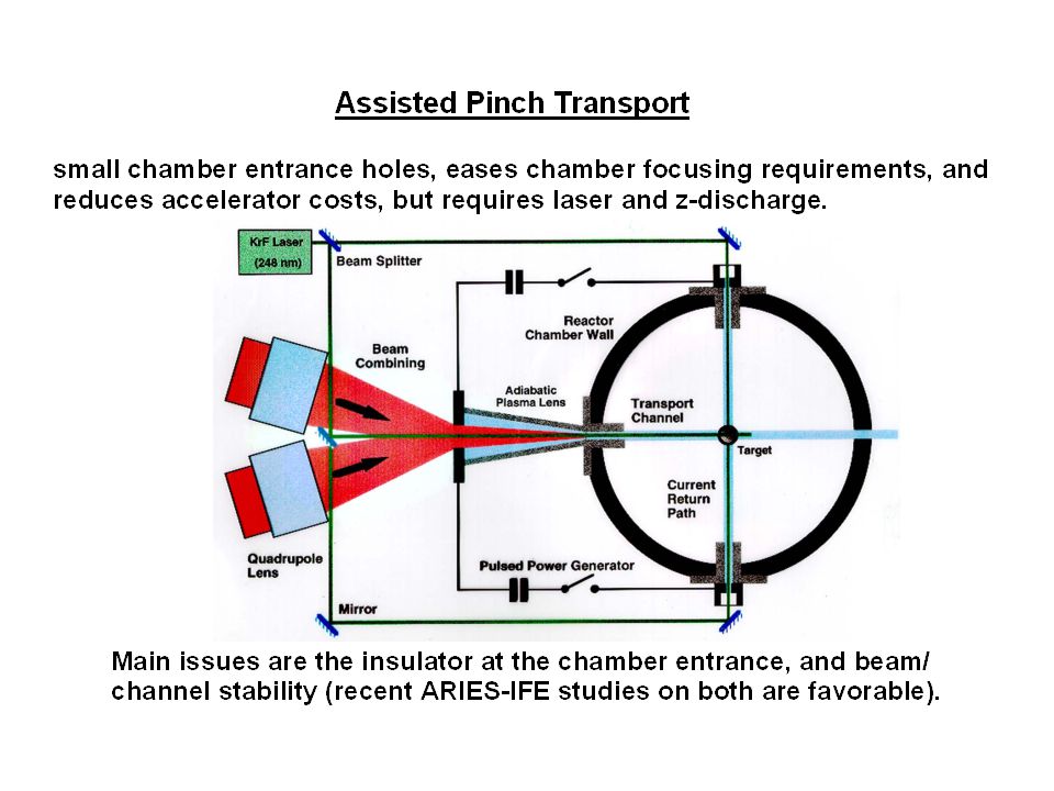
Outline ARIES - HIF propagation modes vs. chamber wall type Wetted-wall power plant studies (HIBALL HI, OSIRIS-HIB, PROMETHEUS-H) Neutralized ballistic transport (concept/issues, LSP examples) Assisted pinch transport (concept/issues, LSP examples) Self-pinched transport (concept/issues, LSP examples) ARIES - HIF propagation modes vs. chamber wall types
 Neutralized ballistic transport (concept/issues, LSP examples) Assisted pinch transport (concept/issues, LSP examples) Self-pinched transport (concept/issues, LSP examples) ARIES - HIF propagation modes vs. chamber wall types.")
4
Wetted-Wall HIF Power Plant Studies HIBALL HI Reactor Study (1981): First wall: HT-9 ferritic steel INPORT tubes: SiC with PbLi flow Pressure: 10 -5 Torr Pb Ballistic transport (in vacuum) OSIRIS-HIB Design (1992): First wall: three-layer carbon cloth blanket Flibe coolant bleeding through cloth Pressure: 2x10 -4 Torr Neutralized ballistic transport with co-moving electrons PROMETHEUS-H Reactor Design Study (1992): First wall: SiC porous thin film of liquid Pb Pressure: 100 mTorr Self-pinched transport
: First wall: HT-9 ferritic steel INPORT tubes: SiC with PbLi flow Pressure: Torr Pb Ballistic transport (in vacuum) OSIRIS-HIB Design (1992): First wall: three-layer carbon cloth blanket Flibe coolant bleeding through cloth Pressure: 2x10 -4 Torr Neutralized ballistic transport with co-moving electrons PROMETHEUS-H Reactor Design Study (1992): First wall: SiC porous thin film of liquid Pb Pressure: 100 mTorr Self-pinched transport")
5
Neutralized Ballistic Transport Neutralization by: preformed plasma, gas, photoionization Key Issues: handling beams stripped to Z 1, transport lengths beyond 3 meters Plasma Plug (externally injected plasma) Low pressure chamber (~ 10 -3 Torr). Final focus magnet Target Volume plasma (from photoionization of hot target) Converging ion beam Chamber Wall
 Converging ion beam Chamber Wall.")
6
Driver Scale Beam Simulations: Vacuum Photo Plasma C L Beam Conducting Boundaries CL emission Beam Focal Point 300 cm 3.0 cm Pb +1 ion beam GeV, = 0.2 30 mm-mrad emittance I b = 4 kA K = (1.5x10 -4 )Z need K net (3x10 -6 )/Z With and without Photo-ionized plasma (peak 5x10 13 cm -3 ) W. Sharp

7
Photo plasma crucial to good spot Stripped ions deflected by un-neutralized charge at beam edge Plasma provides > 99% neutralization, focus at 265 cm No PlasmaPlasma Pb +2 Pb +3 Pb +4 Pb +5 Pb +2 Pb +3 Pb +4 Pb +5 Log Pb density mean charge state

8
Plasma simulation spot slightly better than ballistic case Residual net current results in premature but tight focus (pinching near target) Net Current (A) within r 14 ns 28 ns 42 ns 52 ns 90% of beam within 3 mm
 Net Current (A) within r 14 ns 28 ns 42 ns 52 ns 90% of beam within 3 mm")
10
IPROP is used to model beam/plasma interaction with initial discharge conditions IPROP is a quasi 3D EM hybrid code 2 T fluid model for the plasma, PIC beam ions Ohm’s Law, J e = ( p e /n e -v i m + E + v B) Spitzer, e-neutral resistivity Ionization X-section falls as 1/Z 2 Moliere scattering, Bethe slowing down 50-kA discharge 5-Torr, 3 eV ambient Xe 0.5 torr reduced density within discharge Initial Discharge Conditions
 Spitzer, e-neutral resistivity Ionization X-section falls as 1/Z 2 Moliere scattering, Bethe slowing down 50-kA discharge 5-Torr, 3 eV ambient Xe 0.5 torr reduced density within discharge Initial Discharge Conditions")
11
87% energy transport, 3.5-mm RMS radius calculated for APT 10 m ballistic transport Pb +72 15 cm 4-GeV, 6 MA Pb +72 ions, 1-mrad divergence 10-m ballistic transport to discharge Calculated m = 5 s limits net current growth to 30 kA over 8-ns pulse halo grows from self-field interaction Discharge radius halo B fields 80 ns

12
3D IPROP simulation shows negligible hose growth IPROP with m=0,1 Fourier modes Constant, specified radial profile In both cases, offsets remain < 1 mm Low m simulation shows much less growth than theory –result of betatron detuning from 300-kA net current? m =80ns m =5 s

13
Self-Pinched Transport Target Chamber Wall 3-cm radius beams are focused outside of chamber down to ~3-mm radius. Many-beam SPT chamber mode (N > 10) Small-radius openings in chamber wall Final Focus Section I b = 4 kA, highly stripped Issues: beam front erosion, aiming/tracking, multiple beam effects, and beam/plasma stability (ARIES-IFE studies are continuing)
 Small-radius openings in chamber wall Final Focus Section I b = 4 kA, highly stripped Issues: beam front erosion, aiming/tracking, multiple beam effects, and beam/plasma stability (ARIES-IFE studies are continuing).")
14
Self-pinched transport is predicted to occur at an intermediate gas pressure Maximum pinch force occurs when beam-impact ionizes a plasma density roughly that of the beam on time-scale of beam density rise time, L/v b Optimized for normalized trumpet length: R =L n g /4Z =1 * Trumpet shape and non- local secondary ionization supply neutralization without v e = v b * D.R. Welch and C.L. Olson, Fus. Eng. and Des. 32-33, 477 (1996). - + Beam - + E E B B lab frame c Electron orbits are mainly ExB L
. - + Beam - + E E B B lab frame c Electron orbits are mainly ExB L.")
15
LSP calculates maximum I net near normalized trumpet length of unity LSP simulations of 10-kA, 4-GeV Pb + beam Beam trumpet 7 mm to 0.35 mm in 2 ns or 12 cm

16
1-m propagation demonstrates pinched equilibrium for R = 0.14 Transient evaporation of current due to mismatch 10 ns 20 ns Tightly pinched beam core with 6-kA net current 65-kA, 4-GeV Pb +65 beam 8-ns pulse = 0.5 ns, 7-3.5 mm radius 50-mTorr Xe gas fill Only 61% transport within 6 mm radius after 1-m Tolerable ss erosion rate 10 -3

17
Transport Conclusions No show stoppers discovered for any of the transport schemes State of theory for NBT is the most mature - plasma via photo-ionization greatly improves transport for 3 m length APT results are sensitive to gas conductivity - present modeling calculates decay length sufficient to suppress deleterious self-field effects. SPT calculations have identified propagation window in 10-150 mTorr Xe - pinched equilibrium simulated. Efficiency of energy transport and 3D stability issues need to be addressed.

Similar presentations


 Thermal Hydraulics Laboratory Department of Nuclear Engineering.>")


