Download presentation
Presentation is loading. Please wait.

2
Nearfield Spherical Microphone Arrays for speech enhancement and dereverberation Etan Fisher Supervisor: Dr. Boaz Rafaely

3
Microphone Arrays Spatial sound acquisition Sound enhancement Applications: reverberation parameter estimation dereverberation video conferencing

4
Spheres The sphere as a symmetrical, natural entity. Spherical symmetry Facilitates direct sound field analysis: Spherical Fourier transform Spherical harmonics Photo by Aaron Logan

5
Nearfield Spherical Microphone Array Generally, the farfield, plane wave assumption is made (Rafaely, Meyer & Elko). In the nearfield, the spherical wave-front must be accounted for. Examples: Close-talk microphone Nearfield music recording Multiple speaker / video conferencing

6
Sound Pressure - Spherical Wave Sound pressure on sphere r due to point source r p (spherical wave): Spherical harmonics: From the solution to the wave equation (spherical coordinates):
: Spherical harmonics: From the solution to the wave equation (spherical coordinates):")
7
Sound Pressure - Spherical Wave Sound pressure on sphere r due to point source r p : Spherical harmonics: The spherical harmonics are orthogonal and complete. From the solution to the wave equation (spherical coordinates):
:.")
8
Sound Pressure - Spherical Wave Sound pressure on sphere r due to point source r p : is the spherical Hankel function. is the modal frequency function (Bessel):
:.")
9
Spherical Spectrum Functions

11
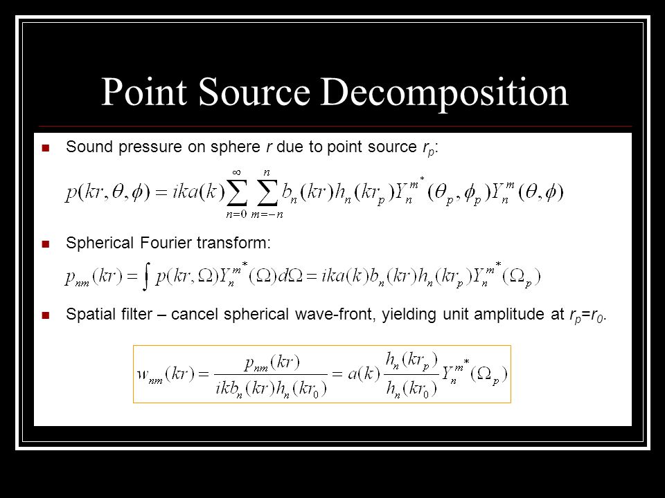
Point Source Decomposition Sound pressure on sphere r due to point source r p : Spherical Fourier transform: Spatial filter – cancel spherical wave-front, yielding unit amplitude at r p =r 0.

12
Point Source Decomposition Amplitude density: Using the identity: where Θ is the angle between Ω and Ω p,

13
Nearfield Criteria NOrder of array kWave number r A Array radius r s Source distance

14
N = 4; r A (array) = 0.1m; k = k max k max = N/r A = 40 k max = 2πf max /343 f max = 2184 Hz r 0 – Desired source location r p – Interference location Radial Attenuation
 = 0.1m; k = k max k max = N/r A = 40 k max = 2πf max /343 f max = 2184 Hz r 0 – Desired source location r p – Interference location Radial Attenuation")
15
N = 4; r A (array) = 0.1m; k = k max /4 k max = N/r A = 40 k max = 2πf max /343 f max = 2184 Hz r 0 – Desired source location r p – Interference location Radial Attenuation
 = 0.1m; k = k max /4 k max = N/r A = 40 k max = 2πf max /343 f max = 2184 Hz r 0 – Desired source location r p – Interference location Radial Attenuation")
16
N = 4; r A (array) = 0.1m; k = k max /10 k max = N/r A = 40 k max = 2πf max /343 f max = 2184 Hz r 0 – Desired source location r p – Interference location Radial Attenuation
 = 0.1m; k = k max /10 k max = N/r A = 40 k max = 2πf max /343 f max = 2184 Hz r 0 – Desired source location r p – Interference location Radial Attenuation")
17
N = 2; r A (array) = 0.05 m; k = k max k max = N/r A = 40 k max = 2πf max /343 f max = 2184 Hz r 0 – Desired source location r p – Interference location Radial Attenuation – “ Close Talk ”
 = 0.05 m; k = k max k max = N/r A = 40 k max = 2πf max /343 f max = 2184 Hz r 0 – Desired source location r p – Interference location Radial Attenuation – Close Talk")
18
N = 2; r A (array) = 0.05 m; k = k max /4 k max = N/r A = 40 k max = 2πf max /343 f max = 2184 Hz r 0 – Desired source location r p – Interference location Radial Attenuation – “ Close Talk ”
 = 0.05 m; k = k max /4 k max = N/r A = 40 k max = 2πf max /343 f max = 2184 Hz r 0 – Desired source location r p – Interference location Radial Attenuation – Close Talk")
19
N = 12; r A (array) = 0.3 m; k = k max /4 k max = N/r A = 40 k max = 2πf max /343 f max = 2184 Hz r 0 – Desired source location r p – Interference location Radial Attenuation – Large Array
 = 0.3 m; k = k max /4 k max = N/r A = 40 k max = 2πf max /343 f max = 2184 Hz r 0 – Desired source location r p – Interference location Radial Attenuation – Large Array")
20
N = 4; r A (array) = 0.1m; k = k max k max = N/r A = 40 k max = 2πf max /343 f max = 2184 Hz The natural radial attenuation has been cancelled by multiplying the array output by the distance. Normalized Beampattern

21
N = 4; r A (array) = 0.1m; k = k max /4 k max = N/r A = 40 k max = 2πf max /343 f max = 2184 Hz The natural radial attenuation has been cancelled by multiplying the array output by the distance. Normalized Beampattern

22
N = 4; r A (array) = 0.1m; k = k max /10 k max = N/r A = 40 k max = 2πf max /343 f max = 2184 Hz The natural radial attenuation has been cancelled by multiplying the array output by the distance. Normalized Beampattern

23
Directional Impulse Response Amplitude density: Impulse response at direction Ω 0 : where is the ordinary inverse Fourier transform.

24
Speech Dereverberation Room IR Directional IR {4 X 3 X 2} N = 4 r = 0.1 m r 0 = 0.2 m “Dry” “Rev.” “Derev.”

25
Music Dereverberation Room IR Directional IR { 8 X 6 X 3 } N = 4 r = 0.1 m r 0 = 1.9 m “Dry” “Rev.” “Derev.”

26
Conclusions Spherical wave pressure on a spherical microphone array in spherical coordinates. Point source decomposition achieves radial attenuation as well as angular attenuation. Directional impulse response (IR) vs. room IR. Speech and music dereverberation. Further work: Develop optimal beamformer Experimental study of array
 vs. room IR. Speech and music dereverberation. Further work: Develop optimal beamformer Experimental study of array.")
Similar presentations


 ● Standard Definitions ● Computing the DFT and FFT ● Sine and cosine wave multiplication.>")
 create images in the spatial domain Pixels represent features (intensity,>")

 filters (we have not yet seen why) Analysis tool for LSI filters: Fourier transform.>")
, the Fourier spectrum is: FOURIER SPECTRUM: Time Domain (TD)-Frequency-Domain (FD) and vice- versa Dr. Sinan Akkar Strong.>")


