Download presentation
Presentation is loading. Please wait.

1
Modeling the imaging system Why? If a customer gives you specification of what they wish to see, in what environment the system should perform, you as the designer should be able to specify the space of observables, that is the observable reachable set. We can specify the range of parameters in which we can guarantee a certain performance of the system.

2
What are the components of an imaging system? Optics: Field of view (FOV) Focal length f Center of optical axes Spherical aberration which leads to blur circle,where b is the blur, d is the diameter of the lens and z’ is the imaged distance form the lens, while z is the real distance that we wish to have in focus
 Focal length f Center of optical axes Spherical aberration which leads to blur circle,where b is the blur, d is the diameter of the lens and z’ is the imaged distance form the lens, while z is the real distance that we wish to have in focus.")
3
The effects of light on our imaging system Denote radial flux measured in Watts Then the amount of energy on a patch A Will be Irradiance E The Radiant Intensity I will be Finally Radiance L is the power per unit projection to solid angle

4
Light Sources We consider point source (isotropic) and area source (hemispheric) If point but isotropic source, how much light is getting to the surface patch? The radiant intensity over a full sphere is

5
Point isotropic source The amount of flux projected on solid angle will be proportional to intensity over the full sphere and the solid angle Hence the irradiance on the patch A will be

6
Reflectance If the source is hemispherical then the Irradiance E will be proportional to radiance multiplied by PI. Reflectance f is defined as the ratio between the amount of light that gets reflected (Radiance L) and the amount of light collected on the surface patch (Irradiance E). In this case the surface becomes the light source! I stands for incident and r for reflected
 and the amount of light collected on the surface patch (Irradiance E). In this case the surface becomes the light source. I stands for incident and r for reflected.")
7
Diffuse Reflectance Stands for the assumption that the light from the surface appears equally bright from all viewing directions, hence the radiance L is constant. We can write:where B stands for Body, s stands for surface

8
Lambertian reflection Same assumption as in the ideal diffuse reflection but the surface absorbs some light

9
Know your sensor:Sensor Errors These errors are called intrinsic. Any undesired feature causing discrepancies in digital image is considered noise. Systematic noise (errors) effect the ACCURACY of vision algorithms. Random errors primarily effect the PRECISION, i.e the variability in the results due to random noise in the digital images. In ordre to establish the accuracy, the results must be compared with ground truth models which are difficult to obtain.
 effect the ACCURACY of vision algorithms. Random errors primarily effect the PRECISION, i.e the variability in the results due to random noise in the digital images. In ordre to establish the accuracy, the results must be compared with ground truth models which are difficult to obtain..")
10
Precision A complete characterization of the precision consists of a probability distribution for output noise. It is very difficult to get this since usually there are too many factors influencing the results. A methodology for performance evaluation should include characterization not only of the errors depending on the environmental conditions (extrinsic errors) but also on sensor characteristics.
 but also on sensor characteristics..")
11
The Video Sensor The Video sensor consists of a lens, a CCD camera and a frame-grabber. The image is formed on the CCD array of identical sensing elements (sells) and then transferred by the frame-grabber in a linear order (line by line) to the computer memory. The geometric and radiometric uncertainties and discrepancies in the digital image are due to the optics, the CCD camera and the joint operation of the camera, the frame-grabber and other electronic components.
 and then transferred by the frame-grabber in a linear order (line by line) to the computer memory. The geometric and radiometric uncertainties and discrepancies in the digital image are due to the optics, the CCD camera and the joint operation of the camera, the frame-grabber and other electronic components..")
12
Camera related noise The total random noise of the CCD has three major components: Photon (shot) noise Read noise Fixed pattern noise The source of the photon noise is external, due to fluctuations of the photon flux and is always present in the data.
 noise Read noise Fixed pattern noise The source of the photon noise is external, due to fluctuations of the photon flux and is always present in the data.")
13
Camera related noise The read noise is related to the physics of the camera and the measurement process (the background noise and the output amplifier noise). Noticeable components of the background noise are the dark current (thermally generated charges) and the internal luminescence. Dark current doubles with increase of temperature by 8 degrees but is also due to irregularities in the crystal structure which contributes to a fixed pattern noise. There is also non uniformity in photo response in individual photocells which is observed in flat fields
 and the internal luminescence. Dark current doubles with increase of temperature by 8 degrees but is also due to irregularities in the crystal structure which contributes to a fixed pattern noise. There is also non uniformity in photo response in individual photocells which is observed in flat fields.")
14
Radiometric correction Given even, absolutely the same scene and illumination, physically different sensors see differently. Radiometric correction is also called flat fielding. Corrected image is achieved with zero offset and constant gain, we subtract from the original image the offset observed in averaged dark image, and scale the resulting image inversely proportional to the photo response observed in average flat field.

15
Intrinsic parameters-Geometric Image formation

16
Intrinsic parameters (contd.) Skew pixels Overall intrinsic parameter matrix
 Skew pixels Overall intrinsic parameter matrix")
17
CAMERA PARAMETERS – Radial Distortion Nonlinear transformation along the radial direction Distortion correction: make lines straight

18
Frame-grabber related noise Geometric discrepancies due to the digitization in the frame-grabber are Aliasing Line jitter Systematic fall-ff of the intensity in a line. An effect of radiometric distortion due to interlacing is the shift in gray level between odd and even fields in a frame.

19
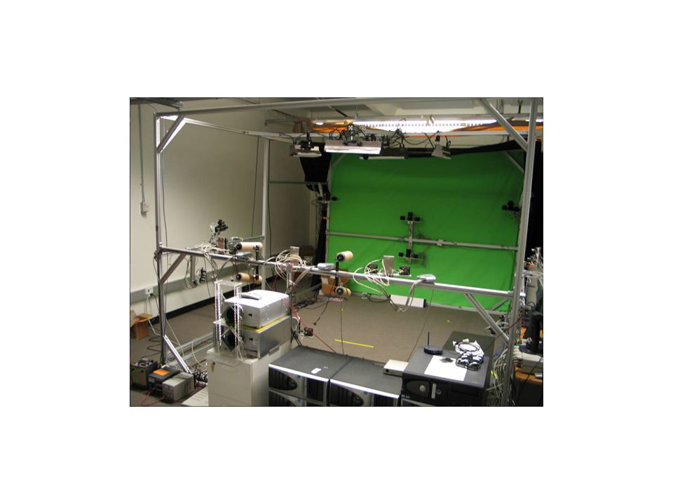
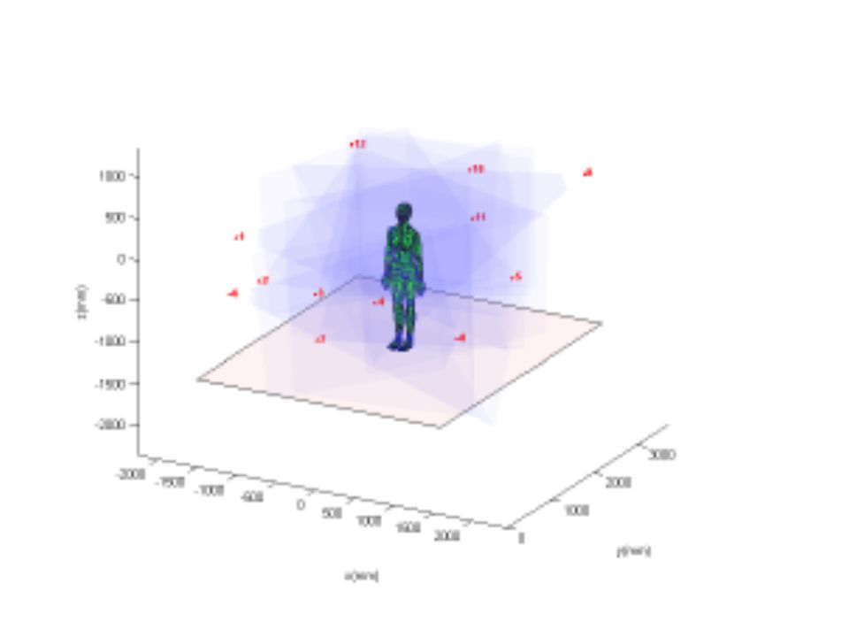
Example of Multi-camera setup The calibration in the multi-camera setup is more important than otherwise, because the cameras as imaging system must be normalized and coordinated.

22
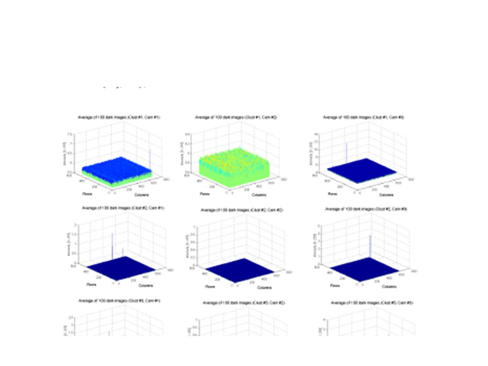
Dark Image analysis The Method: We took 3 black and white cameras and closed their lenses in the dark room. For each camera we recorded 100 dark images with delay of 20ms between two consecutive images. Stability of background noise was examined by capturing 100 dark images over 100 second. For each set of dark images average per pixel intensity was calculated and max and min of pixel values was determined

23
Example of modeling dark noise

24
One “bad” camera

25
Table of results of the mean intensity of 1000 dark images

27
Conclusion on dark image noise Is that by and large this effect and the fixed patter noise is negligible for reconstruction purposes. What remains to be examined is the flat field,that is the response of the sensor to uniform light illumination.

28
Radial distortion Will assume compensated (Tsai ’86) see Intel OpenCV in lab assignment
 see Intel OpenCV in lab assignment")
31
Conclusion What is the observable reachable set? It is a multidimensional space delineated by the range limits of all the Image acquisition parameters plus the assumptions that one makes about the illumination system, the environment and the task/context. What is the benefit? One can make performance guarantees within the bounds.

32
Summary of parameters Optics: FOV, focal length diameter of lens; CCD: light /spectral sensitivity range The dark current, the saturation to light level, The homogeneity of the array of light sensitive cells; Assumptions about illumination source (Intensity ), its extend (point source vs hemispherical source), the distance from the scene and if possible the angle of incident light;
, its extend (point source vs hemispherical source), the distance from the scene and if possible the angle of incident light;")
33
Summary of parameters, cont. Assumptions about the scene materials (lambertian, metallic, plastic, surface texture smooth vs. rough,and so on) Geometric intrinsic parameters of the camera, scale of pixels, center of the imaging device and radial distortion; Spatial temporal and Signal resolution. This includes the speed of Analog to Digital conversion; Finally, if the task is to have a system in varied atmospheric conditions, such as fog, rain and night, different spectral bands will be required
 Geometric intrinsic parameters of the camera, scale of pixels, center of the imaging device and radial distortion; Spatial temporal and Signal resolution. This includes the speed of Analog to Digital conversion; Finally, if the task is to have a system in varied atmospheric conditions, such as fog, rain and night, different spectral bands will be required.")
34
How to obtain these parameters? Some come from the manufacturer and it is the designer who selects them. The other have to be measured during the setup time, calibration time. The parameters on the environment, can only be estimated but the range can be given.

Similar presentations


 General strategy: view calibration.>")


 UCLA Vision Lab 1 Homogeneous representation Points Vectors Transformation representation.>")

. What is the relation between pixel.>")


>")
