Download presentation
Presentation is loading. Please wait.

1
Principle of Screw and Plate Fixation & Mechanical Behavior of Implant Materials

2
Roles of Implants Add stability Replace damaged or diseased part
Fracture fixation A plate used after osteotomy Replace damaged or diseased part Total joint replacement Healing stimulants

3
Advantages of Internal Fixation
No casts Prevent skin pressure and fracture blisters No scars No complications of bed rest Important for the elderly Early motion Avoid stiffness Enhance fracture healing Prevent muscle atrophy

4
Principles of Fixation
Rigid fixation Stress distribution Fracture stability Compression Stability Primary healing Membranous bone repair

5
Biomechanics of Dynamic Compression Plate (DCP)
Designed to compress the fracture Offset screws exert force on specially designed holes in plate Force between screw and plate moves bone until screw sits properly Compressive forces are transmitted across the fracture Beginning End Result ttb.eng.wayne.edu/ ~grimm/ME518/L19F3.html

6
DCP (Cont’d) Alternate embodiment:
External compression screw control Additional pictures of internal plate

7
Plate Placement Lateral cortex Flexural rigidity
E * I Depends on direction of loading Area moment of inertia

8
Plate and oblique fracture
A: For ONLY torsional loads: 45° to long axis B: For ONLY bending loads: Parallel to long axis Realistically: loads in both directions will be applied: Divide angle between long axis and 45° B

9
Dynamic Hip & Condular Screw Indications (DHS)
Fractures of the proximal femur Intertrochanteric fractures Subtrochanteric fractures Basilar neck fractures Stable fractures Unstable fractures in which a stable medial buttress can be reconstructed Provide controlled collapse and compression of fracture fragments

10
Sliding Compression Screw Devices
Screw in center of femoral head (proximal fragment) Slides through barrel attached to plate See yellow arrow Essential to obtain max hold capacity in head of femur Plate is attached to bone (distal fragment) by screws Screw threads designed to allow optimum fracture compression and hold
 Slides through barrel attached to plate. See yellow arrow. Essential to obtain max hold capacity in head of femur. Plate is attached to bone (distal fragment) by screws. Screw threads designed to allow optimum fracture compression and hold.")
11
Sliding Screw Plate Angle
For anatomic reduction Less force working across sliding axis than higher angle plates Prevents impaction Used effectively in stable fractures Controlled collapse is not important

12
Sliding Screw Plate Angle
For unstable fractures Mechanically, it is desirable to place sliding device at as high angle as clinically possible while still maintaining placement of device in center of head Technically surgeon cannot place sliding device at high angle in small hip or in hip with varus deformity

13
DHS Technique Incisional line
Red = conventional Green = minimal access Procedure is monitored by x-ray image intensifier

14
DHS Targeting Device Aligns guide pin Under the vastus lateralis
Wedged in upper part Between vastus and femoral shaft

15
DHS Guide Pin Guide pin is inserted Centered in the femoral neck

16
DHS Axial Screw Axial screw is inserted with an extension
Extension to guide the barrel of plate Slot along screw fits a longitudinal ridge inside barrel prevents rotation, allows axial compression only

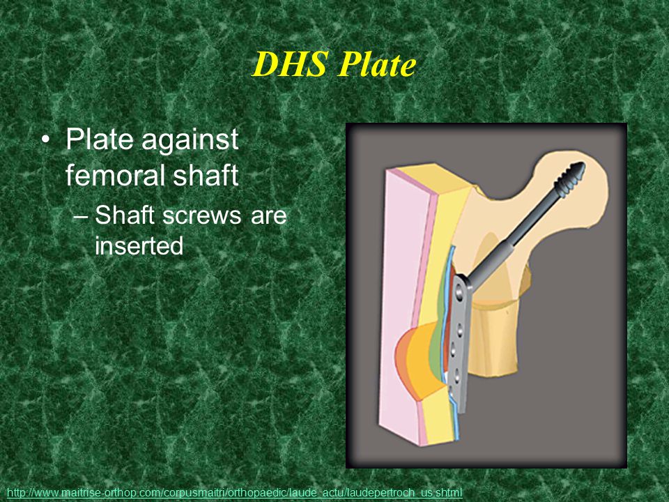
17
DHS Plate Plate against femoral shaft Shaft screws are inserted
18
DHS Problems With the plate attached to the bone
Bone below the plate is at an increased risk of a stress fracture Quality of bone is important Procedure will vary among patients with healthy or osteoporotic bone

19
Metal: Rough & Polished
Materials Composite Metal: Rough & Polished Polymer Ceramic

20
Bio Materials Synthetic materials Non viable material
Interacts with biological systems Corrosion Debris To augment or replace tissues and their functions

21
Types of materials Metals Composites Polymers Ceramics
Polyethylene (PE) Silicone Ceramics Bone cement (PMMA) Biodegradable
 Silicone. Ceramics. Bone cement (PMMA) Biodegradable.")
22
Metals Titanium Cobalt-chromium-molybdenum Stainless Steel
Chemical Make-up Ti6Al4V 30-60% Co 20-30% Cr 7-10% Mo Cr, Ni, Mo Cr: oxide layer when dipped in Nitric acid (reduced corrosion) Young’s Modulus 110 GPa 200 GPa 190 GPa (used with cement) Benefits Yield strength; Ti > Stainless Steel Stronger and more corrosion resistant than stainless steel; Excellent resistance to fatigue, cracking, and stress Strong, cheap, relatively biocompatible; annealed, cold worked or cold forged; relatively ductile-contouring of plates and wires Uses Cementless joint replacements (total knee arthroplasty); Fracture fixation devices Total joint arthroplasty (usually fixed with cement); Need to be inserted with a lower modulus polymer cement for fixation to prevent stress shielding of surrounding bone Rarely used in new designs in joint replacement; Fracture fixation devices Problems Poor wear characteristics *varies with smooth or porous surface Co, Cr, Mo known to be toxic in ionic form; High modulus Excessively corrosive in some cases Susceptible to fatigue cracking Very high modulus PMMA cement may cause fracture or tissue reaction
 Young’s Modulus. 110 GPa. 200 GPa. 190 GPa. (used with cement) Benefits. Yield strength; Ti > Stainless Steel. Stronger and more corrosion resistant than stainless steel; Excellent resistance to fatigue, cracking, and stress. Strong, cheap, relatively biocompatible; annealed, cold worked or cold forged; relatively ductile-contouring of plates and wires. Uses. Cementless joint replacements (total knee arthroplasty); Fracture fixation devices. Total joint arthroplasty (usually fixed with cement); Need to be inserted with a lower modulus polymer cement for fixation to prevent stress shielding of surrounding bone. Rarely used in new designs in joint replacement; Fracture fixation devices. Problems. Poor wear characteristics. *varies with smooth or porous surface. Co, Cr, Mo known to be toxic in ionic form; High modulus. Excessively corrosive in some cases Susceptible to fatigue cracking Very high modulus PMMA cement may cause fracture or tissue reaction.")
23
Composites Manufactured in several ways Young’s modulus = 200 GPa
Mechanical bonding between materials (matrix and filler) Chemical bonding Physical (true mechanical) bonding Young’s modulus = 200 GPa Benefits Extreme variability in properties is possible Problems Matrix cracking Debonding of fiber from matrix Examples: concrete, fiberglass, laminates, bone
 Chemical bonding. Physical (true mechanical) bonding. Young’s modulus = 200 GPa. Benefits. Extreme variability in properties is possible. Problems. Matrix cracking. Debonding of fiber from matrix. Examples: concrete, fiberglass, laminates, bone.")
24
Ceramics Materials resulting from ionic bonding of Benefits Examples
A metallic ion and A nonmetallic ion (usually oxygen) Benefits Very hard, strong, and good wear characteristics High compressive strength Ease of fabrication Examples Silicates , Metal Oxides - Al2O3, MgO Carbides - diamond, graphite, pyrolized carbons Ionic salts - NaCl, CsCl, ZnS
 Benefits. Very hard, strong, and good wear characteristics. High compressive strength. Ease of fabrication. Examples. Silicates , Metal Oxides - Al2O3, MgO. Carbides - diamond, graphite, pyrolized carbons. Ionic salts - NaCl, CsCl, ZnS.")
25
Ceramics (cont’d) Uses Problems Surface Replacement Joint Replacement
Very brittle & Low tensile strength Undergo static fatigue Very biocompatible Difficult to process High melting point Expensive

26
Polyethylene Ultra high molecular weight (UHMWPE) High density
Molecular weight 2-6 million Benefits Superior wear characteristics Low friction Fibers included Improve wear properties Reduce creep Used Total joint arthoplasty

27
Bone Cement Used to fill gaps between bone and implant
Example: total hip replacement If implant is not exactly the right size, gaps are filled regardless of bone quality

28
Bone Cement Polymethylmethacrylate
Mixed from powder polymer and liquid monomer In vacuum Reduce porosity Increase strength Catalyst (benzoyl peroxide) may be used Benefits Stable interface between metal and bone
 may be used. Benefits. Stable interface between metal and bone.")
29
Bone Cement (cont’d) Problems Inherently weak Exothermic reaction
Stronger in compression than tension Weakest in shear Exothermic reaction May lead to bone necrosis By handling improperly or less than optimally Weaker Extra care should be taken to Keep debris out of the cement mantle (e.g., blood, fat) Make uniform cement mantle of several mm Minimize voids in the cement : mixing technique Pressurize
 Make uniform cement mantle of several mm. Minimize voids in the cement : mixing technique. Pressurize.")
30
Biodegradable materials
Fixation of horizontal maxillary osteotomies Totally biodegradable self-reinforced polylactide (SRPLLA) plates Pins Poly-p-dioxanone (PDS) Benefits Gradual rate of absorption Allows an optimal transfer of support to bone as it heals
 plates. Pins. Poly-p-dioxanone (PDS) Benefits. Gradual rate of absorption. Allows an optimal transfer of support to bone as it heals.")
31
Mechanical Properties of IM
As Implant materials have to function as bones, the mechanical properties of interest are Elastic modulus Ultimate tensile strength They are listed in order of increasing modulus or strength (in next 2 slides)
")
32
Elastic Modulus in increasing order of strength
Cancellous bone Polyethylene PMMA (bone cement) Cortical bone Titanium alloy Stainless steel Cobalt-chromium alloy
 Cortical bone. Titanium alloy. Stainless steel. Cobalt-chromium alloy.")
33
Ultimate Tensile Strength in increasing order of strength
Cancellous bone Polyethylene PMMA (bone cement) Cortical bone Stainless steel Titanium alloy Cobalt-chromium alloy
 Cortical bone. Stainless steel. Titanium alloy. Cobalt-chromium alloy.")
34
Young’s Modulus Interactive Figure

35
Additional Resources

36
The End

37
Fracture Blisters Blisters on swollen skin overlaying a fracture
Most often at tibia, ankle or elbow Appear within hours of injury Complicate or delay surgical treatment if present preceding care No adverse affects if they appear following treatment

38
Varus Deformity at the knee
“A medial inclination of a distal bone of a joint from the midline” Can occur at any joint; Knee shown Before correction After corrective implants C A B

39
Oteotomy Removal of a wedge of bone to correct a (varus) deformity
High Tibial Osteotomy

40
Proximal Femur (Hip) Fractures
Risk of fracture effected by Age Gender Geographic location/ Ethnicity Mental capacity Bone strength Pre-existing medical conditions

Similar presentations


 ARTHROPLASTY –In biologic ‘old’ patients (> 60-80 yr)>")


 Trauma and post-traumatic arthritis Congenital deformities Bone tumors Avascular.>")


 Super Alloy Cement – to.>")

