Download presentation
Presentation is loading. Please wait.

1
Modern Services of Data Network Part I Communication
Presented by: Dr. Mohsen Kahani Ferdowsi University of Mashhad

2
Table of Contents Ethernet and 10GBE Internet Telephony WiFi Hotspot
xDSL Technology Fiber To The Home (FTTH)
")
3
Backbone Architecture Layers
Network designs are made up of three technology layers: The access layer which is the technology used in LANs The distribution layer connects LANs together The core layer connects different backbone networks together

4
Backbone Technologies

5
Fiber Distributed Data Interface (FDDI)
FDDI backbone protocol was developed in the 1980s and popular during the 80s and 90s. FDDI operates at 100 Mbps over a fiber optic cable. FDDI uses both a physical and logical ring topology capable of attaching a maximum of 1000 stations over a maximum path of 200 km. A repeater is need every 2 km. FDDI’s future looks limited, as it is now losing market share to Gigabit Ethernet and ATM.

6
FDDI Topology

7
FDDI’s Self-healing Rings

8
Asynchronous Transfer Mode (ATM)
Asynchronous Transfer Mode (ATM) (also called cell relay) is a technology originally designed for use in wide area networks that is now often used in backbone networks. ATM backbone switches typically provide point-to-point full duplex circuits at 155 Mbps (total of 310 Mbps).
 (also called cell relay) is a technology originally designed for use in wide area networks that is now often used in backbone networks. ATM backbone switches typically provide point-to-point full duplex circuits at 155 Mbps (total of 310 Mbps).")
9
Ethernet Timeline 1973 Ethernet Invented 2.93 Mbps
Mbps Ethernet Available Mbps Ethernet Available Mbps Ethernet Available Gbps Ethernet

10
FAST ETHERNET Fast Ethernet refers to a set of IEEE specifications that provide a low-cost Ethernet-compatible LAN operating at 100 Mbps. Basic idea is to keep all the old packet formats and protocols, just increase the speed.

11
Specifications: 100BASE-T4: 100 Mbps over twisted pair category 3 UTP 100BASE-TX: for category 5 UTP, full-duplex at 100 Mbps. 100BASE-FX: for fibre, full-duplex at 100 Mbps.

12
GIGABIT ETHERNET Fast is never fast enough
Migration of fast Ethernet to the desktop created bottlenecks at servers and switches. Gigabit Ethernet was designed to alleviate this congestion by providing faster backbone technology. The strategy for Gigabit Ethernet is the same as for fast Ethernet

13
GIGABIT ETHERNET – CONT.
Define a new medium, but retain the same CSMA/CD protocol and frame format as 10 Mbps and 100 Mbps Ethernet. The transmission medium is optical fibre over short distances. UTP and STP are also allowed.

14
Gigabit Ethernet Terminology
1000BASE-SX Short wavelength specification for Gigabit over MMF up to 300 meters 1000BASE-LX Long wavelength specification for Gigabit over MMF up to 550 meters or SMF up to 5 Km 1000BASE-CX Short haul specification for Gigabit over 4 conductor coax up to 25 meters 1000BASE-T Standard that can yield 100 meter distances

15
What’s new: 10 GbE Formally ratified on June 12, 2002 Ongoing need for more bandwidth Designation of bandwidth Uses 802.3ae 40 GbE on its way

16
10 GE: a new Ethernet 10 GE – designed from the beginning for access to long haul networks 40 km maximum distance specified by the standard … 1550nm lasers: optical amplifiers can be used to increase distance over dark fibre State of the art: 250 km demonstrated in Denmark by the EU ESTA project

17
The 10 GE WAN PHY 10GE introduces a gateway from LAN to the WAN by means of the WAN PHY Compatible with existing WAN infrastructure Transmission rate Encapsulation Partial use of the management bits of the SONET/SDH frame Today’s WAN PHY modules use SONET-compliant optical components traditional Router LTE OC192 WAN LTE Router OC192 3R 3R LTE LTE 3R WAN PHY WAN PHY novel 10GE switch/router 10GE switch/router

18
Why native Ethernet long haul?
More than 90% of the Internet traffic originates on an Ethernet LAN Data traffic on the LAN increases due to new applications Ethernet services with incremental bandwidth offer new business opportunities to carriers See IEEE Communications Magazine, Vol. 42, No. 3, March 2004, on additional benefits for both the enterprise and the service providers Why not native Ethernet ? Scalability, reliability, service guarantees … All of the above are active research areas Native Ethernet long haul connections can be used today as a complement to the routed networks, not as a replacement

19
Demo during ITU Telecom World '03
Cisco ONS 15454 Force10 E 600 Force10E 600 HP Itanium-2 Ixia 400T Intel Xeon 10GE WAN PHY 10GE LAN PHY OC192c Ottawa Toronto Chicago Amsterdam Geneva 10 GE WAN PHY over an OC-192c circuit using lightpaths provided by SURFnet and CANARIE 9.24 Gbps using traffic generators 6 Gbps using UDP on PCs 5.65 Gbps using TCP on PCs

20
Results on the transatlantic 10 GE
Single stream UDP throughput Single stream TCP throughput Data rates are limited by the PC, even for our memory-to-memory tests UDP uses less resources than TCP on high bandwidth-delay product networks

21
WAN PHY over DWDM Direct lambda access from the provider is required
Force10 E600 HP Itanium-2 DWDM Ixia 400T 10 GE WAN 10GE LAN Intel Xeon Force10 E600 HP Itanium-2 Ixia 400T 10 GE WAN DWDM 10GE LAN Amsterdam Geneva HP Itanium-2 Direct lambda access from the provider is required The DWDM transceiver card as “LTE”

22
10GBASE-T Objectives Keeping it Ethernet
Preserve the 802.3/Ethernet frame format at the MAC Client service interface Preserve min. and max. frame size of current Std. Support star-wired local area networks using point-to-point links and structured cabling topologies Keeping it 10 Gigabit Ethernet Support full duplex operation only Support a speed of Gb/s at the MAC/PLS service interface Compatibility with 802.3 Support Clause 28 auto-negotiation To not support 802.3ah (EFM) OAM unidirectional operation Support coexistence with 802.3af (DTE Power via Ethernet)
 OAM unidirectional operation. Support coexistence with 802.3af (DTE Power via Ethernet)")
23
10GBE Applications

24
10GBE-T Importance Faster network link speeds provide new generation of systems Modular switches and servers Backplanes and switch fabrics aggregate to support multiple 10GBASE-T ports Servers with faster I/O subsystems (i.e. PCI Express™) Low cost solutions are market stimulus 10GBASE-CX4 is a step in the right direction, but limited reach 10GBASE-T: Addresses PHY costs concerns in Enterprise market Enhances reach and conforms to structured cabling environments Lower cabling costs Installation practices are well-known Ease of installation Cost of termination
 Low cost solutions are market stimulus. 10GBASE-CX4 is a step in the right direction, but limited reach. 10GBASE-T: Addresses PHY costs concerns in Enterprise market. Enhances reach and conforms to structured cabling environments. Lower cabling costs. Installation practices are well-known. Ease of installation. Cost of termination.")
25
Comparison of 10GBE & GBE

26
10GBE-T Performance With the 4 connector model and proposed signaling:
100m on Class F (Cat 7) > 55m on Class E (Cat 6) operating beyond the specified frequency range 100m on the new cabling being defined by cabling standards groups (derivative of Class E/Cat 6) 20 to 60m on Class D (Cat 5e) was discussed Requires operation beyond the specified frequency range No consensus achieved on extending the specification Increase in system margin and/or reach are possible: – Several techniques have been presented in the SG: Analog signal conditioning Alien noise suppression Improvements in the cabling specification
 > 55m on Class E (Cat 6) operating beyond the specified frequency range. 100m on the new cabling being defined by cabling standards. groups (derivative of Class E/Cat 6) 20 to 60m on Class D (Cat 5e) was discussed. Requires operation beyond the specified frequency range. No consensus achieved on extending the specification. Increase in system margin and/or reach are possible: – Several techniques have been presented in the SG: Analog signal conditioning. Alien noise suppression. Improvements in the cabling specification.")
27
ATM vs. Switched Ethernet
ATM is a switched network, but differs from switched Ethernet in four ways: 1. ATM uses small, fixed-length packets of 53 bytes (called cells). Ethernet frames are variable and can be up to about 1 kilobyte in length. 2. ATM provides no error correction on the user data. Switched Ethernet does error correction. 3. ATM uses virtual channels instead of the fixed addresses used by traditional data link layer protocols such as switched Ethernet. 4. ATM prioritizes transmissions based on Quality of Service (QoS), while switched Ethernet does not.
. Ethernet frames are variable and can be up to about 1 kilobyte in length. 2. ATM provides no error correction on the user data. Switched Ethernet does error correction. 3. ATM uses virtual channels instead of the fixed addresses used by traditional data link layer protocols such as switched Ethernet. 4. ATM prioritizes transmissions based on Quality of Service (QoS), while switched Ethernet does not.")
28
Enterprise Backbone Technology Trends
Organizations are moving to Ethernet-based collapsed backbones with switched LANs or VLANs. Gigabit Ethernet use is growing. FDDI seems to be on its way out. ATM, while still popular in WANs, is also losing ground to Gigabit Ethernet. Taken together, it appears that Ethernet use will dominate the LAN and backbone.

29
The Ideal Backbone? The ideal network design is likely to include the following characteristics: Combined use of layer 2 and layer 3 Ethernet switches. The access layer (LANs) uses 10/100 Layer 2 Switches running Cat 5 or Cat 6 twisted pair cables (Cat 6 enables the move to 1000BaseT). The distribution layer uses Layer 3 Ethernet Switches that use 1000BaseT or fiber, Cat 6 or Cat 7 TP. The core layer uses Layer 3 Ethernet Switches running 10GbE or 40GbE over fiber. Reliability is also increased in the network by using redundant switches and cabling.
 uses 10/100 Layer 2 Switches running Cat 5 or Cat 6 twisted pair cables (Cat 6 enables the move to 1000BaseT). The distribution layer uses Layer 3 Ethernet Switches that use 1000BaseT or fiber, Cat 6 or Cat 7 TP. The core layer uses Layer 3 Ethernet Switches running 10GbE or 40GbE over fiber. Reliability is also increased in the network by using redundant switches and cabling.")
30
Internet Telephony vs. Telephony over Internet
1

31
Telephony over Internet
Emulation of Telephony Services on Internet dumb end terminals (cable modems) 12-digit keypad UI transparency of services it is important! Primary motivation cost savings non-telcos can enter Cost savings are transient Whats in it for customers???? 2
 12-digit keypad UI. transparency of services. it is important! Primary motivation. cost savings. non-telcos can enter. Cost savings are transient. Whats in it for customers 2.")
32
Branch Office Application

33
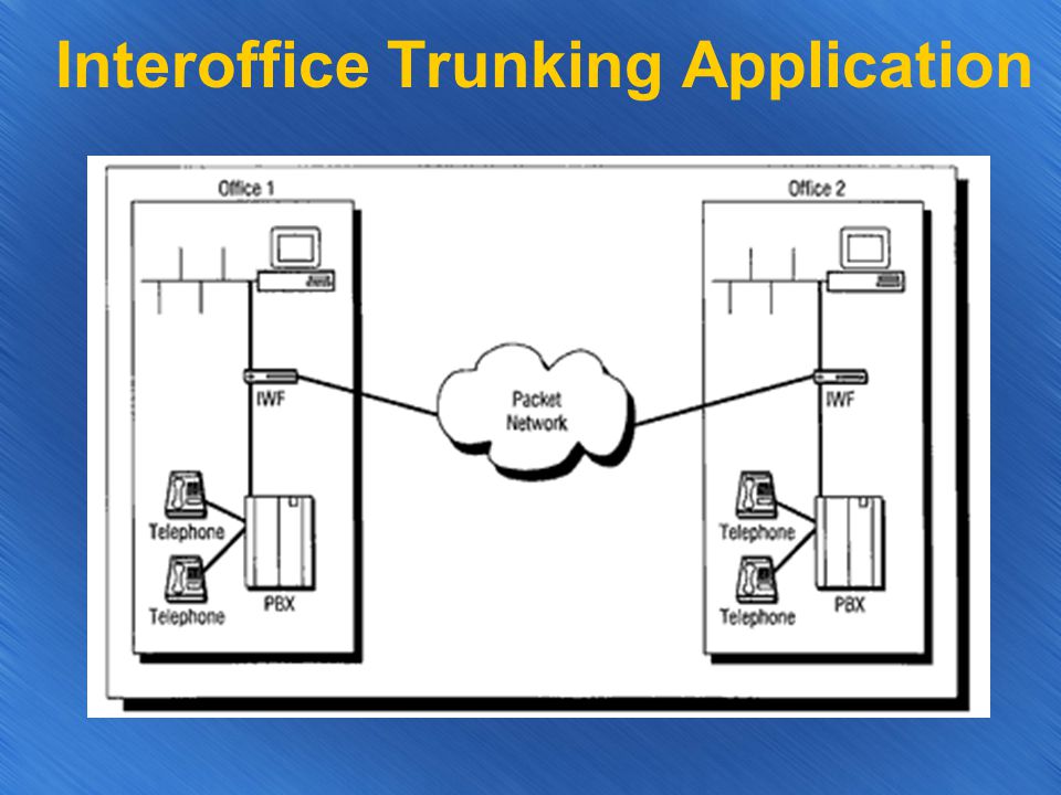
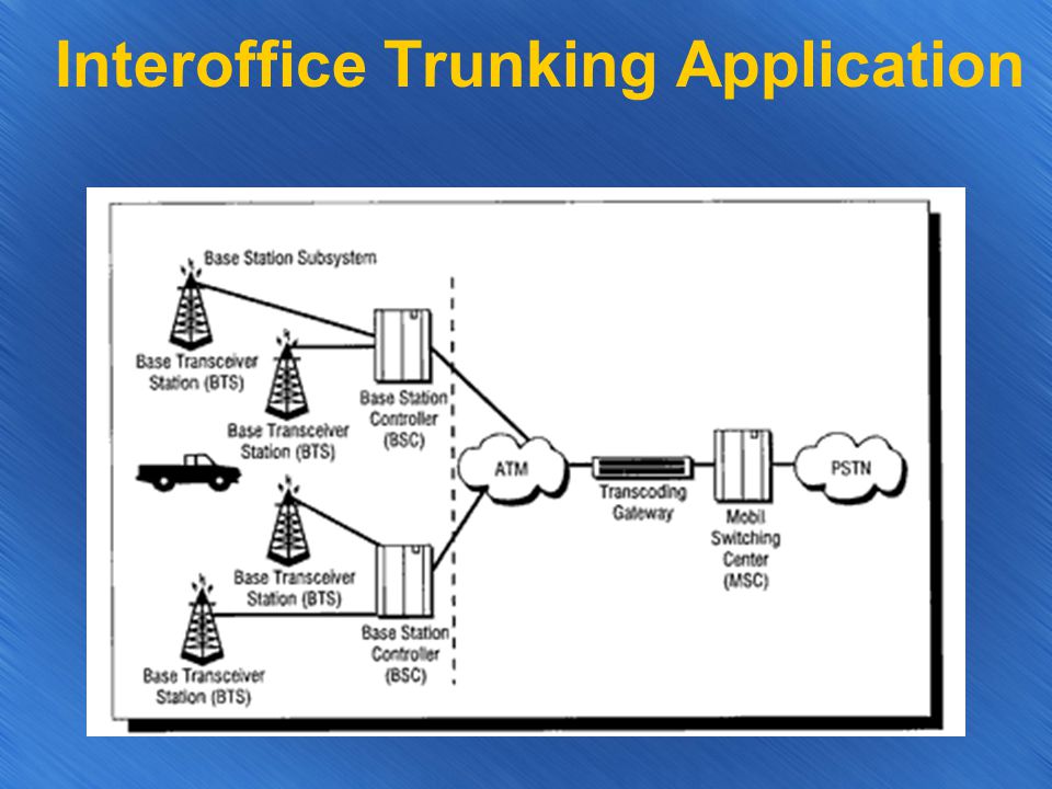
Interoffice Trunking Application
34
Interoffice Trunking Application
35
Internet Telephony What is it? Use your PC as a telephone Motivation
Cost - Advanced Services Higher fidelity voice 3D voice reconstruction Integration with calendar Complex call management Mobility Powerful voic systems; integrated messaging Multiparty calls Video/whiteboard Compression, silence suppression

36
Internet Telephony Integrate telephony services with web email
instant messaging and presence text chat interactive games Web Games Presence Interactive Communications voice video Chat IM INTERNET TELEPHONY 3

37
New Services Integration causes service multiplication
20 voice services X 20 web services = 400 integrated service possibilities not all make sense New services = revenue opportunities Examples IM Notify when busy subscriber gets instant messages when friends telephones (IP or POTS) available Call redirect to web web page returned instead of busy signal Web IVR web page of menus, final choice rings phone 4
 available. Call redirect to web. web page returned instead of busy signal. Web IVR. web page of menus, final choice rings phone. 4.")
38
More Services Shared web browsing IM notifications of conference join
talk and browse jointly Transfer to Caller is disconnected and mail tool pops up call logs Unanswered calls cause notifications IM notifications of conference join On a conference bridge, instant message indicates participant joins/leaves Web call-ID web page of caller pops up when phone rings 5

39
Who can get services? Advanced services can be offered to PSTN end systems too! VXML consortium technology for providing web content on phone allows web services to be exposed Speech to text sending web browsing IM Text to speech Instant messages 6

40
How to do it? Integrated services = integrated server
SIP server/gatekeeper SMTP/IMAP/POP client and server Presence and IM server Web access Conference services access Mail Services IM and Presence Services Intelligent Integrated Communications Server Conference Services Web Services Directory Services 7

41
What does it have to do with ISP’s?
IP telephony is point to point Looks like data to ISP Extra Services! Network QoS support Processing Services Gateway Services Database Services IN Services

42
Gateway Services IP to PSTN PSTN to IP PSTN to PSTN, IP long distance
IP to IP, PSTN long distance ISP NETWORK GW GW PSTN

43
Gateway Services IP to PSTN PSTN to IP
Billing - accounts, credit cards, e-cash Discovery - based on cost, proximity, codec/protocol support, administrator Non-locality problem - partnerships; billing! PSTN to IP IP endpoint identification IP address Speech recognition alphabet keys telephone numbers Telephone Numbers International, area code, mixed, 10-XXX access Gateway Selection

44
Gateway Services IP-PSTN-IP (access bypass) Discovery problem
use ISP as LEC improved voice quality Discovery problem Proximity of GW to IP address Traditional routing? Phone connection transcode for voice only? Modem - IP links-on-demand Billing PSTN-IP-PSTN (long distance bypass) Nearly identical to IP to PSTN case Selection of gateway similar to PSTN to IP case ISP can now be a long-distance provider - ITSP
 Nearly identical to IP to PSTN case. Selection of gateway similar to PSTN to IP case. ISP can now be a long-distance provider - ITSP.")
45
Gateway Architecture Basic HW Components
PC DSP card Telephony card (Dialogic, Natural Microsystems) Ethernet card Gateways are a SOFTWARE problem call control, billing, accounting, net protocols, management, etc. PSTN CARD DSP CARD ETHERNET CPU PC - WIN NT or UNIX T1, ISDN, analog
 Ethernet card. Gateways are a SOFTWARE problem. call control, billing, accounting, net protocols, management, etc. PSTN CARD. DSP CARD. ETHERNET. CPU. PC - WIN NT or UNIX. T1, ISDN, analog.")
46
Gateway Features Codecs Authentication/authorization Accounting
GSM, G.729, G.723, Elemedia, G.728, G.726 Authentication/authorization Accounting Protocol compliance - H.323, H.332, SIP Management Billing credit cards, account, debit cards, phone cards, SET $/port Telephony termination analog, T1, T3, ISDN PRI IP termination Ethernet, Frame Relay, T1,T3, ATM/SONET Routing static, database access, polling IVR System User Profiles Bridging

47
Main Vendors Lucent Technologies Vienna Systems VocalTech Micom
Enterprise and Carrier grade gateways Vienna Systems VocalTech Micom NetiPhone Netspeak PhoNet Ericsson Ascend ….. Several HUNDRED vendors Prediction: Small players will lose to big, carrier-grade capable vendors

48
ITSP’s Internet Telephony Service Providers Several business models:
PSTN to PSTN, IP long distance Several business models: Run gateways, resell service to service providers Run gateways and service; perhaps partner with other such providers, also resell service to telcos and small ISP’s Run service only, lease gateways from resellers Run clearinghouse for settlements and billing agreements (Planet Telecom)
")
49
Database Services - User Location
How to determine IP address of a person you wish to talk to Dynamic IP addresses make this a very hard problem Several approaches Single database -based Location service provided by your ISP

50
User Location Email based
Single Database User “registers” with well-known database when logging in, “unregisters” when leaving Registration binds a unique identifier (your name) to IP address To call a person, you query database with identifier, and get IP address back Model used by H.323 (Gatekeepers) Initial model used by most IP telephony software - each software maintains its own listing Can have global directories - Four11 Big drawback - requires central directory for whole planet - scalable? Who will run it? based Your telephone address is your address You register with a directory server associated with your domain Other users find your directory server in DNS Can then query directory server to get your IP address Scalable, uses existing infrastructure; names mnemonic (usually); portability; multiple names, single and telephony identifier
 to IP address. To call a person, you query database with identifier, and get IP address back. Model used by H.323 (Gatekeepers) Initial model used by most IP telephony software - each software maintains its own listing. Can have global directories - Four11. Big drawback - requires central directory for whole planet - scalable Who will run it based. Your telephone address is your address. You register with a directory server associated with your domain. Other users find your directory server in DNS. Can then query directory server to get your IP address. Scalable, uses existing infrastructure; names mnemonic (usually); portability; multiple names, single and telephony identifier.")
51
Database Services - Voicemail
Your PC is not connected to Internet 24 hours per day Via Location Database, ISP knows when you are an are not connected - can provide voic service One method: Location server directs caller to contact voic server; caller leaves message Location server sends you with a URL When you log in, you click on URL - brings you to a web page on the voic server and gets a Java applet Applet lets you sort and file messages, play them out, forward, rewind, etc. Big plus: Don’t even need IP telephony software for voic , just !

52
IN Services IN = Intelligent Networking
Existing technology which lets you create services in telephone network via direct control over switches Basic idea - let IP hosts (ISP servers) set up services in telephone network Examples Click-to-dial Click-for-faxback Click-for-content
 set up services in telephone network. Examples. Click-to-dial. Click-for-faxback. Click-for-content.")
53
IN Services Click for content Click to Dial
Web page has link to call customer service department, and a form entry to fill in your phone number Click on link - web server instructs telephone switches to connect you to customer service Your phone rings, then customer service Call billed to company Click for faxback Same as above, except your phone is a fax machine, and customer service phone is a fax bank Gives you instant access to fax databases Click for content You wish to listen to an audio file over the telephone Click on web page, fill in form with telephone number. Media server (either in PSTN or on Internet) calls your telephone You control playback via telephone tones and/or PC controls
 calls your telephone. You control playback via telephone tones and/or PC controls.")
54
How to do it all? Lots of protocols involved
RTP (Real Time Protocol) H.323 (ITU Spec for Multimedia Conferencing) SIP (Session Initiation Protocol) RTSP (Real Time Streaming Protocol) LDAP (Lightweight Directory Access Protocol) Lots still under development Gateway Discovery IN Services User Location Skip Details
 H.323 (ITU Spec for Multimedia Conferencing) SIP (Session Initiation Protocol) RTSP (Real Time Streaming Protocol) LDAP (Lightweight Directory Access Protocol) Lots still under development. Gateway Discovery. IN Services. User Location. Skip Details.")
55
RTP/RTCP Real Time Control Protocol RTP port + 1 Used for
RTP provides for Real time transport Resequencing Payload type identification Intra and Inter media synchronization Encryption Multicast Per User demultiplexing - SSRC RTP does not Provide QoS Require RSVP RTP is a framework Specific payload formats defined for H.263, etc. UDP Port numbers based on application Real Time Control Protocol RTP port + 1 Used for QoS Reporting Sender reports: packets sent, bytes sent Receiver reports (per sender): loss, delay, jitter observed; instantaneous and cumulative Media Synchronization NTP and RTP Timestamp correlation Loose Session Control Hello, Bye messages SDES - , username, CNAME, etc
: loss, delay, jitter observed; instantaneous and cumulative. Media Synchronization. NTP and RTP Timestamp correlation. Loose Session Control. Hello, Bye messages. SDES - , username, CNAME, etc.")
56
H.323 Monstrous ITU Specification for Multimedia Conferencing
H.323 is an umbrella - many sub-specifications: H.225.0: Call control, RAS H.245: Capabilities Exchange, Indications, Notifications H Large Group conferences H Supplementary Services G.711, G.728, G.729, G speech coders H.261, H video coders H Interworking between H.323 and other H.XXX standards H Security for H.323 terminals

57
H.323 Elements H.323 Terminal MCU MC MP Gatekeeper Gateway
PC with H.323 software MCU Multipoint Control Unit Mixes audio and video MC Multipoint Controller Performs signaling for centralized conferences MP Multipoint Processor Actual device for mixing audio and video Gatekeeper Controls sessions Performs user location and registration Performs admission control Reroutes signaling Processes RAS (Registration, Admissions, Status) from H.323 terminals Gateway Interface between H.323 systems and other systems - PSTN, H.324 (PSTN multimedia), H.320 (ISDN multimedia), H.321 (ATM multimedia)
 from H.323 terminals. Gateway. Interface between H.323 systems and other systems - PSTN, H.324 (PSTN multimedia), H.320 (ISDN multimedia), H.321 (ATM multimedia)")
58
H.323 in an ISP Network TO PSTN GATEWAY MCU (MP and MC) ISP IP NETWORK
POP-IN-A-BOX GATEWAY H.323 TERMINALS TO PSTN GATEKEEPER DATABASE STORAGE

59
Basic H.323 Call Flow TCP SYN TCP SYN ACK H.225 SETUP H.225 CONNECT
CAPABILITIES/MASTER-SLAVE CAPABILITIES/MS-ACK/CAP-ACK CAP-ACK/MS-ACK/OPEN AUDIO OPEN ACK/ OPEN AUDIO OPEN ACK AUDIO DATA

60
Session Initiation Protocol
IETF Standard Lightweight multimedia session initiation, call control, capabilities exchange, and user location Based on http; textual, reuses authentication mechanisms Provides full telephony services: call forward, transfer, 800,900 style numbers Supports personal mobility Addressing based on address Uses SDP (Session Description Protocol) for expressing capabilities Basic methods: INVITE - ask a user to join a session; callee responds with accept or reject, along with a slew of reason codes OPTIONS - obtain capabilities, but don’t invite CONNECTED - acknowledges acceptance BYE - for transfers and session terminations REGISTER - Allows a user to register with a SIP server
 for expressing capabilities. Basic methods: INVITE - ask a user to join a session; callee responds with accept or reject, along with a slew of reason codes. OPTIONS - obtain capabilities, but don’t invite. CONNECTED - acknowledges acceptance. BYE - for transfers and session terminations. REGISTER - Allows a user to register with a SIP server.")
62
Wi-Fi Hotspot A specific geographic location in which an access point provides public wireless broadband services to mobile visitors. Hotspots are often located in heavily populated places such as airports, convention centers, coffee shops, hotels, and so on

63
HotSpot Motivation an increasing trend toward being always on, always active, and always connected and delivering high-speed data and Internet applications to wireless subscribers

64
Wireless Taxonomy Wireless WANs (WWAN)/Nomadic Networks High power, long range Various cellular and related technologies (GSM, GPRS, CDPD, TDMA, etc.) Wireless LANs (WLANs) Medium power, medium range IEEE and similar technologies Wireless Personal Area Networks (WPANs) Low power, short range Bluetooth, HomeRF, IrDA, IEEE technologies PAL/ Hotspot Service
/Nomadic Networks High power, long range Various cellular and related technologies (GSM, GPRS, CDPD, TDMA, etc.) Wireless LANs (WLANs) Medium power, medium range IEEE and similar technologies. Wireless Personal Area Networks (WPANs) Low power, short range Bluetooth, HomeRF, IrDA, IEEE technologies. PAL/ Hotspot Service.")
65
Standards – IEEE 802 Bluetooth/ IEEE 802.15
Derivation of Bluetooth 1.x spec and more meaningful standards for developments relate to Bluetooth applications profiles, operates at 2.4 GHz IEEE Basic standard for WLANs which was developed in the late 1990s supporting speeds up to 2 Mbps IEEE b Basic standard for WLANs. An extension of the IEEE specifications, supporting speeds of 1, 2, 5.5, and 11 Mbps. Operates at 2.4 GHz IEEE a High-speed WLAN supports 6, 12, and 24 Mbps (mandatory), 9, 18, 36, 48, and 54 Mbps (optional), operating at 5 GHz
, 9, 18, 36, 48, and 54 Mbps (optional), operating at 5 GHz.")
66
Standards – IEEE 802 (cont’)
IEEE e Revision of MAC standards, this provides QoS capabilities needed for real-time applications like IP telephony and voice IEEE g A new standard for 2.4 GHz WLANs, this provides a bump in the data rate to 20+ Mbps (aiming at 54 Mbps), but backward-compatible products will not arrive soon IEEE i Mired in technical debate and politics, this is critical to WLAN market expansion, but delays and indecisiveness may make it meaningless if de facto standards emerge IEEE Its goal is to define physical and MAC standards for fixed point-to-multipoint broadband wireless access (BWA) systems IEEE 802.1x Security framework for all IEEE 802 networks, this is one of the key components of future multivendor interoperable wireless security systems, but implementation will not be simple
, but backward-compatible products will not arrive soon. IEEE i. Mired in technical debate and politics, this is critical to WLAN market expansion, but delays and indecisiveness may make it meaningless if de facto standards emerge. IEEE Its goal is to define physical and MAC standards for fixed point-to-multipoint broadband wireless access (BWA) systems. IEEE 802.1x. Security framework for all IEEE 802 networks, this is one of the key components of future multivendor interoperable wireless security systems, but implementation will not be simple.")
67
Standards – WWAN 2G/2.5G/3G GPRS EDGE TDMA GSM CDMA WCDMA CDMA 2000 1x
2G standard used by AT&T wireless services GSM 2G standard which is most widely used in Europe, based on TDMA CDMA 2G standard. It is the leading air interface in North America, patented by Qualcomm GPRS 2.5G standard for WWANs based on GSM systems deployed throughout Europe and in other parts of the world. GPRS is an IP-based, packet-data system providing theoretical peak data rates of up to 160 Kbps EDGE Pushes the GPRS data rate to 384 Kbps, but upgrades may be costly for carriers CDMA x 2.5 G standard for WWANs, this provides more efficient voice and packet-switched data services with peak data rate of 153 Kbps CDMA xEV Qualcomm is pushing 1xEV as an evolution of 1x technology. It uses a 1.25 MHz CDMA radio channel dedicated to and optimized for packet data, and has throughputs of more than 2 Mbps CDMA x 3G standard for WWANs, this uses the same architecture as 1x. It offers 384 Kbps outdoors and 2 Mbps indoors, but operators will likely need to wait for new spectrum WCDMA 3G standard similar to CDMA 2000 but uses wider 5 MHz radio channels. It provides data rates up to 2 Mbps, but more spectrum needs to be allocated in some areas

68
Technologies - WLANs Wireless PHYs CSMA/CA
Spread Spectrum (SS): a wideband radio frequency (RF) technique that trades off bandwidth efficiency for reliability, integrity, and security Infrared (IR) technology: use very high frequencies just below visible light to carry data. IR cannot penetrate opaque objects. Inexpensive. Limited range. CSMA/CA Designed to solve hidden node situation in wireless communication to prevent packet collision
: a wideband radio frequency (RF) technique that trades off bandwidth efficiency for reliability, integrity, and security. Infrared (IR) technology: use very high frequencies just below visible light to carry data. IR cannot penetrate opaque objects. Inexpensive. Limited range. CSMA/CA. Designed to solve hidden node situation in wireless communication to prevent packet collision.")
69
Technologies – WPANs Bluetooth
A low-cost, low-power, short-range radio link for mobile devices and WAN/LAN APs. It offers fast and reliable digital transmission of both voice and data over the globally available 2.4 GHz ISM band The raw throughput is 1 Mbps, and the actual data rate is 728 Kbps

70
Technologies - WWANs Up to now, WWAN architectures have focused on voice services or at most low-speed circuit-mode data. The plans for the future are to add higher-speed data services. Hotspot networks continue to be best served by WLANs and WPANs for the next two to three years rather than WWANs Major cellular architectures include TDMA, cdmaOne, GSM/GPRS. CDMA2000 and W-CDMA have limited support for data services

71
Wireless Internet – From a Business Perspective
TabletPC PC, Mac, Web station Business Users Must Haves To be able to Send/Receive and Store messages seamlessly from any device. Access all available electronic data related to their work from most devices. Central Network Based Address Book Access and Schedule Business and Personal related Appointments, Events, Reminders… Internet Kiosk In-flight & Car Entertainment enterprise iTV WAP, i-Mode, PDA

72
What does the enterprise need ?
Collaborative Wireless Applications that Increase Personal Productivity and which are: Secure and Reliable Easy to Deploy & Maintain Modular to Allow for changes in size and technology Anywhere, Anyhow, Anytime Access Low TCO and Affordable Access

73
Operators Network Environment
LAN WiFI PC TabletPC Laptop PDA Appliances Internet TelcoxSP Internet Broadband CDMA / GPRS WiFi hotspots Broadband Phone WiFI PC TabletPC Bluetooth Interactive TV Game console Phone PDA Laptop

74
What are the Opportunities for Carriers ?
Offer Collaborative Wireless Internet Solutions to the Enterprise market thus allowing them to : Increase ARPU Whether billed directly or via cross billing, business users will be forced to connect to your services, thus increasing your revenues. Increase Customer Loyalty As data becomes centric, the companies will be less apt to change the storage location Operators can target individual business users by being taking a “complete provider approach” especially for address book and calendar and file storage.

75
Operator Business Models
Packaging Models, subscription based Internet Access bundle One broadband connection One WiFi WLAN router Collaborative Messaging Applications Address book Calendar File storage Optional Interface Customizations to Large Enterprises

76
Operator Business Models
Pay-per-use Models Internet Access WiFi hotspot prepaid hours GPRS connections with billed upon kb transfer in/out Voice access on per minute usage Messaging Applications , address book, calendar, file storage applications are available SMS/MMS bundle

77
Digital Subscriber Line Technologies (DSL)
")
78
Definition of Terms Used
DSL stands for Digital Subscriber Line High Speed Data Subscriber Line Upstream & Downstream Symmetric and Asymmetric No Dial Ups necessary Overview DSL – DSL is an abbreviation for Digital Subscriber Line. High Speed Data – DSL technology provides voice and high speed data telecommunications over the standard telephone line at rates approximately 30 times faster (and growing) than the fastest traditional modems. Subscriber Line – Subscriber Line refers to the line connecting the individual subscriber (i.e. household or business premises) to the exchange. Upstream & Downstream – The diagram below shows upsteam from the user to the exchange and downstream form the exchange to the user. Symmetric and Asymmetric – The DSL family consists of two branches: symmetric and asymmetric. Symmetric DSL services provides identical data rates upstream and downstream where as asymmetric DSL provides relatively lower rates upstream compared with the downstream rate. No Dial Up – No Dial Up refers to no dial up to an exchange is necessary as is with conventional modems used for customers to connect to the internet. Exchange User downstream upstream
 than the fastest traditional modems. Subscriber Line – Subscriber Line refers to the line connecting the individual subscriber (i.e. household or business premises) to the exchange. Upstream & Downstream – The diagram below shows upsteam from the user to the exchange and downstream form the exchange to the user. Symmetric and Asymmetric – The DSL family consists of two branches: symmetric and asymmetric. Symmetric DSL services provides identical data rates upstream and downstream where as asymmetric DSL provides relatively lower rates upstream compared with the downstream rate. No Dial Up – No Dial Up refers to no dial up to an exchange is necessary as is with conventional modems used for customers to connect to the internet. Exchange. User. downstream. upstream.")
79
Types of DSL Technologies
Asymmetric DSL (ADSL) ADSL Light Rate-Adaptive DSL (RADSL) ADSL 2 ADSL 2+ High bit rate DSL (HDSL) Symmetric DSL (SDSL) Single-pair high speed DSL (SHDSL/HDSL2) Very High Data Rate DSL (VDSL) Other DSL Technologies: IDSL & VoDSL
 ADSL Light. Rate-Adaptive DSL (RADSL) ADSL 2. ADSL 2+ High bit rate DSL (HDSL) Symmetric DSL (SDSL) Single-pair high speed DSL (SHDSL/HDSL2) Very High Data Rate DSL (VDSL) Other DSL Technologies: IDSL & VoDSL.")
80
ADSL Fast Broadband connection Always On Asymmetric Dedicated Channel
Typical Data Rates in Australia today are : 1.5 Mbits/s downstream & 512 kbits/s upstream Typical Reach: up to 3 km Coexists with POTS (Plain Old Telephone Service) ITU-T Recommendation G992.1 Description of ADSL Fast Broadband – ADSL is a technology that permits fast broadband data rates typically used for the internet. Always On - Because voice and data are transmitted separately, what the user receives is an uninterrupted, high-speed Internet access that is always on-line. There is no logging on and off, no busy signals and no waiting as users would experience with traditional modems. Asymmetric – ADSL is an asymmetric DSL service providing relatively lower rates upstream compared with the downstream rate. This feature coincides with the type of applications offered through ADSL such as web browsing where the data downloaded by the user is much higher than the data uploaded towards the exchange. Dedicated Channel – If the user orders a 1.5 Mbits/s line, they will get a 1.5 Mbits/s line dedicated to them. Cable modems, on the other hand, share bandwidth with several neighbours per media which can affect the transmission speeds. Data Rates – Typical data rates for ADSL in Australia today are 1.5 Mbits/s downstream and 512 Kbits/s upstream. The data rates will vary depending on distance and line distortions. Typical Reach – The typical reach for ADSL services are approximately 3 km. Analogue/Digital – ADSL is a technology that allow the transmission of both POTS (analogue) and ADSL (digital) services on the one twisted pair ITU-T Recommendation G992.1
 ITU-T Recommendation G Description of ADSL. Fast Broadband – ADSL is a technology that permits fast broadband data rates typically used for the internet. Always On - Because voice and data are transmitted separately, what the user receives is an uninterrupted, high-speed Internet access that is always on-line. There is no logging on and off, no busy signals and no waiting as users would experience with traditional modems. Asymmetric – ADSL is an asymmetric DSL service providing relatively lower rates upstream compared with the downstream rate. This feature coincides with the type of applications offered through ADSL such as web browsing where the data downloaded by the user is much higher than the data uploaded towards the exchange. Dedicated Channel – If the user orders a 1.5 Mbits/s line, they will get a 1.5 Mbits/s line dedicated to them. Cable modems, on the other hand, share bandwidth with several neighbours per media which can affect the transmission speeds. Data Rates – Typical data rates for ADSL in Australia today are 1.5 Mbits/s downstream and 512 Kbits/s upstream. The data rates will vary depending on distance and line distortions. Typical Reach – The typical reach for ADSL services are approximately 3 km. Analogue/Digital – ADSL is a technology that allow the transmission of both POTS (analogue) and ADSL (digital) services on the one twisted pair. ITU-T Recommendation G")
81
Equipment Used in ADSL Transmission Line DSLAM (ATU-C)
DSL Modem (ATU-R) Splitter Equipment & Setup Transmission Line – The Transmission line is the medium over which the data is transferred from the user to the exchange. DSL technology uses copper twisted pair. DSL Modem – The DSL Modem devices are situated at the customer premises and at the exchange. They are also known through the ITU as an ATU-R (ADSL transceiver unit – remote) or ATU-C (ADSL transceiver unit – central office). They convert the digital signals to and from analogue signals for transmission over the conventional copper twisted pairs. The modems can be either internal or external to the users computer. DSLAM (DSL Access Module) – A DSLAM is known technically as a number of ATU-Cs in the one module and is located at the exchange, it consists of several DSL modems and communicates between the telephone network and the end users DSL modem via the transmission line. The DSLAM concentrates multiple digital access lines onto a backbone network to be transmitted to other data networks such as the internet. Splitter – The splitter device resides at both the exchange and end user locations. The Splitter divides an xDSL signal into separate voice and data outputs. The splitter effectively separates the existing telephone signal from the high speed data signal so as POTS can coexist with ADSL on the one twisted copper pair. The splitter filters out the high frequencies.
 Splitter. Equipment & Setup. Transmission Line – The Transmission line is the medium over which the data is transferred from the user to the exchange. DSL technology uses copper twisted pair. DSL Modem – The DSL Modem devices are situated at the customer premises and at the exchange. They are also known through the ITU as an ATU-R (ADSL transceiver unit – remote) or ATU-C (ADSL transceiver unit – central office). They convert the digital signals to and from analogue signals for transmission over the conventional copper twisted pairs. The modems can be either internal or external to the users computer. DSLAM (DSL Access Module) – A DSLAM is known technically as a number of ATU-Cs in the one module and is located at the exchange, it consists of several DSL modems and communicates between the telephone network and the end users DSL modem via the transmission line. The DSLAM concentrates multiple digital access lines onto a backbone network to be transmitted to other data networks such as the internet. Splitter – The splitter device resides at both the exchange and end user locations. The Splitter divides an xDSL signal into separate voice and data outputs. The splitter effectively separates the existing telephone signal from the high speed data signal so as POTS can coexist with ADSL on the one twisted copper pair. The splitter filters out the high frequencies.")
82
ADSL Limitations Frequency Response Crosstalk
Other Limitation to ADSL Services are: Bridge Taps Loading Coils Cable Joints RIMS Pair Gain Limitations Frequency Response – The copper twisted pair serves well for low frequency audio signals to 4 kHz, however the copper twisted pairs were never intended for high frequency transmission. As the frequency is applied to the copper twisted pair and increases, the attenuation of line also increases. XTalk – Crosstalk is the coupling of a signal from one copper twisted pair to another. Crosstalk occurs when some of a transmission signal is leaked from the cable to another. (There are two types of crosstalk NEXT and FEXT, NEXT is more serious as the signal interference levels are higher than FEXT). Bridge Taps – Is a section of a cable pair not on the direct path between the exchange and the user. A bridge tap increases the electrical loss on the pair. The ULL – Encompasses: Loading Coils – These devices are used to adjust the frequency response of a communications line to transfer audio signals better. They work well for audio however they do not permit the operation of xDSL signals. Cable Joints – this technique may be employed to extend the length of the twisted pair to the boundary of the serving area. Each splice used causes attenuation of the signals. RIMS – Remote Integrated Multiplexer are utilised in 5 – 10 % of serving areas and prevent the use of ADSL services. This problem can be overcome by connecting a DSLAM within the RIM. Putting DSLAMs within the RIMS has been ruled out for the time being due to crosstalk issues. Pair Gain – These devices are used to attach two (or more) residents from the one twisted pair to the exchange and as a consequence prevents the use of ADSL over the line.
. Bridge Taps – Is a section of a cable pair not on the direct path between the exchange and the user. A bridge tap increases the electrical loss on the pair. The ULL – Encompasses: Loading Coils – These devices are used to adjust the frequency response of a communications line to transfer audio signals better. They work well for audio however they do not permit the operation of xDSL signals. Cable Joints – this technique may be employed to extend the length of the twisted pair to the boundary of the serving area. Each splice used causes attenuation of the signals. RIMS – Remote Integrated Multiplexer are utilised in 5 – 10 % of serving areas and prevent the use of ADSL services. This problem can be overcome by connecting a DSLAM within the RIM. Putting DSLAMs within the RIMS has been ruled out for the time being due to crosstalk issues. Pair Gain – These devices are used to attach two (or more) residents from the one twisted pair to the exchange and as a consequence prevents the use of ADSL over the line.")
83
ADSL Line Coding & Modulation
What is line Coding Line coding techniques used with ADSL: DMT: (DMT) Discreet Multitone Modulation The transmission of several narrow sub-channels. Divides signals into 247 separate channels at 4 kHz. QAM/CAP: (QAM) Quadrature Amplitude and Phase Modulation Combines two different types of modulation; amplitude and phase. (CAP) Carrierless Amplitude and Phase Modulation. Similar to QAM, divides signals into three distinct bands. Technology Overview This Slide is actually a very detailed technical area What is Line Coding & Modulation – Line coding is about using as little bandwidth as possible and is the technique of putting out electrical pulses on a transmission medium such as copper twisted pair so as a receiver can then accurately interpret them. It enables efficient transmission. Line coding Techniques used with ADSL are: DMT – (Discreet MultiTone Modulation) is a technique that divides the signal into 247 separate channels each being 4 kHz. The technique monitors the channels, if the quality is impaired the signal will be shifted to another channel. QAM – (Quadrature Amplitude and Phase Modulation) is a technique that combines two different types of modulation amplitude and phase, to effectively triple or quadruple the information sent over the line. It allows the delivery of a large number of bits (characteristic of ADSL) per unit of bandwidth. CAP – (Carrierless Amplitude and Phase Modulation) is a technique very similar to QAM and operates by dividing the signals on the telephone line into three distinct bands; voice, upstream and downstream. These are some diagrams which represent DMT and QAM/CAP. voice from (0 – 4) kHz, upstream from (25 – 160) kHz and downstream from (240 – 1100) kHz. This modulation technique minimises the risk of interference Typically – Cap Based ADSL uses FDM and DMT based ADSL uses echo cancellation
 Discreet Multitone Modulation. The transmission of several narrow sub-channels. Divides signals into 247 separate channels at 4 kHz. QAM/CAP: (QAM) Quadrature Amplitude and Phase Modulation. Combines two different types of modulation; amplitude and phase. (CAP) Carrierless Amplitude and Phase Modulation. Similar to QAM, divides signals into three distinct bands. Technology Overview. This Slide is actually a very detailed technical area. What is Line Coding & Modulation – Line coding is about using as little bandwidth as possible and is the technique of putting out electrical pulses on a transmission medium such as copper twisted pair so as a receiver can then accurately interpret them. It enables efficient transmission. Line coding Techniques used with ADSL are: DMT – (Discreet MultiTone Modulation) is a technique that divides the signal into 247 separate channels each being 4 kHz. The technique monitors the channels, if the quality is impaired the signal will be shifted to another channel. QAM – (Quadrature Amplitude and Phase Modulation) is a technique that combines two different types of modulation amplitude and phase, to effectively triple or quadruple the information sent over the line. It allows the delivery of a large number of bits (characteristic of ADSL) per unit of bandwidth. CAP – (Carrierless Amplitude and Phase Modulation) is a technique very similar to QAM and operates by dividing the signals on the telephone line into three distinct bands; voice, upstream and downstream. These are some diagrams which represent DMT and QAM/CAP. voice from (0 – 4) kHz, upstream from (25 – 160) kHz and downstream from (240 – 1100) kHz. This modulation technique minimises the risk of interference. Typically – Cap Based ADSL uses FDM and DMT based ADSL uses echo cancellation.")
84
ADSL Frequency Graph

85
ADSL Applications Internet based applications Online Shopping Email
Streaming Video MP3 (music files) E-commerce Fast file transfer Video on Demand
 E-commerce. Fast file transfer. Video on Demand.")
86
Other forms of ADSL ADSL Light
Also known as G.Light and Universal ADSL Splitterless Lower Outlay Costs Lower Data Rates ITU-T Recommendation G.992.2 ADSL Light Known As... – Other names that ADSL light are known as include: G.Light or Universal ADSL Splitterless – ADSL light is essentially ADSL however the main distinction is ADSL Light does not require a splitter at the users end. A splitter is still required at the exchange. The ATU-R (DSL Modem) plugs directly into the existing telephone wiring at the customer premises. Lower Outlay Costs – There is a lower outlay cost for consumers as there is no need for a splitter at the customer premises. Lower Data Rates – The data rates for ADSL Light are lower to those of ADSL at typical maximum rates of 1.5 Mbits/s downstream and 512 kbits/s upstream. Standards – ITU-T Recommendation is G.992.2
 plugs directly into the existing telephone wiring at the customer premises. Lower Outlay Costs – There is a lower outlay cost for consumers as there is no need for a splitter at the customer premises. Lower Data Rates – The data rates for ADSL Light are lower to those of ADSL at typical maximum rates of 1.5 Mbits/s downstream and 512 kbits/s upstream. Standards – ITU-T Recommendation is G")
87
Other forms of ADSL cont…
Rate Adaptive DSL Essentially the same as ADSL Rate Adaptive Modem Data rates similar to ADSL Non-standard RADSL Essential the same – Maximum speed, distances and architecture including the splitter are all essential the same as ADSL. Rate Adaptive Modem – The difference is in the modem which is designed to automatically adjust the upstream bandwidth to allow for a wider downstream frequency band. It has the capability to adapt to changing line conditions. Basically it adjusts to the highest speed possible for the quality of the telephone line. (Other users). Data Rates – The data rates are similar to ADSL particular for downstream however the upstream path will vary (between 64 kbits/s to 250 kbits/s) to allow for the wider downstream frequency band. Non-standard – RADSL has not been standardised.
. Data Rates – The data rates are similar to ADSL particular for downstream however the upstream path will vary (between 64 kbits/s to 250 kbits/s) to allow for the wider downstream frequency band. Non-standard – RADSL has not been standardised.")
88
Other forms of ADSL cont…
Improves Data Rate and Reach Enhanced capabilities Power management Seamless Rate Adaption (SRA) ITU-T Recommendation G.992.3 ADSL 2+ Double the Downstream Bandwidth ADSL 2 Improved Data Rate and Reach – ADSL 2 will have an improved data rate and reach over ADSL. Of approximately 6%. (ADSL 2 will provide a data rate increase of 50 kbits/s over ADSL which will result in a reach increase of approximately 180 metres. This is an increase of 6% which relates to a reach of 3.18 km.) Enhanced capabilities – ADSL 2 provides for enhanced diagnostic capabilities for trouble shooting during and after installation of the system. ( It enable monitoring capabilities for line quality and noise conditions on the line.) Power Management – The power management mode managers the power to the line whilst maintaining the always on functionality of DSL. This function enables a reduction in power consumption by increasing or decreasing the power as necessary. SRA – The Seamless Rate Adaption function enables an ADSL2 system to change data rate of a connection while in operation without a service interruption. This function is similar to the functions of RADSL. Standard – ITU-T Recommendation G992.3 and ITU –T Recommendation G992.4 ADSL 2+ This technology is under development and simply allows for the doubling of the downstream bandwidth. Double the downstream bandwidth – This new upgrade to ADSL doubles the downstream bandwidth resulting in a significant increase in data rates on telephone lines shorter than approximately 2.5 km. This technology also provides an optional mode that doubles the upstream bandwidth increasing the upstream data rate.
 ITU-T Recommendation G ADSL 2+ Double the Downstream Bandwidth. ADSL 2. Improved Data Rate and Reach – ADSL 2 will have an improved data rate and reach over ADSL. Of approximately 6%. (ADSL 2 will provide a data rate increase of 50 kbits/s over ADSL which will result in a reach increase of approximately 180 metres. This is an increase of 6% which relates to a reach of 3.18 km.) Enhanced capabilities – ADSL 2 provides for enhanced diagnostic capabilities for trouble shooting during and after installation of the system. ( It enable monitoring capabilities for line quality and noise conditions on the line.) Power Management – The power management mode managers the power to the line whilst maintaining the always on functionality of DSL. This function enables a reduction in power consumption by increasing or decreasing the power as necessary. SRA – The Seamless Rate Adaption function enables an ADSL2 system to change data rate of a connection while in operation without a service interruption. This function is similar to the functions of RADSL. Standard – ITU-T Recommendation G992.3 and ITU –T Recommendation G ADSL 2+ This technology is under development and simply allows for the doubling of the downstream bandwidth. Double the downstream bandwidth – This new upgrade to ADSL doubles the downstream bandwidth resulting in a significant increase in data rates on telephone lines shorter than approximately 2.5 km. This technology also provides an optional mode that doubles the upstream bandwidth increasing the upstream data rate.")
89
HDSL History & T1/E1 First DSL Technology Developed Largely Installed
Symmetric Transmission 2 & 3 Pairs Data Rates Capable distance from exchange Does not support POTS ITU-T Recommendation G.991.1 also known as G.hdsl Description of HDSL History – HDSL was developed to overcome problems of T1/E1 services. HDSL is also known as a “repeaterless T1/E1” service. T1 is a North American service offering data rates at 1.5Mbit/s and E1 is a European service offering data rates at 2Mbit/s. Australia uses the E1 service Drawbacks of the E1 services are the repeaters which are used every 1 km to regenerate the signal. Due to the repeaters, E1 services were rather labour-intensive and expensive. First DSL Technology – HDSL was the first DSL technology deployed and it overcame the limitations of the repeaters in E1 services as it does not require repeaters. Largely installed – HDSL has been largely installed with over one million lines in use. Symmetric transmission – HDSL is a symmetric service offering the same data rates upstream and downstream which is practical for most business solutions. 2 & 3 Pairs – HDSL requires 2 or 3 pairs of a twisted copper cable to provide a 2 Mbit/s service. Data Rates – The data rates offered over HDSL services are the same as traditional E1 services at 2 Mbit/s Capable distance from exchange – The distance HDSL is capable of reaching from the exchange is 3.6 km as opposed to only 1.8 km for traditional E1 services. Does not support POTS – HDSL cannot be used simultaneously with POTS over the same twisted pairs. This is due to HDSL using frequencies that POTS would normally use. Recommendation G991.1

90
Equipment Used in HDSL E1 configuration Digital Cross Connect (DCS)
Transmission Line Customer Premises Equipment (CPE) Mapping Interface HDSL Transmission Unit (HTU) Equipment DCS – Private lines are routed through the digital cross connect at the exchange and out onto a trunking network. They do not go through the service providers circuit switch. Transmission Line – The transmission line is the copper twisted pair between the user and the exchange. CPE – The customer premises equipment is equipment used on the customer premises end receiving the service. Mapping Interface – The mapping interface module encapsulates the E1 frame bits into the HDSL frame structure and back again. A frame is a packet of data. The packet is a fragment of a much larger set of data. HTU – The HTU-R is situated on the customer side and connects the customer premises equipment to the copper loop. The HTU-C is on the exchange end and terminates the connection at the exchange side. As is with ADSL a number of HTU-Cs form a DSLAM which connects to a service providers network. Exchange Customer
 Mapping Interface. HDSL Transmission Unit (HTU) Equipment. DCS – Private lines are routed through the digital cross connect at the exchange and out onto a trunking network. They do not go through the service providers circuit switch. Transmission Line – The transmission line is the copper twisted pair between the user and the exchange. CPE – The customer premises equipment is equipment used on the customer premises end receiving the service. Mapping Interface – The mapping interface module encapsulates the E1 frame bits into the HDSL frame structure and back again. A frame is a packet of data. The packet is a fragment of a much larger set of data. HTU – The HTU-R is situated on the customer side and connects the customer premises equipment to the copper loop. The HTU-C is on the exchange end and terminates the connection at the exchange side. As is with ADSL a number of HTU-Cs form a DSLAM which connects to a service providers network. Exchange. Customer.")
91
Features of HDSL Existing E1 needed line conditioning
No need of repeaters for HDSL Greater Reach Data Rates Limitations and Benefits Existing T1/E1 Line Conditioning – The E1 services needed a great deal of line conditioning which included adding repeaters to regenerate the signal, removing loading coils as well as removing bridge taps. HDSL on the other hand is tolerant of most bridge taps and does not need repeaters and is therefore cheaper to deploy than E1. Greater Reach – The distance HDSL is capable of reaching from the exchange is 3.6 km as opposed to only 1.8 km for traditional E1 services. Data Rates – As mentioned earlier, E1 HDSL offers data rates of 2 Mbit/s.

92
HDSL Line Coding & Modulation
2B1Q (4-PAM): 2 binary 1 quaternary Simple Modulation scheme An amplitude and phase modulation scheme Reduces the frequency spectrum by half CAP Line Coding 2B1Q – 2 Binary 1 Quaternary is the line coding technique employed by HDSL. 2B1Q is an amplitude and phase modulation scheme. It effectively reduces the frequency spectrum usage by half. Simple modulation scheme that increases the line code efficiency to 2bits/baud. It is an amplitude modulation scheme. It is done by detecting both the amplitude and the polarity of the signals
: 2 binary 1 quaternary. Simple Modulation scheme. An amplitude and phase modulation scheme. Reduces the frequency spectrum by half. CAP. Line Coding. 2B1Q – 2 Binary 1 Quaternary is the line coding technique employed by HDSL. 2B1Q is an amplitude and phase modulation scheme. It effectively reduces the frequency spectrum usage by half. Simple modulation scheme that increases the line code efficiency to 2bits/baud. It is an amplitude modulation scheme. It is done by detecting both the amplitude and the polarity of the signals.")
93
HDSL Applications Designed for Business users
Symmetric nature - same upstream and downstream data rates Examples of Applications Video Conferencing & Distance Learning. LAN/LAN interconnect Web hosting Applications Designed for business users - HDSL is designed for business users, it is not suitable for Residential broadband services for two reasons: Uses two or three copper pairs which is not cost effective Does not coexist with voice services on the same copper pair. Symmetric Nature – As HDSL has the same upstream and downstream data rates, typical applications will be those that require the same BW upstream and downstream. Video Conferencing & Distance learning – HDSL enables high quality video conferencing. LAN/LAN interconnect – HDSL symmetric bandwidth enables companies to interconnect their LANS for sharing files and other resources. Web Hosting – Businesses can use HDSL for web hosting as it provides the necessary symmetric bandwidth to allow multiple uses simultaneous access.

94
Other forms of HDSL Symmetric One copper pair Uses 2B1Q coding
Symmetric Digital Subscriber Line (SDSL): Symmetric One copper pair Range of speeds Uses 2B1Q coding Phased out Proprietary SDSL Symmetric – SDSL is similar to HDSL as it is a symmetric service offering the same speeds upstream and downstream as HDSL. One copper pair – The advantage of SDSL over HDSL is that it only requires one copper twisted pair to deploy the service. Because of this the service is cheaper and easier to deploy than HDSL as only one pair is needed. Range of speeds – As always with DSL services, there is a trade-off with distance and speed. The table outlines a range of SDSL packages to suit individual organisations. Coexist with POTS – Unlike HDSL, SDSL can coexist with POTS (separated by filters) Uses 2B1Q coding - SDSL uses the same line coding as HDSL, 2B1Q. Phased Out – In Australia the deployment of SDSL is being phased out. Proprietary – SDSL is a vendor proprietary version of DSL SDSL Data Rate Maximum Distance (km) 128 kbit/s 6.71 256 kbit/s 6.56 384 kbit/s 4.42 768 kbit/s 3.97 1.024 Mbit/s 3.51
: Symmetric. One copper pair. Range of speeds. Uses 2B1Q coding. Phased out. Proprietary. SDSL. Symmetric – SDSL is similar to HDSL as it is a symmetric service offering the same speeds upstream and downstream as HDSL. One copper pair – The advantage of SDSL over HDSL is that it only requires one copper twisted pair to deploy the service. Because of this the service is cheaper and easier to deploy than HDSL as only one pair is needed. Range of speeds – As always with DSL services, there is a trade-off with distance and speed. The table outlines a range of SDSL packages to suit individual organisations. Coexist with POTS – Unlike HDSL, SDSL can coexist with POTS (separated by filters) Uses 2B1Q coding - SDSL uses the same line coding as HDSL, 2B1Q. Phased Out – In Australia the deployment of SDSL is being phased out. Proprietary – SDSL is a vendor proprietary version of DSL. SDSL Data Rate. Maximum Distance (km) 128 kbit/s kbit/s kbit/s kbit/s Mbit/s")
95
Other forms of HDSL cont…
Single-pair high-speed DSL (SHDSL): Known as G.shdsl with ITU–T and HDSL2 with ANSI Single pair of wires Distance ranges between 1.8 km to 6.5 km Data Rates between 192 kbit/s to 2312 kbit/s (and growing) Why SHDSL? Does not coexist with POTS SHDSL SHDSL – SHDSL stands for Single-pair high-speed DSL and is part of the symmetric DSL family. Known as G.shdsl with ITU–T and HDSL2 with ANSI Single pair of wires – SHDSL overcomes HDSLs problem of needing 2 or 3 pairs of wires. SHDSL is designed for 1 pair of wires with the option of 2 pairs of wires to gain reach. Distance ranges from 1.8 km to approximately 6.5 km – SHDSL can offer greater data rates at a greater distance from the exchange than SDSL with a reach of approximately 1.8 km to 6.5 km. Data Rates – The data rates vary between 192 kbit/s to Mbit/s and is growing. NEXTEP heave deployed their SHDSL service at a data rate of 4 Mbit/s at 1.8km and slowing over greater distances. Why SHDSL – So why SHDSL. SHDSL offers an extended range, increased data transmission rate, minimised interference to other lines in cabling bundles and the ability to provide data transmission on a single pair of wires. Does not coexist with POTS – The ITU-T Recommendation G does not support the use of analogue splitting technology to co-exist with POTS or ISDN. The reason for this is that SHDSL has increased capabilities over SDSL included in the ITU Standard (such as extended range, increased data transmission rate, minimised interference and the ability to provide data transmission on a single pair of wires). To achieve these increased capabilities lower frequencies are used that are normally reserved for POTS. The lower frequencies are less subject to degrade with distance than higher frequencies.
: Known as G.shdsl with ITU–T and HDSL2 with ANSI. Single pair of wires. Distance ranges between 1.8 km to 6.5 km. Data Rates between 192 kbit/s to 2312 kbit/s (and growing) Why SHDSL Does not coexist with POTS. SHDSL. SHDSL – SHDSL stands for Single-pair high-speed DSL and is part of the symmetric DSL family. Known as G.shdsl with ITU–T and HDSL2 with ANSI. Single pair of wires – SHDSL overcomes HDSLs problem of needing 2 or 3 pairs of wires. SHDSL is designed for 1 pair of wires with the option of 2 pairs of wires to gain reach. Distance ranges from 1.8 km to approximately 6.5 km – SHDSL can offer greater data rates at a greater distance from the exchange than SDSL with a reach of approximately 1.8 km to 6.5 km. Data Rates – The data rates vary between 192 kbit/s to Mbit/s and is growing. NEXTEP heave deployed their SHDSL service at a data rate of 4 Mbit/s at 1.8km and slowing over greater distances. Why SHDSL – So why SHDSL. SHDSL offers an extended range, increased data transmission rate, minimised interference to other lines in cabling bundles and the ability to provide data transmission on a single pair of wires. Does not coexist with POTS – The ITU-T Recommendation G does not support the use of analogue splitting technology to co-exist with POTS or ISDN. The reason for this is that SHDSL has increased capabilities over SDSL included in the ITU Standard (such as extended range, increased data transmission rate, minimised interference and the ability to provide data transmission on a single pair of wires). To achieve these increased capabilities lower frequencies are used that are normally reserved for POTS. The lower frequencies are less subject to degrade with distance than higher frequencies.")
96
VDSL Very fast DSL resembling ADSL Asymmetric and Symmetric
Faster Data Rates Short distance from exchange Provides for POTS and DSL Uses Fibre in the loop network topology ITU-T Recommendation G.993.1 Description of VDSL Very fast DSL resembling ADSL – VDSL resembles ADSL in that they are both Asymmetric and they both coexist with POTS. VDSL has the potential for integrating telephony, data and video. Asymmetric and Symmetric – VDSL can be deployed as either a symmetric service offering the same speeds upstream and downstream or asymmetric enabling a greater downstream speed than upstream. Faster Data Rates – Data rates for VDSL are the fastest of all DSL technologies and the user can expect speeds anywhere from 26 Mbit/s Short distance from exchange – Due to the very fast nature of VDSL, the service cannot be deployed at great distances from the exchange Provides for POTS and DSL – VDSL can coexist with POTS on the same single twisted pair. Utilises Fibre in the loop topology – VDSL depends on very short runs over copper up to approximately 1 km. This is to maximise the available frequency range of the twisted pair with the remaining loop to the exchange being served by fibre. TransAct in Canberra are deploying a VDSL network. The residents in ACT have a fibre to the pole network with the remaining short length of wire running along the users backyard fences into their homes. Standard ITU-T Recommendation G993.1

97
VDSL Equipment Transmission Line VDSL Modem Service Module Splitter
Transmission Line – The transmission line is a hybrid of twisted pair and fibre connecting the user to the exchange. VDSL Modem – The VDSL modems are named the VDSL transceiver unit – remote (VTU-R) which is located at the users end and VDSL transceiver unit – central office (VTU-C) which is located at the exchange. The VTU-C is often known as a VTU-O as it is placed at the optical network unit (ONU). An ONU transfers the optical signal onto the twisted pair and usually serves homes. Service Module – The service module excepts the VDSL bit stream and implements the application Splitter – The splitter splits the VDSL signal from other services such as voice or ISDN.
 which is located at the users end and VDSL transceiver unit – central office (VTU-C) which is located at the exchange. The VTU-C is often known as a VTU-O as it is placed at the optical network unit (ONU). An ONU transfers the optical signal onto the twisted pair and usually serves homes. Service Module – The service module excepts the VDSL bit stream and implements the application. Splitter – The splitter splits the VDSL signal from other services such as voice or ISDN.")
98
VDSL Limitations & Line Coding
Distance Crosstalk & Interference Line Coding The same as ADSL Two consortiums Coalition - QAM/CAP Alliance - DMT Limitations Distance – Due to the high speeds offered through VDSL, the distance that VDSL can reach from the exchange is short with a maximum distance of approximately 1000m. Crosstalk & Interference – Due to the high frequency under which VDSL operates, there may be problems with interference and crosstalk. However as VDSL uses short copper runs and there are fewer pairs in the cable the potential for these problems is diminished. The impact of crosstalk within the same binder group can be critical at high frequencies. VDSL may overlap other services such as AM broadcasters and civil aviation therefore care is needed during deployment so as not to create interference with these other services. (Overcome this by the short runs from the exchange) Line Coding The Line coding is the same as ADSL Two consortiums – There are two consortiums the Coalition and the Alliance. The main significance between these two consortiums is their preference over which line coding should be used with VDSL. Unfortunately the two are incompatible with each other. Coalition - The coalition employs QAM/CAP Alliance – The Alliance employs DMT
 Line Coding. The Line coding is the same as ADSL. Two consortiums – There are two consortiums the Coalition and the Alliance. The main significance between these two consortiums is their preference over which line coding should be used with VDSL. Unfortunately the two are incompatible with each other. Coalition - The coalition employs QAM/CAP. Alliance – The Alliance employs DMT.")
99
VDSL Data Rates & Distance
Symmetric/Asymmetric Loop Range (m) Downstream (Mbps) Upstream (Mbps) Asymmetric 1000 26 3 300 52 6 Symmetric 13 This slide is for your reference and shows the achievable data rates and their corresponding loop ranges.
 Downstream (Mbps) Upstream (Mbps) Asymmetric Symmetric. 13. This slide is for your reference and shows the achievable data rates and their corresponding loop ranges.")
100
VDSL Frequency Graph DS – Downstream US – Upstream
Opt – Optional (either upstream or downstream) Amplitude Voice Opt DS1 DS2 US1 US2 12 .004 ~8 ~5 ~3 0.138 0.025 This slide shows the VDSL bandband and as you can see uses the spectrum up to 12 MHz Frequency (MHz)
 Amplitude. Voice. Opt. DS1. DS2. US1. US ~8. ~5. ~ This slide shows the VDSL bandband and as you can see uses the spectrum up to 12 MHz. Frequency (MHz)")
101
VDSL Applications Services that rely on fast data rates will benefit from VDSL Fast Internet browsing Video on demand Remote Learning applications Telehealth High Quality Teleconferencing Audio downloads The only DSL service capable of the convergence of telephony, data and video

102
Current and Emerging DSL Technologies
IDSL (ISDN DSL) Uses the data network and bypasses exchange switch Data rates are the same as ISDN: 144 kbit/s at a distance up to 5.5 km Benefits of IDSL: Always on Flat rate rather than a per call rate VoDSL (Voice over DSL) Supports Voice and Data Supports multiple voice calls over single DSL circuit Dynamic Bandwidth All transmissions are digital IDSL Uses the data network and bypasses exchange switch – Regular ISDN uses switches at the exchange to connect calls from the subscriber to other POTS or ISDN lines. IDSL uses the same encoding as ISDN however rather than using a switch at the exchange the line connects to a DSLAM and to the DSL providers network. Data rates are the same as ISDN kbit/s with a reach of 5.5 km Benefits - The benefits of IDSL over regular ISDN are: Always on – As with other DSL technologies IDSL is an Always on service whereby the user does not have to dial in each time. Flat rate rather than a per call rate – IDSL is charged as a flat rate in a package rather than a charge per call as is with ISDN. VoDSL Supports Voice and Data – VoDSL supports voice and data over a single DSL circuit. Supports multiple voice calls over single DSL circuit – VoDSL will support multiple voice calls (between 16 – 24 voice conversations) inbound and outbound while simultaneously supporting high speed Internet access. Dynamic Bandwidth – VoDSL has a dynamic bandwidth allocation which enables a shift between voice and data while always prioritising voice. All transmissions are digital - All the transmissions are in digital format unlike ADSL where it is a hybrid of analogue and (for voice calls) and digital (for ADSL service).
 Uses the data network and bypasses exchange switch. Data rates are the same as ISDN: 144 kbit/s at a distance up to 5.5 km. Benefits of IDSL: Always on. Flat rate rather than a per call rate. VoDSL (Voice over DSL) Supports Voice and Data. Supports multiple voice calls over single DSL circuit. Dynamic Bandwidth. All transmissions are digital. IDSL. Uses the data network and bypasses exchange switch – Regular ISDN uses switches at the exchange to connect calls from the subscriber to other POTS or ISDN lines. IDSL uses the same encoding as ISDN however rather than using a switch at the exchange the line connects to a DSLAM and to the DSL providers network. Data rates are the same as ISDN kbit/s with a reach of 5.5 km. Benefits - The benefits of IDSL over regular ISDN are: Always on – As with other DSL technologies IDSL is an Always on service whereby the user does not have to dial in each time. Flat rate rather than a per call rate – IDSL is charged as a flat rate in a package rather than a charge per call as is with ISDN. VoDSL. Supports Voice and Data – VoDSL supports voice and data over a single DSL circuit. Supports multiple voice calls over single DSL circuit – VoDSL will support multiple voice calls (between 16 – 24 voice conversations) inbound and outbound while simultaneously supporting high speed Internet access. Dynamic Bandwidth – VoDSL has a dynamic bandwidth allocation which enables a shift between voice and data while always prioritising voice. All transmissions are digital - All the transmissions are in digital format unlike ADSL where it is a hybrid of analogue and (for voice calls) and digital (for ADSL service).")
103
Comparison of xDSL Technologies
Modulation Method Symmetric or Asymmetric POTS Support # of Twisted Pairs Maximum Reach (km) Maximum Bitrate Downstream Maximum Bitrate Upstream ADSL QAM/CAP or DMT Asymmetric Yes 1 5.5 6 Mbit/s 640 kbit/s ADSL light 1.5 Mbit/s 512 kbit/s HDSL 2B1Q Symmetric No 1, 2, 3 3.6 2 Mbit/s SDSL 6.5 2.3 Mbit/s SHDSL PAM 1, 2 4 Mbit/s IDSL 144 kbit/s VDSL Asymmetric or Symmetric 52 Mbit/s This chart summarises information provided in the previous slides and can be useful for your future reference.
 Maximum Bitrate Downstream. Maximum Bitrate Upstream. ADSL. QAM/CAP or DMT. Asymmetric. Yes Mbit/s. 640 kbit/s. ADSL light. 1.5 Mbit/s. 512 kbit/s. HDSL. 2B1Q. Symmetric. No. 1, 2, Mbit/s. SDSL Mbit/s. SHDSL. PAM. 1, 2. 4 Mbit/s. IDSL. 144 kbit/s. VDSL. Asymmetric or Symmetric. 52 Mbit/s. This chart summarises information provided in the previous slides and can be useful for your future reference.")
104
Comparison of xDSL Technologies
Not a common data rate for all the DSL technologies.

105
Fiber To The Home (FTTH)
")
106
What is FTTH? Old networks, optimized for voice 24 kbps - 1.5 Mbps
Copper // Fiber CO/HE CO/HE // Old networks, optimized for voice 24 kbps Mbps 19 Mbps - 1 Gbps + Optical networks, optimized for voice, video and data CO/HE // Note: network may be aerial or underground

107
What is FTTH? “An OAN in which the ONU is on or within the customer’s premise. Although the first installed capacity of a FTTH network varies, the upgrade capacity of a FTTH network exceeds all other transmission media.” OAN: Optical Access Network ONU: Optical Network Unit OLT: Optical Line Termination OAN CO/HE // OLT ONU Source:

108
FTTH Components Philosophy Architecture - Retail (Electronics)
- Wholesale Architecture (Electronics) - PON? - Active node? - Hybrid? Transport - ATM? - Ethernet? Optical fiber and lasers CO/HE // Technical considerations
 - PON - Active node - Hybrid Transport. - ATM - Ethernet Optical fiber and lasers. CO/HE. // Technical considerations.")
109
Why FTTH? Enormous information carrying capacity Easily upgradeable
Ease of installation Allows fully symmetric services Reduced operations and maintenance costs Benefits of optical fiber: Very long distances Strong, flexible, and reliable Allows small diameter and light weight cables Secure Immune to electromagnetic interference (EMI)
")
110
Why FTTH? - more capacity*
* Typical system capability for 100 m link

111
Why FTTH? - longer distances*
* Typical distance for 1 Gbps system capability

112
Why FTTH? - fiber versus copper
A single copper pair is capable of carrying 6 phone calls A single fiber pair is capable of carrying over 2.5 million simultaneous phone calls (64 channels at 2.5 Gb/s) A fiber optic cable with the same information carrying capacity (bandwidth) as a comparable copper cable is less than 1% of both the size and weight
 A fiber optic cable with the same information carrying capacity (bandwidth) as a comparable copper cable is less than 1% of both the size and weight.")
113
Why FTTH? - fiber versus copper
// Glass Uses light Transparent Dielectric material-nonconductive EMI immune Low thermal expansion Brittle, rigid material Chemically stable Copper Uses electricity Opaque Electrically conductive material Susceptible to EMI High thermal expansion Ductile material Subject to corrosion and galvanic reactions

114
How do optical fibers work?
Core Carries the light signals Silica and a dopant Cladding Keeps the light in the core Pure Silica Coating Protects the glass Acrylate (plastic)
")
115
How do optical fibers work?
Optical fibers work on the principle of total internal reflection Light waves (“modes”) are reflected and guided down the length of an optical fiber CORE CLADDING
 are reflected and guided down the length of an optical fiber. CORE. CLADDING.")
116
Types of lasers used There are two laser technologies that are used for nearly all single mode communications applications Fabry-Perot (F-P) lasers Lower in cost, lower in power Poorer wavelength stability Distributed Feedback (DFB) lasers Higher cost, higher power Excellent wavelength stability Excellent temperature stability Internally modulated Good for moderate powers and distances Externally modulated Ultimate today for quality in broadcast applications Vertical Cavity Surface Emitting Lasers (VCSELs) Coming technology, promises lowest costs
 lasers. Lower in cost, lower in power. Poorer wavelength stability. Distributed Feedback (DFB) lasers. Higher cost, higher power. Excellent wavelength stability. Excellent temperature stability. Internally modulated. Good for moderate powers and distances. Externally modulated. Ultimate today for quality in broadcast applications. Vertical Cavity Surface Emitting Lasers (VCSELs) Coming technology, promises lowest costs.")
117
Types of lasers used Wavelengths used for Single Mode Fiber (long distances) communications 1310 nm Usually lowest cost lasers Used for shorter broadcast runs and short to moderate data runs 1550 nm Can be amplified with relatively low-cost erbium doped fiber amplifiers (EDFAs) Lasers are fabricated on a number of different wavelengths (about 1535 – 1600 nm) for wave division multiplexing (WDM) applications Slightly lower fiber loss at 1550 nm 1490 nm Increasingly popular for downstream data in 3l systems. Cannot be amplified as easily Somewhat higher device cost
 Lasers are fabricated on a number of different wavelengths (about 1535 – 1600 nm) for wave division multiplexing (WDM) applications. Slightly lower fiber loss at 1550 nm nm. Increasingly popular for downstream data in 3l systems. Cannot be amplified as easily. Somewhat higher device cost.")
118
Single and Dual Fiber Systems
Single Fiber Downstream broadcast* on 1550 nm Upstream data on 1310 nm Downstream data on either 1310 or 1490 nm* depending on system Advantages Less fiber deployed Fewer optical passives (taps or splitters) Fewer labor-intensive connections * Downstream data can be carried at 1550 nm if not used for broadcast
 Fewer labor-intensive connections. * Downstream data can be carried at 1550 nm if not used for broadcast.")
119
Single and Dual Fiber Systems
Various plans, usually one fiber will be used for downstream and one for upstream, or one will be used for broadcast and one for data. Sometimes one will be used for specialized services, such as returning RF-modulated data from set top terminals Advantages Simplifies terminal passive components Somewhat lower signal loss

120
Architectures Passive Optical Networks (PONs) Active Node Hybrid PONs
Shares fiber optic strands for a portion of the networks distribution Uses optical splitters to separate and aggregate the signal Power required only at the ends Active Node Subscribers have a dedicated fiber optic strand Many use active (powered) nodes to manage signal distribution Hybrid PONs Literal combination of an Active and a PON architecture Skip Details
 nodes to manage signal distribution. Hybrid PONs. Literal combination of an Active and a PON architecture. Skip Details.")
121
Architectures – PON (A-. E- or G-)
Usually km // OLT // // ONU // // // Optical splitter 1x16 (1x2, 1x8) 1x32 (1x4, 1x8) //
 1x32 (1x4, 1x8) //")
122
Architectures – PON (2) (A-. E- or G-)
1550 nm broadcast (if used) // OLT 1490* nm data // // ONU // // 1310 nm data // // * Data may be transmitted at 1550 nm if not used for video
 // OLT. 1490* nm data. // // ONU. // // 1310 nm data. // // * Data may be transmitted at 1550 nm if not used for video.")
123
Architectures – Active Node
Up to 70 km Up to 10 km // OLT // // ONU // // Processing (powered) //
 //")
124
Architectures – Active Node (2)
1550 nm broadcast (if used) // OLT // // ONU // // Data, 1310 or 1550 nm (depending on distance) on separate fibers //
 // OLT. // // ONU. // // Data, 1310 or 1550 nm (depending on distance) on separate fibers. //")
125
Architectures – Hybrid PON
Up to 70 km Up to 10 km // // OLT Optical splitter // // ONU // Processing (powered) // // // Optical splitter
 // // // Optical splitter.")
126
Architectures – Hybrid PON (2)
Single fiber, 1550 broadcast, 1310 bidirectional data // // OLT 1550 nm broadcast // // ONU // // Data, 1310 or 1550 nm (depending on distance) on separate fibers // //
 on separate fibers. // //")
127
Technical considerations
Data How much per home? How well can you share the channel? Security – how do you protect the subscriber’s data? What kind of QoS parameters do you specify? Compatible business services? SLAs T1 Support for voice? Support for video? Broadcast IPTV

128
Technical considerations
Data How much per home? How well can you share the channel? Security – how do you protect the subscriber’s data? What kind of QoS parameters do you specify?

129
Technical considerations - Speed
Data requirements Competition: ADSL, cable modem ~0.5 to ~1.5 Mb/s shared, asymmetrical FTTH ~10 to 30 Mb/s non-shared or several 100 Mb/s shared, symmetrical SDTV video takes 2-4 Mb/s today at IP level HDTV takes maybe 5 times STDV requirement Pictures can run 1 MB compressed 5.1 channel streaming audio would run ~380 kb/s

130
Technical considerations - Speed

131
Technical considerations – Speed
Estimated minimum time to acquire Braveheart August 17, 2001: MGM, Paramount Pictures, Sony Pictures, Warner Brothers, and Universal Studios unveiled plans Technology Minutes Hours Days for a joint venture that would Modem 56 allow computer users to 2 kb/s download rental copies of feature films over the Internet. ISDN 128 20 kb/s December 9, 2002: “Hollywood's Latest Flop” 12 Fortune Magazine DSL 1 Mb/s 2.5 “The files are huge. At 952 Megabytes, Braveheart took just Cable 2.5 less than five hours to download 1 Mb/s using our DSL Line at home… in the same time we could have 45 made 20 round trips to our FTTH 0.4 neighborhood Blockbuster ”

132
Technical considerations
Security Data is shared in the downstream direction in most systems Your Gateway filters out all packets not intended for you But there is fear that someone will snoop on your data FSAN has a low-complexity, low-security encryption scheme 802.3ah has formed a committee to study security Manufacturers have taken their own tacks on security, from none to robust

133
Time division multiplex (TDM) – each subscriber’s data gets its turn.
Data Flow and Security - Downstream Time division multiplex (TDM) – each subscriber’s data gets its turn. // T D H // Tom D // T Dick // // // Box on side of home separates out only the data bound for that subscriber. But the fear is that someone will fool his box into giving data intended for another subscriber. Solution is to encrypt the data. Harry H
 – each subscriber’s data gets its turn. // T. D. H. // Tom. D. // T. Dick. // // // Box on side of home separates out only the data bound for that subscriber. But the fear is that someone will fool his box into giving data intended for another subscriber. Solution is to encrypt the data. Harry. H.")
134
Data Flow and Security - Upstream
Time division multiple access (TDMA) – similar to downstream, with gap for laser start/stop // T D H // Tom // Dick // // // Harry Due to the physics of the network, Harry’s data flows upstream but does not come to Tom’s box, so Tom cannot see Harry’s data H
 – similar to downstream, with gap for laser start/stop. // T. D. H. // Tom. // Dick. // // // Harry. Due to the physics of the network, Harry’s data flows upstream but does not come to Tom’s box, so Tom cannot see Harry’s data. H.")
135
Data Flow and QoS T D H D T // H
If Dick has paid for more bandwidth, he gets more // T D H // Tom D // T Dick // // // Harry If Tom’s packets need higher priority (e.g., telephone), they go first H
, they go first. H.")
136
Telephony Considerations
Depending on whether the FTTH system is based on ATM or Ethernet, the basis of the phone technology is either conventional switched circuit or the newer VoIP

137
Conventional Switched-circuit Telephone

138
Example VoIP System

139
Video Video is a popular service, which is a good basis for any new entrant FTTH provider. There is one way to provide video on cable and satellite (broadcast) and one way to provide video on DSL (IPTV). There are two ways to provide video on FTTH (broadcast and IPTV). The market place can sort out the use of each, to the benefit of the subscriber. We will describe the differences.
 and one way to provide video on DSL (IPTV). There are two ways to provide video on FTTH (broadcast and IPTV). The market place can sort out the use of each, to the benefit of the subscriber. We will describe the differences.")
140
Technical considerations - Video
Can send video several different ways on FTTH Broadcast (cable TV standards) Analog Digital Cable TV good engineering practice is dB C/N FTTH can achieve dB C/N Benefit from high volume and plethora of applications of cable boxes RF return support for STTs IPTV – TV transmitted over Internet Protocol Feasible, and some people are doing it in place of broadcast Bandwidth hog, but statistics can work for you Interesting hybrid model awaits hybrid STTs, but can give the best of both worlds Skip Details
 Analog. Digital. Cable TV good engineering practice is dB C/N. FTTH can achieve dB C/N. Benefit from high volume and plethora of applications of cable boxes. RF return support for STTs. IPTV – TV transmitted over Internet Protocol. Feasible, and some people are doing it in place of broadcast. Bandwidth hog, but statistics can work for you. Interesting hybrid model awaits hybrid STTs, but can give the best of both worlds. Skip Details.")
141
Ways of transmitting video

142
Ways of transmitting video – wave division muxing

143
Ways of transmitting video – broadcast headend

144
Ways of transmitting video – broadcast subscriber

145
Ways of transmitting video – IPTV headend

146
Ways of transmitting video – IPTV subscriber

147
Ways of transmitting video – IPTV unicast (VOD)
")
148
Ways of transmitting video – IPTV unicast (VOD)
")
149
Ways of transmitting video – IPTV multicast

150
Ways of transmitting video – IPTV multicast

151
END

Similar presentations


