Download presentation
Presentation is loading. Please wait.

1
Spatial Reuse Ring Networks Chun-Hung Chen Department of Computer Science and Information Engineering National Taipei University of Technology 2003.10.24

2
Outlines Ring Networks Spatial Reuse Spatial Reuse Protocol Resilient Packet Ring

3
Ring Networks All nodes chained in a loop is called a ring Data flow in one direction Suitable for Backbone Connection Bandwidth is increased with more rings Two types of ring Token ring Slotted ring

4
Token Ring 1 2 3 4

5
Slotted Ring Sense

6
Spatial Reuse Destination Stripping Mechanism Node B has the right to transmit data Node B transmits data to Node D Node D receives data and strip data If Node D has data to send out, Node D sends it immediately or Node D will leave it free for other nodes to send data, ex: Node E-> Node A-> … While multicast, packets are source stripped Problems Fairness issue Starvation

7
Fairness Issue If Node C is the hot switch in the networks and Node A, D both have lots of packets to Node C 1. Node A sends a packet to Node C 2. Node C strips a packet and has no packet to send 3. Node D has a packet for Node C, and once Node D senses free media, it sends it out immediately 4. Node C strips a packet and has no packet to send 5. Node D has no packet to send at the time 6. Node A has a packet for Node C, and once Node A senses free media, it sends it out immediately

8
Spatial Reuse Protocol (SRP) Developed by Cisco SRP is the underlying technology used in Cisco Dynamic Packet Transport (DPT) which is optimized for packet-based optical transport
 Developed by Cisco SRP is the underlying technology used in Cisco Dynamic Packet Transport (DPT) which is optimized for packet-based optical transport")
9
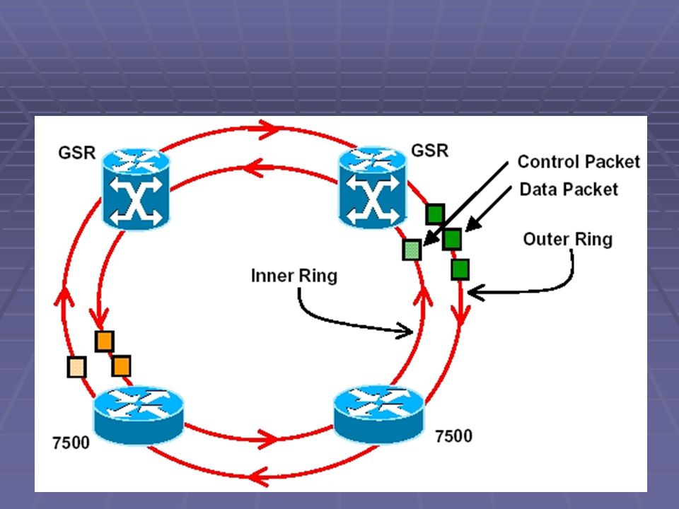
SRP Background Bidirectional Dual Counter-rotation ring “Inner” and “Outer” Rings Both rings are utilized for transporting data and SRP control packets SRP control packets: Topology Discovery Protection Switching Bandwidth Control

12
Spatial Reuse Node C has full bandwidth access to Node D, while Node B to Node A and Node C to Node A are sharing the bandwidth

13
Receive-Side Packet Handling Stripped Received and Stripped Received and Forwarded Forwarded (data packets) Wrapped Pass Through (control packets)
 Wrapped Pass Through (control packets)")
14
SRP Fairness Algorithm (SRP-fa) Global Fairness Each node controls the rate of forwarding packets for upstream or downstream nodes in relations to packets sourced by itself Local Optimization Maximally leverage spatial reuse properties to utilize more than their fair share Scalability Rapidly adapt to changing traffic conditions
 Global Fairness Each node controls the rate of forwarding packets for upstream or downstream nodes in relations to packets sourced by itself Local Optimization Maximally leverage spatial reuse properties to utilize more than their fair share Scalability Rapidly adapt to changing traffic conditions")
15
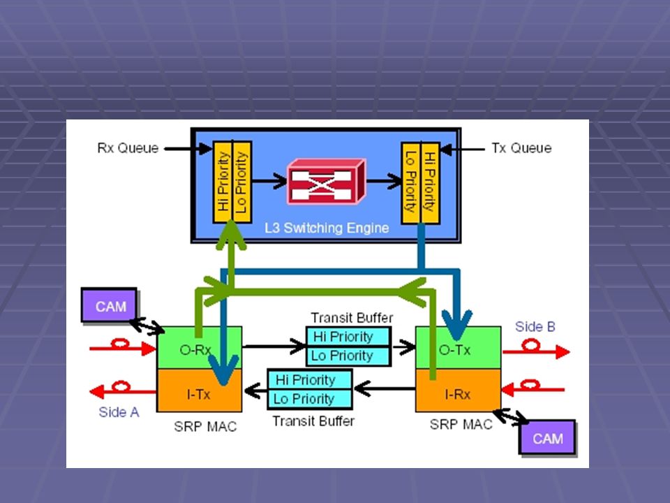
For each node, there are three types of packet: High-Priority Packets Put in High-Priority Transit Buffer Low-Priority Packets Put in Low-Priority Transit Buffer (LPTB) Self-Generated Packets Put in High (Low)-Priority Transmit Queue Packet Priority in Nodes High-Priority Transit Buffer High-Priority Transmit Queue Low-Priority Transit Buffer Low-Priority Transmit Queue
 Self-Generated Packets Put in High (Low)-Priority Transmit Queue Packet Priority in Nodes High-Priority Transit Buffer High-Priority Transmit Queue Low-Priority Transit Buffer Low-Priority Transmit Queue")
17
Packet delivery order High-Priority Forwarded Packets are sent first High-Priority Generated Packets are sent if the LPTB is not full Low-Priority Forwarded Packets are sent with Forward Rate Low-Priority Generated Packets are sent if LPTB is not crossed the low-priority threshold and SRP-fa rules allow it my_usage < allow_usage

18
Updated every clock cycle my_usage (bytes) is increased as the generated low- priority packet inserted in the ring fwd_rate (bytes) is increased as the forwarded low- priority packet inserted in the ring my_usage should be smaller than allow_usage & MAX_USAGE and fwd_rate is larger than my_usage or LPTB is empty, the host is permitted to send its packets
 is increased as the generated low- priority packet inserted in the ring fwd_rate (bytes) is increased as the forwarded low- priority packet inserted in the ring my_usage should be smaller than allow_usage & MAX_USAGE and fwd_rate is larger than my_usage or LPTB is empty, the host is permitted to send its packets")
19
Calculated every DECAY_INTERVAL DECAY_INTERVAL = 8000 bytes for OC-12s/STM-4; 32000 bytes for OC-48s/STM-16 AGECOEFF = 4 LP_MY_USAGE = 512 LP_FWD_RATE = 64 LP_ALLOW = 64 MAX_LINE_RATE = AGECOEFF * DECAY_INTERVAL If LPTB is larger than ½ THRESHOLD, then it is congested If receiving not NULL usage packet, allow_usage is set to usage packet, otherwise, allow_usage is increased 8000 bytes * 8 = 64000 bits = 6.4 Mb OC-12 = 51.84*12 = 622.08 (Mbps) => (6.4) / (622.08) = 0.0103 (sec) 32000 bytes * 8 = 256000 bits = 25.6 Mb OC-48 = 51.84*48 = 2488.32 (Mbps) => (25.6) / (2488.32) = 0.0103 (sec)
 => (6.4) / (622.08) = (sec) bytes * 8 = bits = 25.6 Mb OC-48 = 51.84*48 = (Mbps) => (25.6) / ( ) = (sec)")
20
When congested If lp_my_usage > received_usage (smaller is set to advertise usage packet) advertise usage packet is set to received_usage
 advertise usage packet is set to received_usage")
21
If not congested If received_usage is not NULL Advertise usage packet is set to received_usage Otherwise Advertise usage packet is NULL

23
SRP-fa Procedure Extract usage information from incoming packets Periodically update the allow_usage threshold based on the received fairness value as well as parameter aging Calculate the SRP-fa signaling information to send in the usage field by using the values of the allow_usage, fwd_rate and my_usage parameter. Send fairness message to upstream neighbor

24
SRP-fa Simulation Node 4 starts to send packets to Node 1 via outer ring at 1 second Node 3 starts to send packets to Node 1 via outer ring at 2 second Node 2 starts to send packets to Node 1 via outer ring at 3 second

25
SRP-fa Simulation Node 4 sends traffic at full speed during 1~2 seconds Node 3 wants to send traffic at 2 second, then Node 3 sends a fairness (usage) packet to Node 4 Node 4 slows down its transmitting rate Node 3 starts to send traffic and the bandwidth is shared by Node 3 and Node 4 Node 2 wants to send traffic at 3 second, then Node 2 sends a fairness (usage) packet to Node 3 and Node 4 Node 3 and Node 4 slow down its transmitting rate Node 2 starts to send traffic and the bandwidth is shared by Node 2, Node 3 and Node 4
 packet to Node 4 Node 4 slows down its transmitting rate Node 3 starts to send traffic and the bandwidth is shared by Node 3 and Node 4 Node 2 wants to send traffic at 3 second, then Node 2 sends a fairness (usage) packet to Node 3 and Node 4 Node 3 and Node 4 slow down its transmitting rate Node 2 starts to send traffic and the bandwidth is shared by Node 2, Node 3 and Node 4")
26
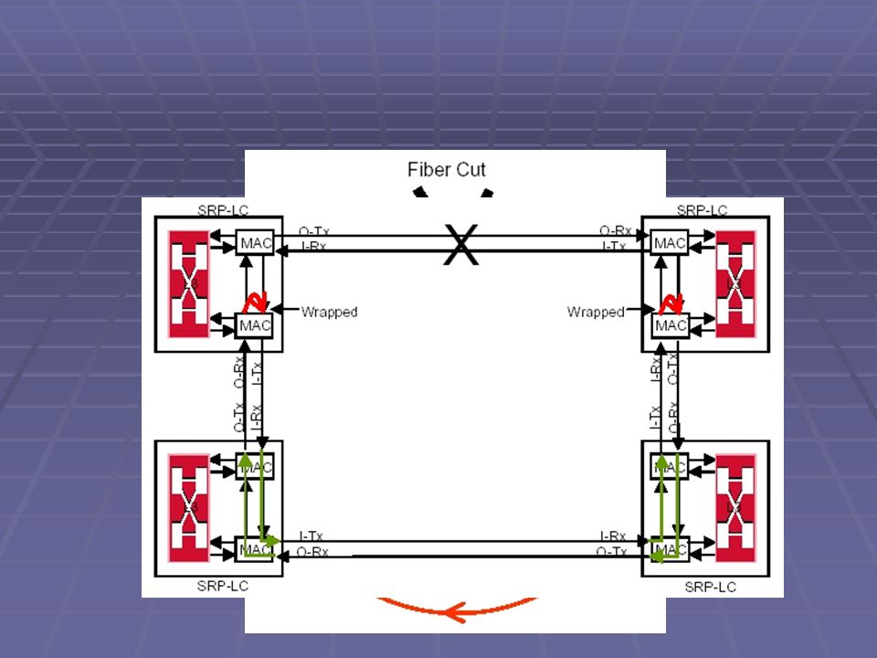
Intelligent Protection Switching (IPS) IPS provides SRP rings with powerful self-healing capabilities that allow them to automatically recover from fiber facility or node failure by wrapping the traffic on the failed span Proactive fault and performance monitoring, and event detection and reporting Signal processing and propagation to communicate information on detected faults and fault clearances Topological knowledge independence Network operator may add or remover nodes from the rings Ring wrapping to by-pass failed fiber facility or nodes while delivering packets to the intended destination Protection switching is transparent to Layer 3 Protection switching event hierarchy Handling of concurrent multiple events Procedures which minimize IPS-related signaling traffic under normal conditions
 IPS provides SRP rings with powerful self-healing capabilities that allow them to automatically recover from fiber facility or node failure by wrapping the traffic on the failed span Proactive fault and performance monitoring, and event detection and reporting Signal processing and propagation to communicate information on detected faults and fault clearances Topological knowledge independence Network operator may add or remover nodes from the rings Ring wrapping to by-pass failed fiber facility or nodes while delivering packets to the intended destination Protection switching is transparent to Layer 3 Protection switching event hierarchy Handling of concurrent multiple events Procedures which minimize IPS-related signaling traffic under normal conditions")
28
IPS Request Type Automatic request Signal Fail (SF) 2 Signal Degrade (SD) 3 Wait-to-Restore (WTR) 5 Manual request Forced Switch (FS) 1 Manual Switch (MS) 4 Path Indicator Short Path IPS Messages: one-hop away Long Path IPS Messages: sent around the ring
 2 Signal Degrade (SD) 3 Wait-to-Restore (WTR) 5 Manual request Forced Switch (FS) 1 Manual Switch (MS) 4 Path Indicator Short Path IPS Messages: one-hop away Long Path IPS Messages: sent around the ring")
29
Thank you

Similar presentations


 Hai Tao.>")


>")

