Download presentation
Presentation is loading. Please wait.

1
Part 1 Structural Modeling Use case modeling
Introduction to UML Part 1 Structural Modeling Use case modeling

2
Overview UML – background Quick tour of a subset of UML
Structural modeling – Class Diagrams Essentials More advanced features Use case modeling - Use Case Diagrams Behavioral Modeling - Event Diagrams, State Diagrams.

3
The Challenge Tijuana “shantytown”:

4
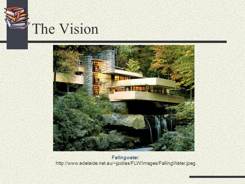
The Vision Fallingwater:
5
Quick Tour The UML is a graphical language for
specifying visualizing constructing documenting the artifacts of software systems Added to the list of OMG adopted technologies in November 1997 as UML 1.1 Most recent minor revision is UML 1.3 (November 1999)
")
6
UML Goals Define an easy-to-learn but semantically rich visual modeling language Unify the Booch, OMT, and Objectory modeling languages Include ideas from other modeling languages Incorporate industry best practices Address contemporary software development issues scale, distribution, concurrency, executability, etc. Provide flexibility for applying different processes Enable model interchange and define repository interfaces

7
OMG UML Contributors Contributors = Original Submitters + RTF1 + RTF2 + … Microsoft ObjecTime Oracle Ptech OAO Technology Solutions Rational Software Reich SAP Softeam Sterling Software Sun Taskon Telelogic Unisys … Aonix Colorado State University Computer Associates Concept Five Data Access EDS Enea Data Hewlett-Packard IBM I-Logix Inline Software Intellicorp Klasse Objecten Lockheed Martin

8
UML The basic building blocks of UML are:
model elements (classes, objects, components, use cases, etc.) relationships (associations, generalization, dependencies, etc.) Depicted via diagrams: class, object diagrams use case diagrams sequence (event) diagram activity diagrams collaboration diagram package diagram deployment diagram
 relationships (associations, generalization, dependencies, etc.) Depicted via diagrams: class, object diagrams. use case diagrams. sequence (event) diagram. activity diagrams. collaboration diagram. package diagram. deployment diagram.")
9
Structural, Use case and Behavioral modeling
Structural model: shows the static structure of the model the entities that exist (e.g., classes, interfaces, components, nodes), their internal structure and relationship to other entities does not include temporal information Class&Object Diagrams (Analysis and Design) Component and Deployment Diagrams (Design and Implem.) does not include interaction (message connections) Use case model -specifies system requirements in OO manner Use case diagram and description Behavioral/interaction model Sequence (event) diagram, Activity diagram State diagram
, their internal structure and relationship to other entities. does not include temporal information. Class&Object Diagrams (Analysis and Design) Component and Deployment Diagrams (Design and Implem.) does not include interaction (message connections) Use case model -specifies system requirements in OO manner. Use case diagram and description. Behavioral/interaction model. Sequence (event) diagram, Activity diagram. State diagram.")
10
Class Diagram and Object Diagram
Shows static structure of concepts Concepts and Classes, Types (interfaces to software components) Relations between them Can be shown on various levels of granularity (example on the next slide)
 Relations between them. Can be shown on various levels of granularity (example on the next slide)")
11
Example: Class specification, 3 levels

12
Classes: method body

13
Generalization

14
Generalization

15
Associations (a.k.a. Instance Connections) and Association Classes
Notice: Multiplicity labels are placed in reverse-order of Coad-Yourdon OOA Associations can be labeled and directed. Job – is an association class. Implies One Job per each Person-Company association. Job * 1..* Company Person employer employee Job salary

16
Aggregation and Composition
Both represent whole-part relationship, but are defined differently by different people Aggregation (white diamond) Composition (black diamond) is a stronger notion: parts do not exists outside of whole, each part belongs to a single whole.
 Composition (black diamond) is a stronger notion: parts do not exists outside of whole, each part belongs to a single whole.")
17
Note directionality (a.k.a. Navigability) of the connection and label.
 of the connection and label.")
18
Many ways of depicting Composition
Window scrollbar [2]: Slider title: Header body: Panel Window 1 1 1 scrollbar 2 title 1 body 1 Slider Header Panel

19
Composition Fig. 3-36, UML Notation Guide

20
Advanced Concepts Qualified associations
Parameterized classes (a.k.a templates) Types and Implementation Classes Interfaces
 Types and Implementation Classes. Interfaces.")
21
Qualified Associations
Account# is the qualifier of Bank-Person association means Unique instance of Account # per each Bank-Person association. Thus, all access to Person in connection to a Bank requires the value of Account #. Bank Account # Person 0..1

22
Parameterized Classes a.k.a. Templates
Example: class Set – represents a collection of objects of a class. That class becomes a parameter to the parameterized class e.g. set of coins, set of students, set of <T> Parameter Parameterized Class T T Set StudentSet Insert(T) Remove(T) “bind” T to Student Unlike with specialization, Class StudentSet cannot add Attributes nor Services
 Remove(T) bind T to Student. Unlike with specialization, Class StudentSet cannot add Attributes nor Services.")
23
Types and Implementation Classes
Type – specifies the behavioral model Implementation Classes defines the implementing data structure and methods for the stereotype HashTable 1 T <<type>> Set T T Insert(T) <<implementatuibClass>> HashTableSet Remove(T) InSet?(T) Insert(T) Remove(T) InSet?(T) SetTableSize(size) realization
 <<implementatuibClass>> HashTableSet. Remove(T) InSet (T) Insert(T) Remove(T) InSet (T) SetTableSize(size) realization.")
24
Interface Classes Interface – a named set of operations that characterize the behavior of an element Interface Classes – similar idea to purely Abstract Classes (no instances), but have no Attributes.Interfaces are realized by implementing them classes
, but have no Attributes.Interfaces are realized by implementing them classes.")
25
Structural Modeling: Summary of Notation

26
Structural Modeling: Summary of Notation
¹ An extension mechanism useful for specifying structural elements.

27
Structural Modeling:Relationships

28
Structural Modeling: Relationships

29
Structural Modeling Tips
Define a “skeleton” (or “backbone”) that can be extended and refined as you learn more about your domain. Focus on using basic constructs well; add advanced constructs and/or notation only as required. Defer implementation concerns until late in the modeling process. Structural diagrams should emphasize a particular aspect of the structural model contain classifiers at the same level of abstraction Large numbers of classifiers should be organized into packages
 that can be extended and refined as you learn more about your domain. Focus on using basic constructs well; add advanced constructs and/or notation only as required. Defer implementation concerns until late in the modeling process. Structural diagrams should. emphasize a particular aspect of the structural model. contain classifiers at the same level of abstraction. Large numbers of classifiers should be organized into packages.")
30
When to model structure
Adopt an opportunistic top-down+bottom-up approach to modeling structure Specify the top-level structure using “architecturally significant” classifiers and model management constructs (packages, models, subsystems; see Tutorial 3) Specify lower-level structure as you discover detail re classifiers and relationships If you understand your domain well you can frequently start with structural modeling; otherwise If you start with use case modeling (as with a use-case driven method) make sure that your structural model is consistent with your use cases If you start with role modeling (as with a collaboration-driven method) make sure that your structural model is consistent with your collaborations
 Specify lower-level structure as you discover detail re classifiers and relationships. If you understand your domain well you can frequently start with structural modeling; otherwise. If you start with use case modeling (as with a use-case driven method) make sure that your structural model is consistent with your use cases. If you start with role modeling (as with a collaboration-driven method) make sure that your structural model is consistent with your collaborations.")
31
Use Case Modeling What is use case modeling? Core concepts
Diagram tour When to model use cases Modeling tips Example: Online HR System

32
Use case modeling use case model: a view of a system that emphasizes the behavior as it appears to outside users. A use case model partitions system functionality into transactions (‘use cases’) that are meaningful to users (‘actors’). Actors are people or other systems
 that are meaningful to users (‘actors’). Actors are people or other systems.")
33
Use Case Modeling: Core Elements

34
Use Case Modeling: Core Relationships
<<extend>>

35
Use Case Modeling: Core Relationships (cont’d)
<<include>>

36
Use Case Diagram Tour Shows use cases, actor and their relationships
Use case internals can be specified by text and/or interaction diagrams Kinds use case diagram use case description

37
Use Case Diagram Fig. 3-44, UML Notation Guide

38
Use Case Relationships

39
Actor Relationships Fig. 3-46, UML Notation Guide

40
Use Case Description: Change Flight Itinerary
Actors: traveler, client account db, airline reservation system Preconditions: Traveler has logged on to the system and selected ‘change flight itinerary’ option Basic course System retrieves traveler’s account and flight itinerary from client account database System asks traveler to select itinerary segment she wants to change; traveler selects itinerary segment. System asks traveler for new departure and destination information; traveler provides information. If flights are available then … System displays transaction summary. Alternative courses If no flights are available then …

41
When to model use cases Model user requirements with use cases.
Model test scenarios with use cases. If you are using a use-case driven method start with use cases and derive your structural and behavioral models from it. If you are not using a use-case driven method make sure that your use cases are consistent with your structural and behavioral models.

42
Use Case Modeling Tips Make sure that each use case describes a significant chunk of system usage that is understandable by both domain experts and programmers When defining use cases in text, use nouns and verbs accurately and consistently to help derive objects and messages for interaction diagrams (see Lecture 2) Factor out common usages that are required by multiple use cases If the usage is required use <<include>> If the base use case is complete and the usage may be optional, consider use <<extend>> A use case diagram should contain only use cases at the same level of abstraction include only actors who are required Large numbers of use cases should be organized into packages (see Lecture 3)
 Factor out common usages that are required by multiple use cases. If the usage is required use <<include>> If the base use case is complete and the usage may be optional, consider use <<extend>> A use case diagram should. contain only use cases at the same level of abstraction. include only actors who are required. Large numbers of use cases should be organized into packages (see Lecture 3)")
43
Example: Online HR System

44
Online HR System: Use Case Relationships

45
Online HR System: Update Benefits Use Case
Actors: employee, employee account db, healthcare plan system, insurance plan system Preconditions: Employee has logged on to the system and selected ‘update benefits’ option Basic course System retrieves employee account from employee account db System asks employee to select medical plan type; include Update Medical Plan. System asks employee to select dental plan type; include Update Dental Plan. … Alternative courses If health plan is not available in the employee’s area the employee is informed and asked to select another plan...

46
Ideas to Take Away UML is effective for modeling large, complex software systems It is simple to learn for most developers, but provides advanced features for expert analysts, designers and architects It can specify systems in an implementation-independent manner 10-20% of the constructs are used 80-90% of the time Structural modeling specifies a skeleton that can be refined and extended with additional structure and behavior Use case modeling specifies the functional requirements of system in an object-oriented manner

47
References OMG UML Specification v. 1.3, OMG doc# ad/06-08-99
available from many urls, including [Kobryn 00] UML 2001: A Standardization Odyssey, Communications of the ACM, Oct [Kobryn 99] Object Modeling with UML: Introduction to UML, Tutorial, available from [Fowler (with Scott)] UML Distilled, Addison-Wesley
] UML Distilled, Addison-Wesley.")
Similar presentations


>")


 – Part One Ku-Yaw Chang Assistant Professor.>")


![1/31 CS 426 Senior Projects Chapter 1: What is UML? Chapter 2: What is UP? [Arlow and Neustadt, 2005] January 22, 2009.](/16/5189061/big_thumb.jpg "1/31 CS 426 Senior Projects Chapter 1: What is UML? Chapter 2: What is UP? [Arlow and Neustadt, 2005] January 22, 2009.>")
