Download presentation
Presentation is loading. Please wait.

1
Magnetic Design Considerations Transformers –Used to step-up or step-down voltages Inductors –Storage during energy transfer –Carries a DC current while supplying current –Need to avoid saturation of the core

2
Transformer Primary Voltage in Terms of Flux

3
Transformer Powers and Efficiency P t = apparent transformer power P i = transformer input power P o = transformer output power η = transformer efficiency

4
Bridge Rectifier Example

5
Analysis Primary voltage V 1 –V 1 = K t fN 1 Φ m (K t = 4.44 for sinusoids) Apparent Power of the transformer –P t = V 1 I 1 + V 2 I 2 For N 1 = N 2 = N and I 1 = I 2 = I –P t = VI = K t fNΦ m I –P t = K t fB m A c NI B m = peak flux density A c = cross-sectional area of the flux path
 Apparent Power of the transformer –P t = V 1 I 1 + V 2 I 2 For N 1 = N 2 = N and I 1 = I 2 = I –P t = VI = K t fNΦ m I –P t = K t fB m A c NI B m = peak flux density A c = cross-sectional area of the flux path")
6
Analysis (continued) Number of Ampere-Turns –NI = K u W a J K u = fill factor (between 4 and 6) W a = window area Area Product –A p = W a A c = P t /(K t fB c K u J) Current Density –J = K j A p x
 Number of Ampere-Turns –NI = K u W a J K u = fill factor (between 4 and 6) W a = window area Area Product –A p = W a A c = P t /(K t fB c K u J) Current Density –J = K j A p x")
7
Core Configuration Constants

8
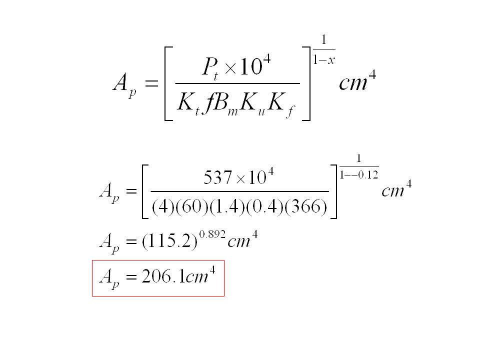
Area Product A p

9
Core Area for Various Core Types WaWa

10
Design of a Transformer Example 14.6 f = 60HzV 1 = 120V 60-Hz square-waveV o = 40V, I o = 6.5A Assume η = 95% and window factor K u = 0.4 Use E-core

11
Solution K t = 4 for a square wave Output Power –P o = V o I o = (40V)(6.5A) = 260 W Total Power –P t = P o (1/η + 1) = 260(1/0.95 + 1) = 533.7 W Check Table 14.1 for E-core –K j = 366x = -0.14 Choose B m = 1.4
(6.5A) = 260 W Total Power –P t = P o (1/η + 1) = 260(1/ ) = W Check Table 14.1 for E-core –K j = 366x = Choose B m = 1.4")
13
Choosing the E-core Choose a type core2-138EI –A p = 223.39 cm 4 –core weight, W t = 3.901 kg –core area, A c = 24.4 cm 2 –mean length of a turn, l mt = 27.7 cm

14
Calculate the number of primary turns

15
Calculate the number of secondary turns

16
Calculate the primary current

17
Calculate the primary wire size Check wire-size Table B.2 in Appendix B AWG #16 has cross-sectional area of 13.07x10 -3 cm 2

18
Calculate the primary copper loss

19
Calculate the secondary wire size Check wire-size Table B.2 in Appendix B AWG #11 has cross-sectional area of 41.68x10 -3 cm 2

20
Calculate the secondary copper loss

21
Push-Pull

22
Half Bridge with Center-Tap Transformer

23
Cores With 2 Permeability Regions

Similar presentations


 in the core : B max (T or Wb/m 2 ) Core losses Saturation Peal Current density in the.>")


 a voltage by passing a wire through a magnetic.>")

