Download presentation
Presentation is loading. Please wait.

1
Parameter Scaling Most filter designs are given in a normalised form, i.e. for a cut-off frequency of 1 rad/s. To transform for an arbitrary frequency, the component values must be scaled.

2
Design Example – Low Pass Filter

3
Normalised Un-normalised

4
Sensitivity When designing high-order filters (e.g. six or more poles), damping ratios of individual sections can be very low. The actual damping ratio of the Sallen and Key filter is sensitive to the open loop gain of the op-amp. This sensitivity is especially notable when the cut-off frequency is high (implying the open loop gain is low). Detailed sensitivity calculations are required to quantify this effect…(ref. Sedra & Smith)
, damping ratios of individual sections can be very low. The actual damping ratio of the Sallen and Key filter is sensitive to the open loop gain of the op-amp. This sensitivity is especially notable when the cut-off frequency is high (implying the open loop gain is low). Detailed sensitivity calculations are required to quantify this effect…(ref. Sedra & Smith).")
5
Sensitivity Example 100100010000 0.01 0.1 1 10 Frequency [rad/s] Gain
![Sensitivity Example Frequency [rad/s] Gain](http://images.slideplayer.com/16/4996318/slides/slide_5.jpg "Sensitivity Example Frequency [rad/s] Gain")
6
Overcoming Sensitivity Problems In high order filters, the compounded errors due to the sensitivity of the Sallen & Key configuration could be significant. Solutions: Use better tolerance components. Use a different configuration Component Simulation Operational Simulation

7
Component Simulation Filter design by component simulation can be broken down into two stages: Design a passive LCR network that realises the desired transfer function. Replace all the inductors with equivalent active networks (impedance convertors). E.g. Passive high pass filter
. E.g. Passive high pass filter.")
8
Impedance Convertors Impedance Convertor Voltage controls voltage. Current controls current. Conversion works in either direction – bilateral.

9
Impedance Conversion Impedance Convertor

10
Using Impedance Convertors The impedance appears to be multiplied by the convertor circuit. Several types of convertor: Positive Impedance Convertor (PIC) : K is real and positive. Negative Impedance Convertor (NIC) : K is real and negative. Generalised Impedance Convertor (GIC) : K is complex and may be frequency dependent. For example, Z L = a resistance, R K = j Z IN = j R i.e. input looks like an inductance.
 : K is real and positive. Negative Impedance Convertor (NIC) : K is real and negative. Generalised Impedance Convertor (GIC) : K is complex and may be frequency dependent. For example, Z L = a resistance, R K = j Z IN = j R i.e. input looks like an inductance..")
11
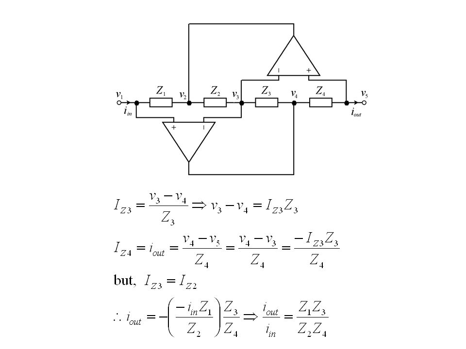
Generalised Impedance Convertor Op-amp analysis rules:

12
Consider currents flowing from left to right:

14
Loaded GIC 0V

15
Simulated Grounded Inductor The input appears to be an inductance of CR 2 Henrys.

16
Five Pole High Pass Filter Example

17
Summary The Sallen & Key second order filter configuration is highly sensitive to component tolerances. The resulting errors are particularly problematic for high order filters. Component simulation is an alternative filter design technique. It simply replaces inductors in a passive filter by active equivalent circuits. The GIC configuration can simulate a grounded inductor using two op-amps.

Similar presentations


. Maximum Power Transfer Choose an RL in order to maximize power delivered to RL.>")
 transistors start to manifest.>")


>")

 can simulate a grounded inductor. This is fine for high-pass filters. The inductors in.>")


 They.>")


 Before 2001, more and more material.>")