Download presentation
Presentation is loading. Please wait.

1
The Motor Vehicle Problem
朱信 Hsin Chu Professor Dept. of Environmental Eng. National Cheng Kung University

2
1. An Overview of the Problem of Air Pollution from Motor Vehicles
The first gasoline-powered automobiles appeared in 1886. By 1900 world production was only about 20,000 vehicles per year, compared to about 30 million in 1999. Although any one car consumes little fuel and emits small amounts of pollutants, together the roughly 500 million of them in the world consume large amounts of fuel and emit large amounts of pollutants.

3
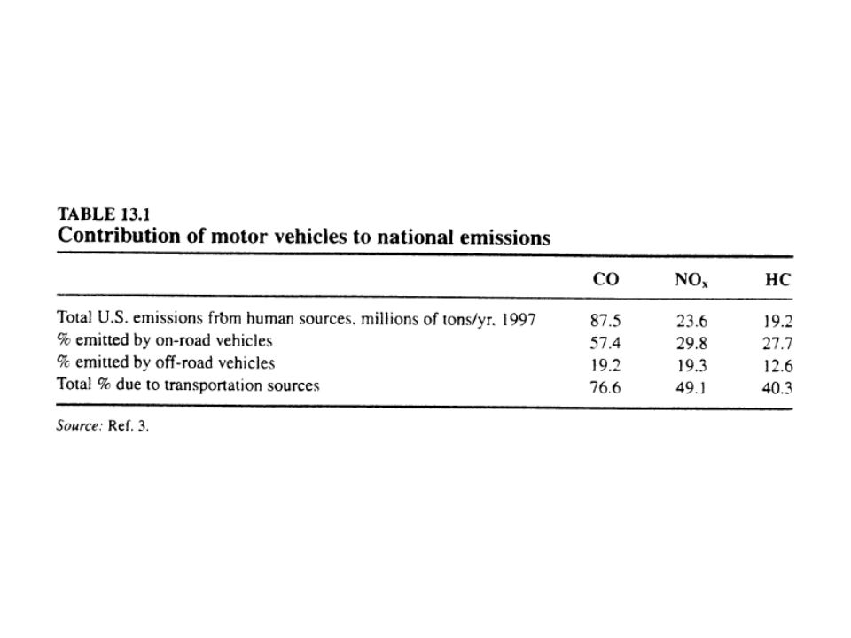
1.1 Emissions There are about 123 million autos in the US and about 70 million trucks. Next slide (Table 13.1) Motor vehicles are the source of three-fouths of the US emissions of CO, and 40 to 50% of the US emissions of HC and NOX.
 Motor vehicles are the source of three-fouths of the US emissions of CO, and 40 to 50% of the US emissions of HC and NOX.")
5
“Off-road vehicles” in Table 13
“Off-road vehicles” in Table 13.1 include aircraft, railroads, boats, construction equipment, and farm equipment. From Table 13.1, autos and light trucks contribute much more to the US emissions than do these other sources.

6
1.2 The Regulatory History of Motor Vehicle Air Pollution Control
Motor vehicles did not attract much attention as air pollution sources until about 1950. As coal combustion sources were controlled, and as natural gas replaced coal as the principal urban heating fuel in the US, a new type of air pollution was discovered in Los Angeles.

7
A type of eye and nose-irritating air pollutant, later named smog, occurred there, mostly in the summer. Professor A. J. Haagen-Smit demonstrated the eye-irritating materials were largely formed from emissions from autos.

8
California began to regulate emissions from autos in 1963.
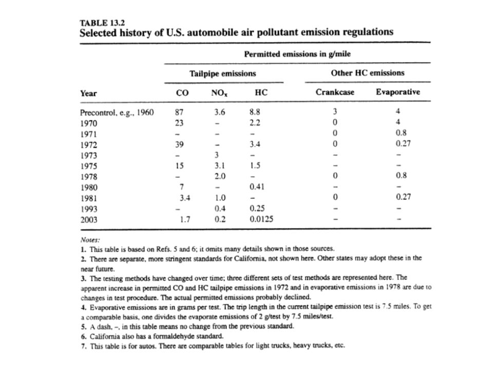
In the clean Air Act of 1970 US Congress began federal regulation of autos, requiring stricter rules for any states that already had state rules (only California), but also requiring fairly strict rules for the rest of the country. The history of these regulations is shown in Table 13.2 (next slide).
, but also requiring fairly strict rules for the rest of the country. The history of these regulations is shown in Table 13.2 (next slide).")
10
2. The Internal Combustion (IC) Engine
External combustion engines were developed before internal combustion engines. James Watt’s 1776 steam engine was the first general-purpose heat engine that converted heat from combustion to a steady flow of power to a rotating shaft.

11
For 100 years steam engines, with combustion in a boiler external to the power –producing part of the engine, were the only combustion engines. These steam engines launched a giant technological expansion, which, among other things, led to the development of much better machine tools. The improved machine tools made it possible to build the first IC engines.

12
The first commercially successful IC engines (combustion inside the power-producing parts) were those of Otto and Langen about 1876. For a given power output these engines were substantially smaller and lighter than external combustion engines and had a higher thermal efficiency (lower fuel consumption).
.")
13
Those features made them the natural choice for motor vehicles.
The steam engine held on in railroad locomotives until the 1950s, when the major cost savings brought by diesel engines led to its replacement.

14
2.1 The Four-Stroke IC Gasoline Engine
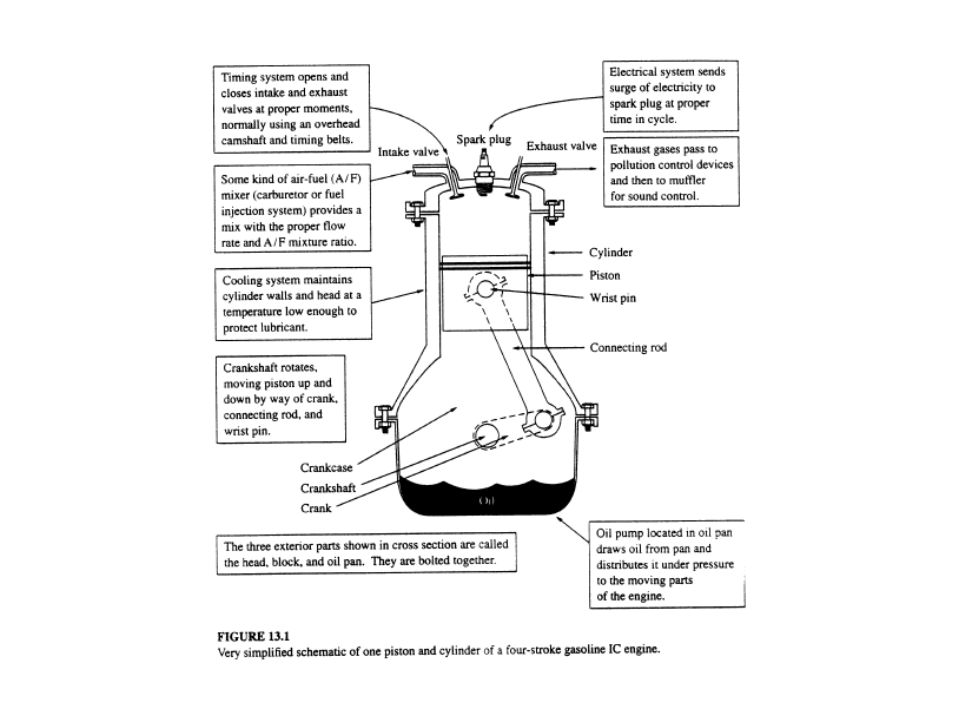
The four-stroke IC gasoline engine has been the power source for most of the autos and small trucks ever built. Next slide (Fig. 13.1) A cross-sectional view of a typical auto engine.
 A cross-sectional view of a typical auto engine.")
16
Most auto engines have four such piston and cylinders, some have six or eight.
To begin a cycle, with the piston at the top (top dead center, TDC) during the first stroke the piston moves downward while the intake value is open, so that an air-fuel mixture is sucked into the combustion chamber (the space within the cylinder, above the piston).
 during the first stroke the piston moves downward while the intake value is open, so that an air-fuel mixture is sucked into the combustion chamber (the space within the cylinder, above the piston).")
17
When the piston is at the bottom (bottom dead center, BDC), the intake valve closes, ending the intake stroke. As the piston rises again to the top during the compression stroke, both valves are closed, so that the air-fuel mixture is compressed. Near the top of that stroke the spark plug fires, igniting the air-fuel mixture.

18
In its next downward travel, the power stroke, the piston is driven by the high-pressure combustion gases, which do the actual work of the engine. At the bottom of the piston travel, the exhaust valve opens, and on its next upward travel the piston pushes the burned gases out into the exhaust system.

19
The cycle is named for its four strokes-intake, compression, power, and exhaust.
The spark plug fires every second upward travel of the piston. Power is produced only during the power stroke. Each of the other three strokes consumes power.

20
2.2 Pollutant Formation The principal pollutants emitted from simple gasoline-powered IC engines are carbon monoxide, hydrocarbons, and nitrogen oxides. Auto engines produce more of them per unit of fuel burned than other combustion processes principally for the following reasons:

21
Auto engines are often oxygen deficient, which most other combustion systems are not. → CO, HC
Auto engines preheat their air-fuel mixtures, which most combustion systems do not. → NOX

22
Auto engines have unsteady combustion, in which each flame lasts about s. Almost all other combustion systems have steady flames that stand still while the materials burned pass through them. → CO, HC Auto engines have flames that directly contact cooled surfaces, which is not common in other combustion systems. → HC

23
2.2.1 Carbon Monoxide, CO In automobile engines we often have less than stoichiometric air. Let the excess air ratio E be negative values or it is much easier to use the oxygen deficit z. For any hydrocarbon fuel with formula CxHy: If there is less than stoichiometric oxygen, we can write:

24
All gasoline are mixtures of many components, but they can be characterized as having an approximate average formula CxHy, where for a typical gasoline x is about 8 and y is about 17. Gasoline manufacturers change these values from one location to another and with season of the year (smaller values in winter and in cold climates than in summer and warm climates).
.")
25
For complete combustion (E = z = 0) of this fuel, the equations is:
If there is not enough oxygen to complete the reaction, then the combustion products will contain CO, H2 and unburned hydrocarbons. At combustion temperatures the most common of these products of incomplete combustion is CO.

26
If we assume that an oxygen deficit of z mols per mol of fuel is fed, and if we assume that all of the oxygen deficit causes CO formation, we can rewrite Eq. (1) as: Each mol of oxygen from air brings with it (0.79/0.21 = 3.76) mols of nitrogen, so that the total mols of combustion products will be:
 mols of nitrogen, so that the total mols of combustion products will be:")
27
The mol fraction of CO will be:
Example 1: Calculate the expected CO mol fraction for combustion of a gasoline with x = 8, y = 17, and with the air supplied being 90 percent of that required for complete combustion.

28
Solution: Therefore, and

29
2.2.2 Air-Fuel Ratio (A/F), Equivalence Ratio (Ø)
Example 2: Calculate A/F and Ø for Example 1. Solution: The A/F is always stated in weight terms in the IC literature (normally lb/lb in the US). In general it is written as:
. In general it is written as:")
30
For this example we have
The equivalence ratio is defined as: The normalized A/F ratio λ=1/Ø = 0.9.

31
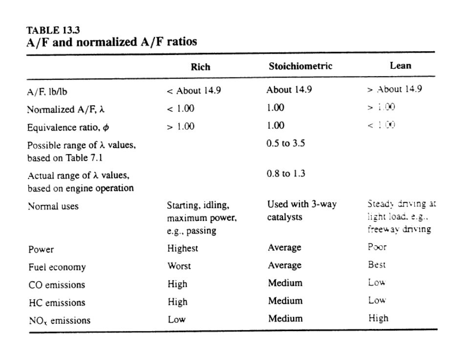
Table 13.3 (next slide) shows the A/F ratios that actually occur in IC engines.
 shows the A/F ratios that actually occur in IC engines.")
33
From Table 13.3, an IC engine would operate satisfactorily for any normalized A/F ratio between 0.5 and 3.5. However, based on experience with actual engines the operable range is from about 0.8 to 1.3. The smaller operable range is mostly due to the large heat losses from the small amount of combustible mixture in the cylinder to the surrounding cooled cylinder walls and head.

34
For steady operation at most driving speeds, the best fuel economy occurs at a λ of about 1.2.
For acceleration or hill climbing the requirement is not best fuel economy but maximum power output, which is found at λ≒0.95. Most engines idle more smoothly at values between 0.90 and (At low speeds there is more time for heat losses to put the flame out.)
")
35
Cold starting poses a special problem for IC engines.
When the engine is cold the exhaust heat is not available, and the temperature in the compressed mixture is so low that much of the liquid fuel is not vaporized. Only the most volatile parts of the fuel will be vaporized under this condition.

36
To make λ, based on the vaporized part of the fuel, be low enough for the engine to start, one must put more total fuel into the air-fuel mixture. In carburetor autos, this excess fuel is added by a choke. This was operated by hand on older cars and is now operated by thermostatic or electronic sensors. Fuel injection engines regulate the amount of fuel injected, taking the same variables into account.

37
2.2.3 Hydrocarbons (HC) At all values of λ one measures unburned HC in the exhaust gases of gasoline IC engines. Most of these are the result of flame quenching.

38
IC engines must have some kind of lubrication where the piston slides up and down in the cylinder.
In auto engines this is provided by the motor oil, which is pumped from a sump at the bottom of the crankcase through holes drilled or cast in the block, bearings, crankshaft, connecting rods, wrist pins, and cylinders to holes on the side of the piston.

39
The piston rings, which are the actual sliding surface between piston and cylinder, ride on this oil film. Normal hydrocarbon lubricants cannot stand temperatures much higher than about F ( C) for long periods.
 for long periods.")
40
The principal purpose of the cooling system of an auto engine is to keep the temperature of the lubricant film between the piston rings and the cylinder wall at or below the temperature. Heavily loaded engines, in trucks or autos that pull trailers, have separate radiators to cool the oil.

41
If the temperature becomes significantly higher than that, the lubricants decompose, leaving behind solid carbon residues that cause the engine to seize. An engine operated without its cooling system is destroyed in a few minutes.

42
Research engines have been built that use solid lubricants (MoS2) that can stand very high temperatures. These engines have no cooling system and operate at temperatures comparable to the melting point of steel. They have excellent fuel economies but very difficult materials-engineering problems.

43
The cooling of the cylinder walls and head makes them cold enough that in a narrow quench zone adjacent to them the flame goes out, and the hydrocarbons in that part of the air-fuel mixture are not burned up. Example 3: Estimate the hydrocarbon concentration to be expected in the exhaust gas from an engine with a piston diameter of 6 cm, a stroke of 5 cm, and a quench zone thickness of 0.2 mm at λ=1.

44
Solution: We assume that all of the surface of the cylinder and the head has a quench zone. The top of the piston is not cooled and does not apparently play a significant role in flame quenching.

45
The ratio of the volume of the quench zone to the volume of the combustion chamber with diameter D, piston travel L, and quench zone thickness t (assuming a flat head) is:
 is:")
46
Thus we would expect 1.7% of the total hydrocarbons in the fuel to appear in the exhaust.
From Eq.(2), Total mol of combustion products =
, Total mol of combustion products =")
47
mol fraction of unburned fuel in exhaust = yunburned
The calculation shows that we would expect a higher hydrocarbon concentration in the exhaust from a small engine than a large one, which is observed.

48
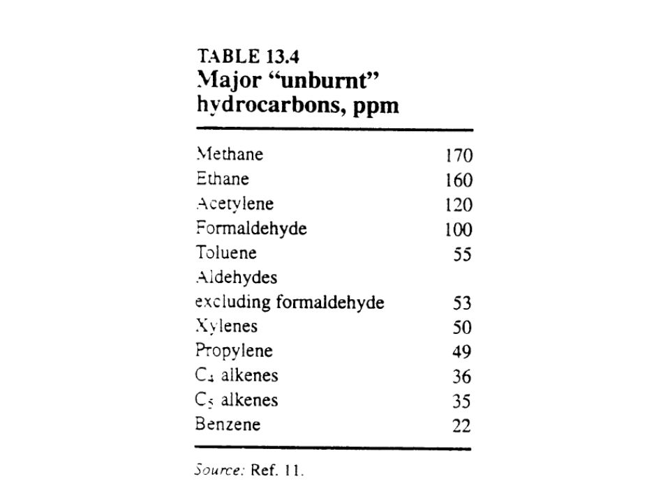
This example assumes that the hydrocarbons in the exhaust have the same chemical composition as those in the fuel. Next slide (Table 13.4) Typical composition of hydrocarbons in untreated auto exhaust.
 Typical composition of hydrocarbons in untreated auto exhaust.")
50
The methane, ethane, acetylene, propylene, formaldehyde, and other aldehydes were not present in the fuel and must have been formed by incomplete combustion, mostly in the quench zone. The benzene, toluene, and xylenes were present in the fuel. They are the gosoline components with the slowest burning velocities, and hence the highest probability of passing, unburned, into the exhaust.

51
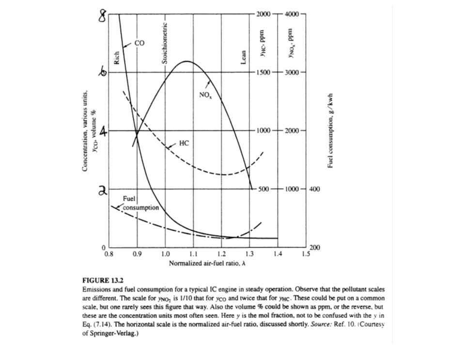
The calculation in Example 3 suggests that the percent hydrocarbon in the vehicle exhaust is independent of air-fuel ratio. Next slide (Fig. 13.2) The typical emissions of NOX, CO and HC from automobile engines as a function of λ .
 The typical emissions of NOX, CO and HC from automobile engines as a function of λ .")
53
From Fig. 13. 2, the CO concentration does not become zero at λ>1
From Fig. 13.2, the CO concentration does not become zero at λ>1.0 but rather continues at some low value, even when there is plenty of excess air in the exhaust gas. At the high temperatures of the flame the reaction that actually consumes CO: is an equilibrium reaction that does not go to completion.

54
As the temperature is lowered toward the exhaust temperature, the equilibrium shifts strongly to the right, but the reaction becomes very slow below a temperature of 2,200 K. Therefore, some of the CO found in the exhaust is due to the noncompletion of this reaction even though adequate oxygen is present.

55
In conclusion, we can say that the CO consists of “oxygen deficit” CO and “incomplete reaction” CO, with the latter being pratically independent of λ. The HC consists of “oxygen deficit” HC and “quench zone” HC, with the “quench zone” amount being about the same at all values of λ. At λ=0.9 we would expect about 4% CO and about 0.1% HC.

56
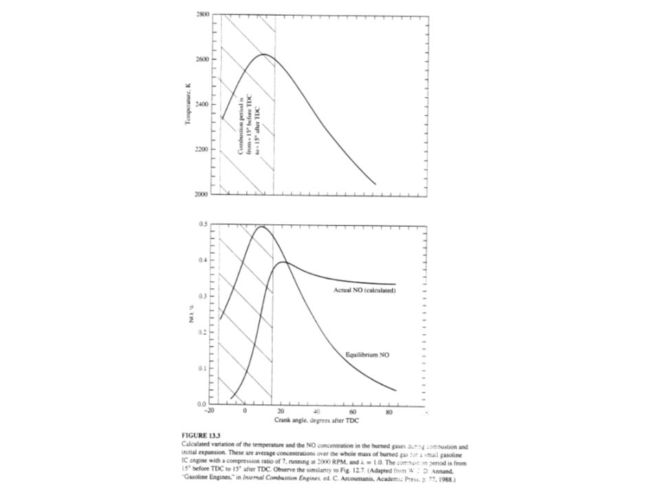
2.2.4 NOX Peak temperatures in an auto engine are of the order of 2,700 K, whereat NO is formed from N2 and O2. Next slide (Fig. 13.3) The calculated temperature and NO concentration history for a typical single combustion in an IC engine.
 The calculated temperature and NO concentration history for a typical single combustion in an IC engine.")
58
Example 4: For the example shown in Fig. 13
Example 4: For the example shown in Fig estimate the temperature before the beginning of combustion, the temperature in the burned gas just after combustion begins, and the temperature in the burned gas at the end of combustion. Solution: The figure shows that combustion begins about 15 degrees before TDC and continues until about 15 degrees after TDC.

59
At 15 degrees before TDC the piston has traveled about 98% of its travel from BDC, so we can safely ignore further piston travel and assume that the gas in the cylinder has been compressed by the stated compression ratio of 7. From standard thermodynamics texts for reversible adiabatic compression, we find:

60
Taking common values of T1 and cP, we write:
The temperature rise during the first part of the buring process, which is assumed to be adiabatic and to occur at constant pressure, is given by:

61
For a typical gasoline △Hcombustion is about 19,020 Btu/lbm and cP, combustion products is about 0.33 Btu/lbm/0F, so that This calculation overstates the temperature increase because it assumes that the whole combustion chamber is filled with air-fuel mixture.

62
In Fig. 13.1, we see that when the exhaust valve closes at the top of the exhaust stroke, the combustion chamber will contain a substantial amount of exhaust gas. The incoming air-fuel mixture mixes with this residual exhaust gas.

63
Measurements indicate that the residual exhaust gas is about 15% of the total charge to the cylinder. Thus the heat released per pound of total gases in the combustion chamber will be about 85% of that just computed, and the temperature rise 85% of that computed above, or △T = 3,0850F = 1,714K.

64
Adding this temperature increase to the initial temperature, we would find a temperature of ,085 = 3,7990F = 4,2390R = 2,355K, which is practically the value shown at 150 before TDC in Fig In addition, at peak temperature the combustion reactions are not driven completely to the right. We would expect some unreacted oxygen and hydrocarbons to be present at equilibrium, thus reducing the peak temperature slightly.

65
We computed the initial temperature rise by assuming the first part of the combustion occurred at constant pressure. This assumption is plausible because, as the first part (near the spark plug) burns, it expands and pushes away the remaining gas. But later, when the remaining gas burns, it also expands and hence compresses the gas that burned first so that it undergoes combustion at practically constant pressure, followed by an adiabatic compression.
 burns, it expands and pushes away the remaining gas. But later, when the remaining gas burns, it also expands and hence compresses the gas that burned first so that it undergoes combustion at practically constant pressure, followed by an adiabatic compression.")
66
At the end of the combustion process the gas temperature in the combustion chamber will not be at a uniform temperature; the first part to burn will be hottest. But if we wish to compute the average temperature we can proceed by assuming that the whole combustion process occurs at constant volume, for which we can write:

67
cV, combustion products for gasoline combustion is typically about 0
cV, combustion products for gasoline combustion is typically about 0.26 Btu/lbm/0F, so that for the overall combustion at constant volume we would compute

68
This shows that The values from Fig are The differences between these values are due to heat losses from the combustion gases and to the work of expansion done by the gases on the piston.

69
The equilibrium NO curve in Fig. 13. 3
The equilibrium NO curve in Fig corresponds to the thermal NO values calculated by the zeldovich mechanism. The actual curve suggests that the rate of NO formation is negligible until the temperature reaches about 2,400 K.

70
The NO concentration rises rapidly toward the equilibrium value, crossing it at about 22 degrees after TDC. From then on the concentration is higher than the equilibrium concentration in the rapidly cooling gas, so the concentration falls. When the gas temperature reaches about 2,300 K the reaction rate becomes negligible, and the NO concentration is “frozen” at a value above the equilibrium value.

71
The combustion period shown corresponds to about 30o of crack angle, or 1/12 of a revolution, and the time of combustion to about 2.5 ms. There is very little nitrogen in gasoline, so the amount of fuel NO is generally negligible.

72
3. Tailpipe Emissions Table 13.2 shows that all the CO and NOX emissions and about half the HC emissions are tailpipe emissions. The possibilities for dealing with these are discussed next. The cheapest and simplest approach is to change what goes on in the combustion process, to minimize the formation of pollutants. The first four alternatives discussed below do that. The remaining four require some change outside the combustion process.

73
3.1 Lean Operation From Fig it is clear that lean combustion greatly reduces CO and HC emissions compared to rich combustion. Before the 1970s mechanics regularly changed the factory carburetor settings to make the combustion richer. Their customers liked the car’s smooth performance, but these changes greatly increased emissions and lost fuel economy.

74
3.2 Exhaust Gas Recirculation (EGR)
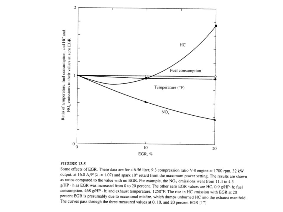
Starting in the 1970s and continuing in many current engines that production of NOX was reduced by EGR, in which the incoming combustion air is diluted with up to 20% exhaust gas. EGR reduces the peak flame temperatures and the O2 content of the burned gas; both of these effects lower the NOX formation.

75
EGR reduces the power output of the engine.
At extremely lean operation EGR can lead to misfire and thus increased HC emissions. Next slide (Fig. 13.5) The effect of EGR
 The effect of EGR.")
77
3.3 Reduce Flame Quenching
Most of the HC and CO are formed by wall quenching of the flame. Various techniques have been used to minimize this. The most obvious is to make the combustion chamber more nearly spherical, thus reducing the surface per unit volume. Reducing the sizes of the crevices associated with the head gasket, spark plug gasket, and piston rings also contributes to reduce flame quenching.

78
Raising the temperature of the cylinder wall and head lowers the thickness of the quench zone.
This was one of the reasons for switching the auto coolant from water in summer and ethylene glycol in winter to a year-round mixture of water and ethylene glycol. Diesel engines place the fuel in the middle of the cylinder and they have much lower CO and HC emissions than conventional auto engines.

79
3.4 Speed the Warmup Much if not most of the CO and HC emissions of a typical driving cycle occur in the first minute or two while the engine is cold. Most engines measure the temperature of both the underhood air and the engine coolant.

80
When these are cold the engine uses valves to draw air through a shroud over the exhaust manifold into the engine air intake to speed the warmup. Some engines use electric heaters located between the carburetor and the engine to warm the air-fuel mix during this cold start period.

81
3.5 Catalytically Treat the Combustion Products
Most auto manufacturers have concluded that they cannot meet current and future emission standards by engine modifications alone. Instead, they have concluded that the most satisfactory solution is to modify the engine so that it produces the right mix of pollutants and then treat that mix catalytically to meet the emission standards.

82
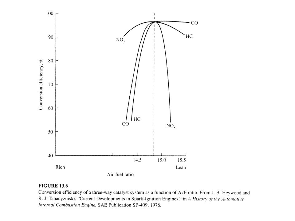
The first attempts used two catalysts, but since then auto manufacturers have developed the “three-way catalyst” that promotes the following reaction: This reaction requires very close control of the ratio of oxidizing agent (NO) to reducing agents (CO + HC) (Fig. 13.6, next slide).
 to reducing agents (CO + HC) (Fig. 13.6, next slide).")
84
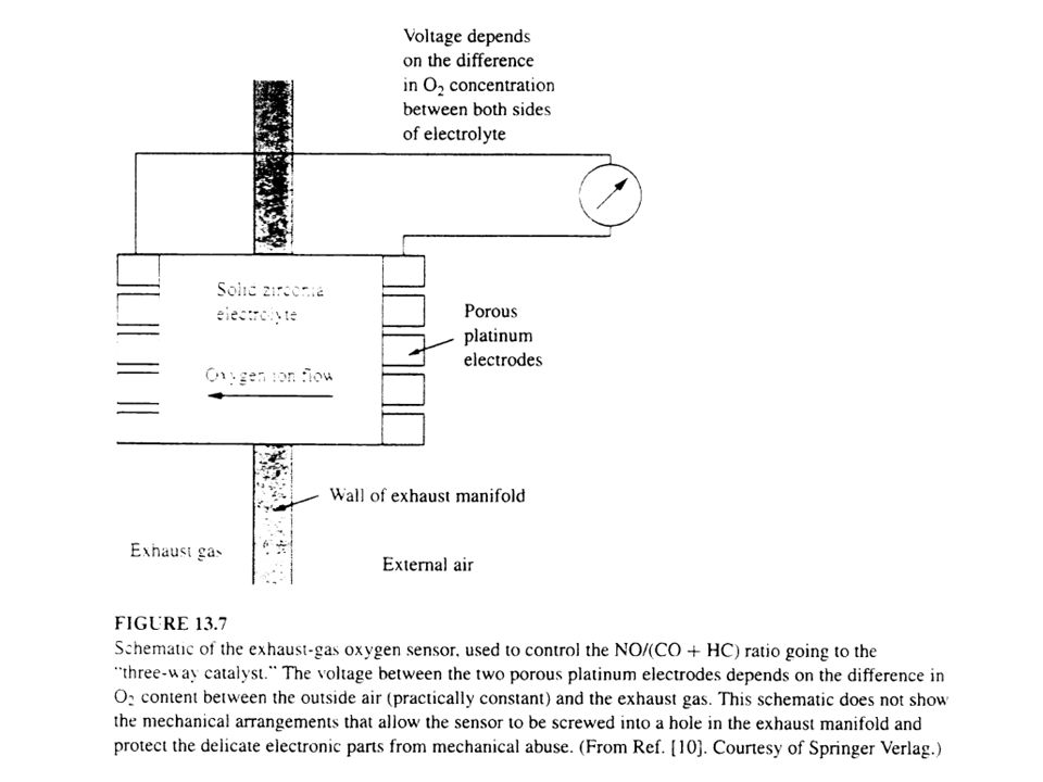
The key to doing this successfully was the development of the doped zirconium dioxide oxygen sensor, shown in Fig (next slide). Using the measured value of the exhaust gas oxygen content, the engine computer can control the A/F ratio to stay within the ±0.05 tolerance (λ tolerance of ±0.003) needed to stay at the top of the curves in Fig
 needed to stay at the top of the curves in Fig")
86
The typical automobile exhaust gas catalyst is a (5:1) mix of platinum or palladium with rhodium, supported on an Al2O3 layer that is deposited on a cheaper ceramic base. The typical “light off” temperature is about 350℃. The catalyst should cause the small amount of S in the gasoline to exhaust as SO2 rather than the much smellier H2S, but not oxidize the SO2 to the more toxic SO3.

87
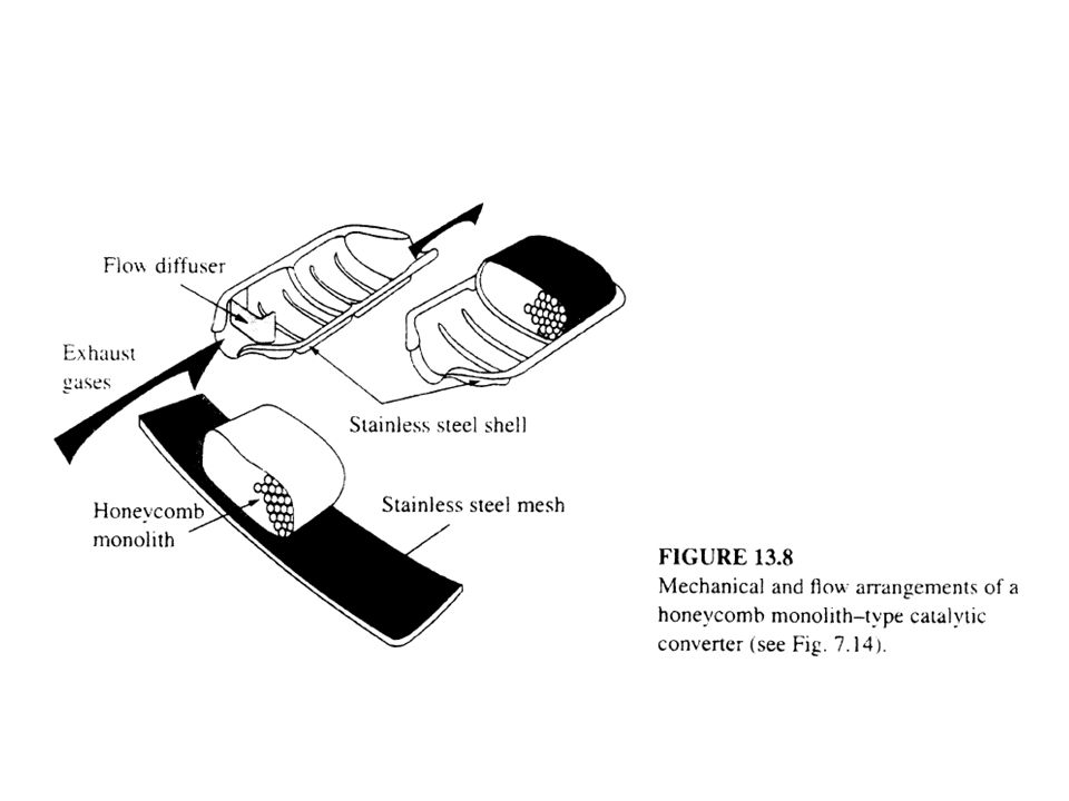
A typical modern auto catalyst has a volume of about one liter and a noble metal content of about 1.5 g. Next slide (Fig. 13.8) The most common arrangement uses a single structure called a honeycomb monolith. Each channel is about 1/20 of an inch wide (400-1,200 cells per in2) and about a foot long. The channel can be hexagonal, square, or triangular; most are square.
 The most common arrangement uses a single structure called a honeycomb monolith. Each channel is about 1/20 of an inch wide (400-1,200 cells per in2) and about a foot long. The channel can be hexagonal, square, or triangular; most are square.")
89
3.6 Change the Fuel The requirements for the fuel for an IC spark ignition engine are as follows: (1) high heating value so that the vehicle will have adequate range between refuelings, without carrying an excessive fuel weight; (2) a high fuel density so that the fuel storage container will be of acceptable size;
 high heating value so that the vehicle will have adequate range between refuelings, without carrying an excessive fuel weight; (2) a high fuel density so that the fuel storage container will be of acceptable size;")
90
(3) easily handled, normally as a liquid at ambient temperatures; (4) good antiknock properties; (5) ability to vaporize in air-fuel system (adequate volatility); (6) other miscellaneous properties, like good storage stability, limit toxicity, etc.
 easily handled, normally as a liquid at ambient temperatures; (4) good antiknock properties; (5) ability to vaporize in air-fuel system (adequate volatility); (6) other miscellaneous properties, like good storage stability, limit toxicity, etc.")
91
Antiknock properties are a very important part of this list.
Returning to Fig. 13.1, we see that the combustible mixture is ignited by the spark plug, which is normally located at or near the middle of the top of the combustion chamber. The flame starts there and spreads out through the chamber.

92
The burned gases have a much higher volume than they had as unburned gases, so they expand and compress the unburned gas. As a result the temperature of the unburned gases rises before the flame reaches them (The propagation speed of the pressure increase is much faster than the speed of the flame front.).
.")
93
If the unburned gas is heated to its autoignition temperature before the flame front reaches it, it will spontaneously ignite, producing a loud knock. It was apparent early in the history of the automobile that raising the compression ratio-that is, (the volume contained at BDC)/(the volume contained at TDC)- increased the efficiency of the engines but also increased their tendency to knock.
/(the volume contained at TDC)- increased the efficiency of the engines but also increased their tendency to knock.")
94
Early engines has compression ratios of about 4, most current auto engines have compression ratio of 8 to 10, and diesel engines have compression ratios of about 16 to 20. In diesel engines the fuel and air are not premixed; fuel is sprayed into the chamber near TDC. In that case the hot gases ignite the fuel without a spark plug.

95
Diesel engines would have a terrible knock problem if the fuel and air were premixed, but they have no problem if the fuel is added slowly and if it burns as it is added. Different families of hydrocarbons have different resistances to knock.

96
Straight-chain hydrocarbons are the worst, highly branched paraffins the best, olefins better than corresponding paraffins, and aromatics almost as good as highly branched paraffins. The order of quality is just the reverse for diesel fuels. Fuels are rated by their octane number, which is equivalent to the percent isooctane (2,2,3-trimethylpentane) in a blend of isooctane and n-heptane that has the same antiknock properties.
 in a blend of isooctane and n-heptane that has the same antiknock properties.")
97
This is equivalent to assigning an octane number of 100 to isooctane and of zero to n-heptane, and assuming linearity of octane number on blending of these two. Typical motor fuels in Taiwan have octane numbers in the range of

98
Fuels for piston air craft engines have octane number over 100; these are expensive, but they allow a higher compression ratio and thus better fuel economy and longer range. One can improve the octane number with additives. The most successful has been tetraethyl lead (TEL).
.")
99
When it is added to gasoline at the ratio of up to 0
When it is added to gasoline at the ratio of up to 0.1% by weight, it can increase the octane number by up to 6. Unfortunately, although lead leaves the combustion chamber as a gas it forms fine particles on cooling. These deactivate automotive emission catalysts and increase the lead content of the atmosphere.

100
Natural gas meets all the requirements just listed except that of easy storage on the vehicle (2,500 psia). Other gaseous fuels, e.g. CO or H2, can be used in slightly modified automobile engines if a suitable storage system can be worked out.

101
Commercial propane, sometimes called LPG (liquefied petroleum gas), is a mixture that is typically 90+ percent propane. Its vapor pressure at 1000F is about 200 psig. It is a perfectly satisfactory fuel for gasoline engines.

102
The two lowest molecular weight alcohols-methanol, CH3OH, and ethanol, C2H5OH - can be used in slightly modified gasoline engines (Brazil: sugarcane) All of the fuels discussed in this section produce lower air pollutant emissions for the following reasons:

103
(1). All of these fuels have lower boiling points
(1) All of these fuels have lower boiling points than the highest molecular weight components of gasoline, so that they are more easily converted to the all-gas state. (2) All of these fuels have simpler molecules than gasoline and thus take fewer chemical steps to be totally combusted to CO2 and H2O. Combustion is more likely to be complete with them than with gasoline.
 All of these fuels have lower boiling points than the highest molecular weight components of gasoline, so that they are more easily converted to the all-gas state. (2) All of these fuels have simpler molecules than gasoline and thus take fewer chemical steps to be totally combusted to CO2 and H2O. Combustion is more likely to be complete with them than with gasoline.")
104
(3). The alcohols have some of the oxygen they
(3) The alcohols have some of the oxygen they need for combustion within their molecule. This also promote more complete combustion. The observation that oxygen-bearing fuels lead to lower HC and CO emissions has led to the 1990 Clean Air Acd Amendments in the US requiring regions with severe winter CO problems to use only gasoline that contains at least 2.7 weight percent oxygen during the winter months.
 The alcohols have some of the oxygen they need for combustion within their molecule. This also promote more complete combustion. The observation that oxygen-bearing fuels lead to lower HC and CO emissions has led to the 1990 Clean Air Acd Amendments in the US requiring regions with severe winter CO problems to use only gasoline that contains at least 2.7 weight percent oxygen during the winter months.")
105
It appears that this requirement will be mostly met by blending into the gasoline methanol, ethanol, or methyl tert-butyl ether (MTBE), which is made from isobutene and methanol. All three of these improve the octane number of the fuel they are blended into.

106
3.7 Computer Control Before about 1980 all automobiles controlled A/F, spark timing, and EGR rate with mechanical or pneumatic devices that sensed engine speed, throttle setting, manifold vacuum, and various temperatures. Starting in the 1980s, auto manufacturers switched to computer control. With them, the controls can react to changes faster than the mechanical or pneumatic devices could.

107
For example, the spark normally does not fire at the TDC but rather some time before that (spark advance). However, increasing the spark advance, which improves performance, also increases the probability of knock. Now some computer-controlled cars include a knock-meter (a microphone) allowing them to operate very close to the knock limit of spark advance and thus to improve fuel economy.
 allowing them to operate very close to the knock limit of spark advance and thus to improve fuel economy.")
108
3.8 Lean Burn In the early 1970s some auto manufacturers tried to solve their emissions problems by lean burn, an engine design based on operating almost always at λ = (complete combustion) This gave good fuel economy, but normally it put the engines near the NOX peak on Fig. 13.2, which ultimately drove this kind of engine off the market.
 This gave good fuel economy, but normally it put the engines near the NOX peak on Fig. 13.2, which ultimately drove this kind of engine off the market.")
109
With the advent of computer controls it became possible to operate engines successfully closer to the limits of stable combustion than with the previous mechanical controls, so there was renewed interest in lean burn. The goal is to operate lean enough to get to the right side of the NOX hump on Fig and thus reduce NOX production.

110
4. Alternative Power Plants
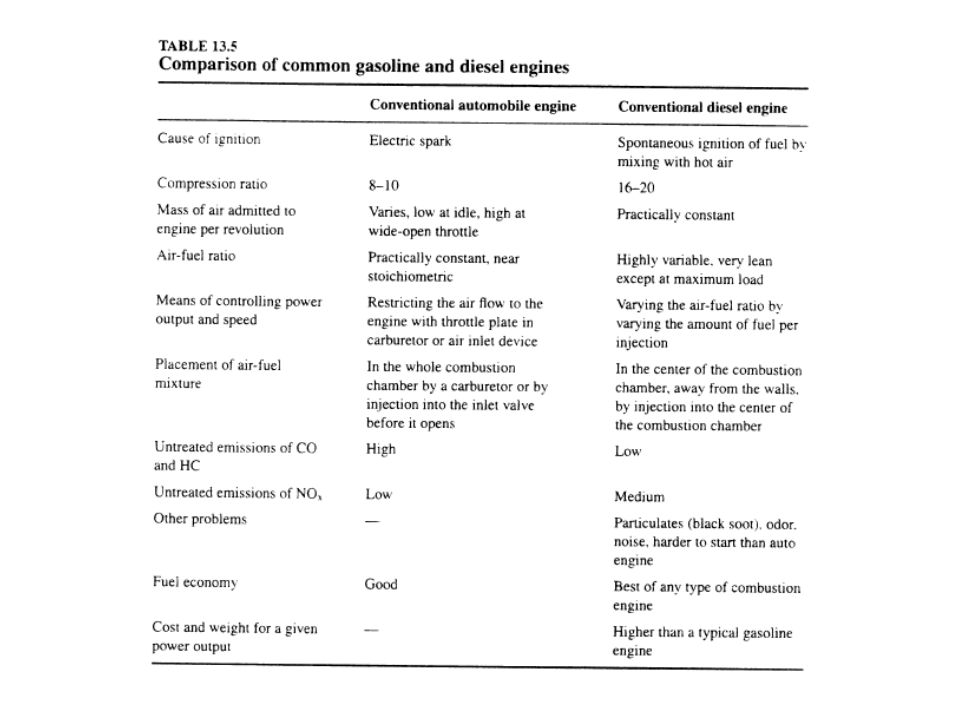
4.1 Diesel Engines Next slide (Table 13.5) The differences between conventional gasoline and diesel engines.
 The differences between conventional gasoline and diesel engines.")
112
When a gasoline engine is running at its maximum temperature, it will sometimes continue to run even after the ignition is turned off as a result of the spontaneous ignition by mixing with hot gas. Most auto engines have “anti-dieseling” devices in their fuel systems to prevent this.

113
In a conventional auto a small amount of air per revolution enters the engine at idle (closed throttle plate) and a much larger amount enters at wide-open throttle. The ratio for a typical engine between maximum and minimum air flow is about 80:1. Diesel engines have no throttle; they put practically the same amount of air per revolution into the engine at idle and at full power.

114
4.2 Gasoline-Powered Two-stroke Engines
These engines discharge exhaust gas and bring in inlet gas simultaneously. Their spark plugs fire every revolution. They do not have mechanical valves, but use ports, passages, and crankcase compression to move the inlet gas into the cylinder.

115
They are used in some lawnmowers, chain saws, many portable power tools, some motocycles, and most outboard boat motors. They are simpler, cheaper, smaller, and lighter for a given power output than typical automobile engines. But they are less fuel efficient and have much higher exhaust emissions.

116
4.3 Gas Turbine Engines These engines do their compression and expansion with rapidly rotating (e.g., 20,000 rpm) compressors and turbines instead of the piston and cylinder arrangement in most IC engines. Their burners operate in steady flow instead of intermittently, as in other IC engines, and they use large amounts of excess air.
 compressors and turbines instead of the piston and cylinder arrangement in most IC engines. Their burners operate in steady flow instead of intermittently, as in other IC engines, and they use large amounts of excess air.")
117
They are used in jet aircraft, helicopters, small electric power installations, and a few trucks.
Turbines have less weight for a given power output than a typical automobile engine.

118
They have satisfactory fuel economy at full load but very poor fuel economy at part load.
They respond slowly to changes in throttle setting. These drawbacks have defeated all efforts to build a cost-competitive automotive gas turbine engine.

119
4.4 Other Options (1) Electric Vehicles
The most common suggestion is the battery-powered auto. It produces negligible local air pollutant emissions. An electric auto is also quieter than the IC-powered auto.

120
The IC engine takes its oxidizer from the air, typically 15 pounds of air per pound of fuel.
The battery car carries both fuel and oxidizer with it. The extra weight is a major handicap for cars using traditional lead-acid batteries. Recharging is another problem.

121
(2) Fuel Cell Vehicles Fuel cells react fuel electrochemically with oxygen without burning it. They have a higher thermal efficiency than any fuel-burning engine. To date, they are only practical for hydrogen as a fuel, which is satisfactory for space travel, but not for autos.

122
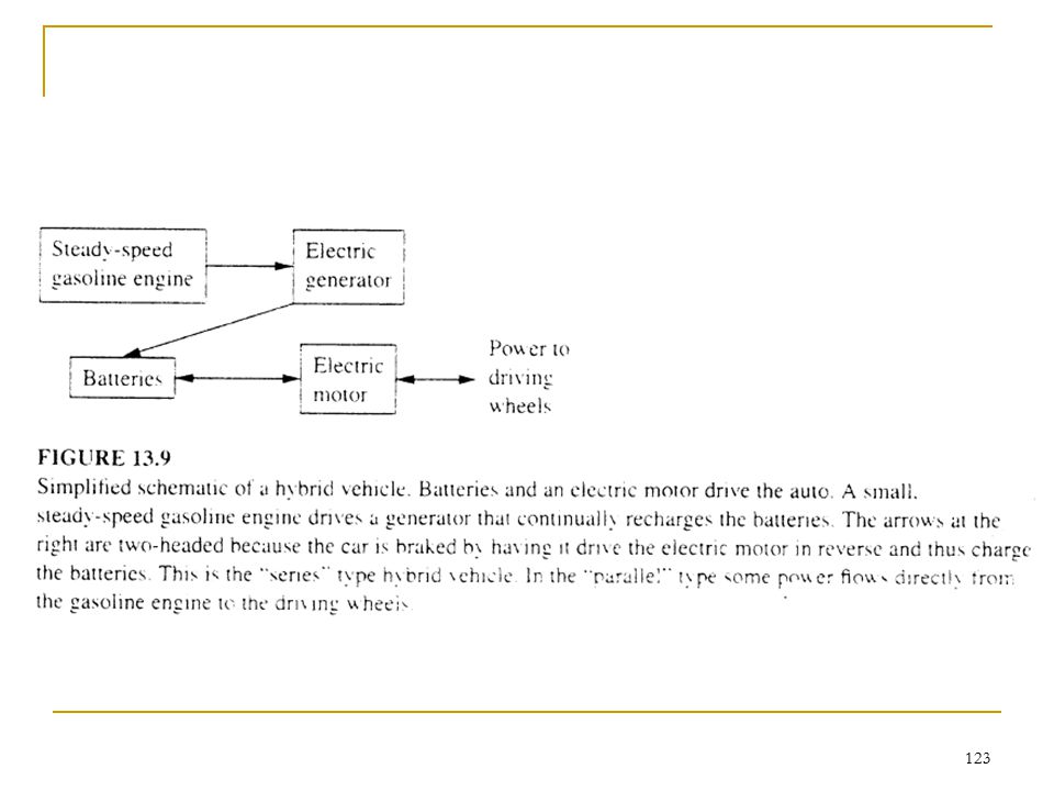
(3) Hybrid Vehicles One solution to the poor range of electric vehicles is to charge the batteries as you drive. This is done by hybrid vehicles, see Fig (next slide).
.")
124
In steady level highway driving only perhaps 10% of the engine’s maximum power is used.
A hybrid vehicle has a much smaller gasoline engine than the same-sized conventional auto, and it runs steadily whenever the auto is in use. That makes it much more efficient and makes its emissions much less than the larger, variable speed engine of a conventional auto.

125
The battery system absorbs power in normal driving and provides bursts of power for passing or hill climbing. The size of battery required is much less than for an all-electric vehicle. The manufacturers claim that the hybrid vehicles have about twice the fuel economy and one-tenth the pollutant emissions of conventional vehicles of comparable size and performance.

Similar presentations


 Patel Vidhi A.>")


