Download presentation
Presentation is loading. Please wait.

1
Current Electricity Chapter 20

2
Potential Energy High PE Low PE
If you do work against gravity, the gravitational field stores that energy as Gravitational Potential Energy, GPE If you do work against an electrostatic force, the electric field stores that energy as electric Potential Energy, EPE

3
Electric Potential Energy
Electrostatic Force is conservative Electrical potential energy is the energy contained in a configuration of charges. Like all potential energies, when it goes up the configuration is less stable; when it goes down, the configuration is more stable. The unit is the Joule.

4
Electric Potential Energy
Electrical potential energy increases when charges are brought into more unstable configurations. Lower PE Higher PE Fe + + + + d Stable Unstable Moving q1 closer to q2 requires work and that will increase the PE of the charge. Work against electric force increases electric PE

5
Electric Potential Energy
Electrical potential energy decreases when charges are brought into more stable configurations. Higher PE Lower PE Fe - - + + d Unstable Stable q1 will naturally move or fall towards q2 in the direction of E. No work is required and the PE of the charge will decrease. Work with the electric force decreases electric PE

6
Electric Potential Energy
Moving a charge in an electric field requires work. This work stores potential energy. Electric Potential UNITS: J/C or Volt Electric Potential, V, is electric potential energy per charge. At every location, a charge has a position-dependent potential. Potential difference is simply the difference in electric potential at any 2 points

7
Producing Electric Energy
Electric energy provides the means to transfer large quantities of energy over great distances with little loss.

8
Producing Electric Energy
Because electric energy can so easily be changed into other forms, it has become indispensable in our daily lives.

9
Circuit Charges flow from high to low V through conducting wire High V A This flow of positive charge is called conventional current Low V B The flow stops when the potential difference between A and B is zero.

10
Potential Difference and Current
High V To be a circuit, charges must flow continuously thru a loop, returning to their original position and cycling thru again. To do so requires energy input, a charge pump that raises the electric potential of the charge Lower V

11
Circuits require an electrical energy source – VOLTAGE SOURCE, DV
A circuit is simply a closed, conducting loop through which charges can continuously move Energy Pump +DV Flow of charge is CURRENT, I

12
Producing Electric Current (Charge Pump)
1. Voltaic or galvanic cell converts chemical E to electric E. A battery is made up of several galvanic cells connected together. 2. Photovoltaic cell, or solar cell— changes light energy into electric energy.

13
- + Requirements of a Circuit 1. Closed conducting loop
2. An energy source that maintains an electric potential difference, DV, across the ends of the circuit. Low V Low energy DV High V High energy Energy Source Pumps charge from – to + terminal maintains a DV across the circuit - +

14
Current Once the two requirements of a circuit are met, charge will flow. Rate of charge flow is called CURRENT Electric current is represented by I I = DQ/t Unit of current: Ampere (A) 1 A = 1 C/s
 1 A = 1 C/s.")
15
Current A 2 mm long cross section of wire is isolated and 20 C of charge is determined to pass through it in 40 s. I = _____________ A 20C/40s = 0.5

16
Conventional Current Direction
Current is in the direction of + charge flow. In reality, the particles that carry charge through a wire are mobile electrons which move in a direction opposite conventional current. DV - + I

17
Vdrift ≈ 10-6 m/s or 1 m/hr (SLOW!!!)
I = Q/t DV The charge carriers are densely packed into the wire, so there does not have to be a high speed to have a high current. That is, the charge carriers do not have to travel a long distance in a second, there just has to be a lot of them passing through the cross section.

18
Resistance An electron traveling through the wires and loads of a circuit encounters resistance, R. Resistance is a hindrance to the flow of charge. The amount of current in a circuit depends on BOTH the potential difference across the circuit, DV, AND the total resistance in the circuit, R. LOAD I I Energy Source DV

19
Water Flow through pipe Current through Circuit
Flow rate depends on - pump pressure - resistance of pipe which depends on pipe length and diameter Current depends on - Voltage difference, DV - Resistance of circuit elements

20
Resistance L A Resistivity (W m)
Materials and elements in a circuit offer resistance to the flow of charge. L A Resistivity (W m) Conductors: r ~10-8 Wm Insulators: r ~ Wm pHet Sim
 Conductors: r ~10-8 Wm. Insulators: r ~ Wm. pHet Sim.")
21
Resistance A. d 2L Rank the following circuit elements from highest resistance to lowest resistance. 2d 2L B. A > C > B > D d L C. 2d L D.

22
To produce electric current, I, a potential difference, DV, is required. Simon Ohm established experimentally that the current in a metal wire is proportional to the potential difference applied to its ends. Current flow does NOT depend only on voltage. Charge traveling through the wires and loads of a circuit encounters resistance, R. Resistance is a hindrance to the current. The higher the resistance, the smaller the current.

23
Ohm’s Law Every element in a circuit obeys Ohm’s Law Resistance
Units: Ohms (W) Current Units: Amperes (A) Electric potential Units: Volts (v) Every element in a circuit obeys Ohm’s Law
 Current. Units: Amperes (A) Electric potential. Units: Volts (v) Every element in a circuit obeys Ohm’s Law.")
25
Circuit Components + - + - Voltage Source Light bulb Battery Resistor
Wire Switch

26
In which circuit does the light bulb have highest resistance
In which circuit does the light bulb have highest resistance? What are the resistances of each bulb? A ΔVA = -6V ΔVB = -6V 6V 0V 1A + - 6 V 2A + - 6 V A. B. 6V 0V RA = ΔVA / I = 6/1 = 6 Ω RB = ΔVB / I = 6/2 = 3 Ω

27
Which of the following will cause the current through an electrical circuit to decrease? Choose all that apply. a. decrease the voltage b. decrease the resistance c. increase the voltage d. increase the resistance

28
Kirchoff’s Rules I = I1 + I2 (Conservation of charge) I I2
1. Junction Rule At any junction point in a circuit, the sum of all the currents entering the junction must equal the sum of all currents leaving the junction Current into junction = Current out of junction (Conservation of charge) I I2 I1 R1 R2 I = I1 + I2
 I. I2. I1. R1. R2. I = I1 + I2.")
29
10 A What is the current in the unknown wire and what are the directions of the currents? 4 A 6 A 5 A 2 A 4 A 14 A ? 11 A

30
Kirchoff’s Rules (Conservation of energy) + - DVbat
2. Loop Rule The sum of the potential differences across all elements around any closed loop of a circuit must be zero. (Conservation of energy) + - R1 R2 R3 DV is negative (voltage drop) across elements in the circuit. DV is positive (voltage gain) across the battery. DVbat
 + - R1. R2. R3. DV is negative (voltage drop) across elements in the circuit. DV is positive (voltage gain) across the battery. DVbat.")
31
What is the voltage drop across each of the bulbs
What is the voltage drop across each of the bulbs? The bulbs have the same resistance. Outer Loop -3 V -3 V -6 V Inner Loop + - +6 V

32
Two Types of Connections
When there are 2 or more electrical devices in a circuit with an energy source, there are a couple of ways to connect them.

33
Series Connection When devices are in series, all of the current going through one device goes through the other 1 2 I A B Device 1 and 2 are in series. To go from A to B, all the charge passing through 1 must go through 2. The SAME CURRENT goes through resistors in series. The total R is greater than each individual resistor

34
Parallel Connection When devices are in parallel, the current splits; some current goes through one device, some through the other. In going from A to B, a charge goes through one device only. KJR I = I1+I2 1 I I I1 A B I2 2 Device 1 and 2 are in parallel. More charge (current) goes through path of least resistance Resistors in parallel have the SAME VOLTAGE DROP. The total R is less than each individual resistor
 goes through path of least resistance. Resistors in parallel have the SAME VOLTAGE DROP. The total R is less than each individual resistor.")
35
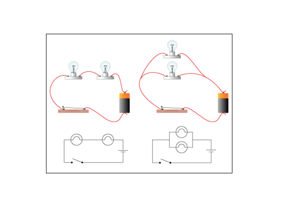
Circuit Connections

36
Series Circuit–How do the brightnesses compare?
Which circuit has the greater current flow? Does the charge get used up? the circuit with less load or less resistance In a closed loop, current flow is the same through every element (light bulbs 1, 2, and 3 are equally bright) less I (more resistance) More I (less resistance) dimmer brighter 1 2 3 + - + -
 less I (more resistance) More I (less resistance) dimmer. brighter")
37
Increases, There are more pathways so less resistance
Parallel Connections As the number of light bulbs (resistance) increases, what happens to the current through the circuit? Increases, There are more pathways so less resistance less I More I + - + - I 3I
 increases, what happens to the current through the circuit Increases, There are more pathways so less resistance. less I. More I I. 3I.")
38
Series Connections If one resistor is turned off (a light bulb goes out), what happens to the other resistors in the circuit? If one resistor goes out, there is no longer a closed loop for current flow and all other devices in series will go out. There is an OPEN CIRCUIT

39
Parallel Connections If on resistor is turned off (a light bulb goes out), what happens to the other resistors in the circuit? If one resistor goes out, there is still a closed loop for current flow and so the other devices in series will stay on

40
Energy Transfer and Power
When a LOAD is put on the circuit (light bulb, beeper, motor…), electrical energy is transformed to other, useful forms of energy. LOAD An electrical circuit is simply an energy transformation tool. Rate of energy transformation/transfer is POWER Energy Source
, electrical energy is transformed to other, useful forms of energy. LOAD. An electrical circuit is simply an energy transformation tool. Rate of energy transformation/transfer is POWER. Energy Source.")
41
Energy Transfer and Power
LOAD POWER, P, is the rate that energy is supplied to the load or the rate of work done on the charge. Energy Source Unit of Power: Watt (W) 1 W = 1 J/s
 1 W = 1 J/s.")
42
Energy transfer and Power
POWER, P, is the rate that energy is supplied to the load or the rate of work done on the charge. LOAD 60 Watt light bulb means 60 J of energy delivered to bulb every second OR 60 J of energy used by the bulb per second Energy Source

43
Electric heater. An electric heater draws 15. 0 A on a 120 V line
Electric heater. An electric heater draws 15.0 A on a 120 V line. How much power does it use and how much does it cost per month (30 days) if it operates 3.0 h per day and the electric company charges 10.5 cents per kW-h? To operate it for 30 days, 3 hr/day would total 90hrs and would use
 if it operates 3.0 h per day and the electric company charges 10.5 cents per kW-h To operate it for 30 days, 3 hr/day would total 90hrs and would use.")
44
Will a fuse blow? Determine the total current drawn by all the devices used at once. Will they blow a 20-A fuse? YES

45
Equivalent Resistance – Resistors in Series
+ - R3 -DV1 -DV2 -DV3 DVbat (Kirchoff’s Loop Rule) Each element obeys Ohms Law I REq + - DVbat
 Each element obeys. Ohms Law. I. REq. + - DVbat.")
46
Equivalent Resistance – Resistors in Series
This circuit can be replaced by R1 I R3 + - this one where V + - Req I V

47
+ - +DV Equivalent Resistance – Resistors in Parallel I1 I I2 I3
Kirchoff’s Junction Rule: R1 I1 I I2 R2 + - R3 I3 +DV

48
Equivalent Resistance – Resistors in Parallel
This circuit can be replaced by this one where + - Req I V

49
Series or Parallel? The light bulbs are identical and have identical resistance, R. Which configuration produces more light? Which way do you think the headlights of a car are wired? More pathways, Less resistance, More current More light

50
DO NOW What is the equivalent resistance of the circuit
DO NOW What is the equivalent resistance of the circuit? What is the current through the circuit? Req = 18W 6 W 8 W + - 4 W I I + - 12 V 12 V Ohms Law

51
+ - The 8 W one Rank, from highest to lowest, the voltage between
A and B, C and D, D and E E and F -2.68V -4.02V -5.36V 4W 6W 1 (highest) 8W F D E C + - I 4 3 2 If the resistors were light bulbs, which would be brightest? B A 12 V The 8 W one
 8W. F. D. E. C. + - I If the resistors were light bulbs, which would be brightest B. A. 12 V. The 8 W one.")
52
+ - + - Example - What is the equivalent resistance of the circuit?
Req = 1.8W 6 W 8 W + - + - 12 V 12 V The equivalent resistance of resistors in parallel is less than the smallest single resistance

53
+ - A=B > F=E > D=C The 4 W one
Rank the currents at points A-F from greatest to least A=B > F=E > D=C 4 W F E If the resistors were light bulbs, which would be brighter? 8 W D C The 4 W one + - B A 12 V

54
Series and Parallel Resistors – Two 100 W resistors are connected a) in series and b) in parallel to a 24.0 V battery. What is the current through each resistor? What is Req of each circuit? Req = 150 W 100 W 50 W + - + - I = 0.20 A I I This is the current through each resistor 30 V 30 V 50 W Req = 33W I3 I2 I1 = 0.91 A 100 W I2 = 0.30A I1 I1 + - + - I1 I3 = 0.61 A 30 V 30 V

55
Series and Parallel Resistors – Two 100 W resistors are connected a) in series and b) in parallel to a 24.0 V battery. What is the current through each resistor? What is Req of each circuit? Req = 33W 50 W I3 I2 + - 100 W 30 V I + - 30 V

56
Kirchoff’s Junction Rule
Find the current through each resistor and the current drawn from the battery. 1. Draw and label the current flow in the circuit 12W 2. Apply Kirchoff’s Rules I3 Loop1 Kirchoff’s Loop Rule I2 2W 4W I Loop2 12 V Kirchoff’s Junction Rule

57
Circuit Components V Voltmeter A Ammeter W Ohmmeter

58
Measuring Current Ammeter – measures current
Current to be measured must pass through the ammeter, so it must be placed in SERIES mode in the circuit. Ideally ammeters have ZERO resistance so that they do not affect the energy of the circuit

59
Measuring Voltage Voltmeter – measures voltage Does NOT require the current to pass through it. It must be placed in parallel to the circuit element. Ideally voltmeters have INFINITE resistance so that they do not draw current away from circuit.

61
For the circuit below, all resistors have the same value, R (10 W)
Draw and label the current flow Calculate the equivalent resistance of the circuit Calculate the total current provided by the battery. Calculate the current in resistor 3 Calculate the current in resistor 5 R1 R3 82V R5 I I3 I2 I4 I5 R2 R4 R6 R8 R7

62
R1 R3 R5 R56 R6 R8 R7 R34567 R456 I5 I3 I I3 I I5 I2 I4 I4 I2 I3 I I

63
I R1 R234567 R8 R2 I I3 I2 R1 R34567 R8 I Req 82V

64
For the circuit below, all resistors have the same value, R (10 W)
Draw and label the current flow Calculate the equivalent resistance of the circuit Calculate the total current provided by the battery. Calculate the current in resistor 3 Calculate the current in resistor 5 Req = 2 8/11 R = 27.3W I = 3A I3 = 33/40 A = 0.825A I5 = 0.275A R1 R3 82V R5 I I3 I2 I4 I5 R2 R4 R6 R8 R7

65
Example– Calculate the missing information in the table for the following series-parallel network. Find the equivalent resistance of the circuit. R1 R2 R3 DV (v) I (A) R (W) Bat 2.0 R1 5.0 R2 3.5 R3 1.5 R4 4.0 R5 1.0 R6 I1 I2=1.5 14 I I=2 I3 = 1.0 DVbat R4 I4 R5 I R6 Req = 7 W
 I. (A) R (W) Bat R R R R R R6. I1. I2= I. I=2. I3 = 1.0. DVbat. R4. I4. R5. I. R6. Req = 7 W.")
Similar presentations


 Q: charge in Coulombs (C) t: time in seconds.>")


>")


 to a location.>")
