Download presentation
Presentation is loading. Please wait.

1
5/10KW TQG DC CIRCUITS Preheat Circuit Crank Circuit Fuel Circuit
Field Flash Circuit Battery Charging Circuit

2
PREHEAT CIRCUIT In a cold weather environment with S1 in position #1, the intake manifold/ head fails to warm up

3
CIRCUIT COMPONENTS K18: Preheat relay HTR1, and HTR2: heaters
add HTR3 & 4 for 10KW units

4
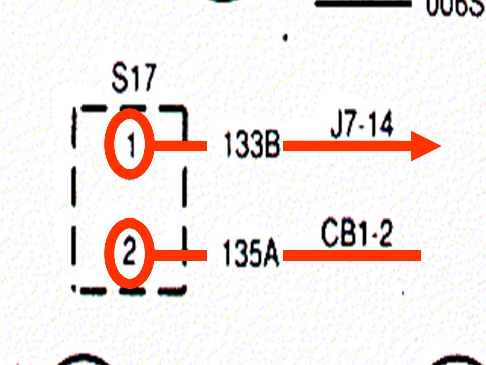
CB1-Pushed in S17 Pulled out Normal Start Here

5
Start Here L4 1 L4 + B1 +

9
THIS IS THE BEGINNING OF THE RETURN PATH
Once current LEAVES the S1 it will take the same path back to the power source.

18
Don’t go thru the K2 because it is not energized.

19
K18 IS’NT ENERGIZED YET CONTACTS STILL OPEN

20
Now the K18 is energized. L4 1

21
Contacts close

24
S-1 is in position 5, generator fails to crank.
CRANK CIRCUIT S-1 is in position 5, generator fails to crank.

25
CIRCUIT COMPONENTS K16: Crank disconnect relay K2: Cranking relay.
L4: Starter solenoid. B1: Cranking motor(starter).
.")
26
Start Here

27
Energize K16 Start Here

34
TB5 12

36
TB6

46
Don’t go thru the K2 because it is not energized.

48
Now K16 is energized.

49
Energize K2 Start Here

58
S1 Once the current reaches the S1 it takes the same path back to the power source.

59
Start Here

61
L4 is energized and the starter motor engages.

62
FUEL CIRCUIT With the S-1 in position 5, the generator cranks and fails to start/ runs & when the S-1 is released TO position 4, the generator shuts OFF.

63
CIRCUIT COMPONENTS L5: Fuel shut off solenoid. E2: Fuel pump.

64
S14 WILL 900RPM Start Here

65
Energize E2 Start Here

74
Once current reaches the S1 it will take the same path back to the power source.

83
Don’t go thru the K2 even though its energized.

84
You cant go thru the K18 since its not energized.

85
Now E2 is energized.

92
Once current reaches K2 A1
It follows current back to the power source.

94
Once current reaches TB4-12, it flows back to power source.

95
INITIAL FIELD FLASH CIRCUIT
While holding S1 is in position 5, generator cranks and runs. You observe no hertz and no volts on the meters M1 & M2

96
CIRCUIT COMPONENTS K15: Field flash relay. G1: Main AC generator

97
S14 Senses the Engine Speed Via MPU
@ 900RPM S14 OPENS & K16 de-energizes F1 F2 G1 Start Here

98
Energize K15 Start Here

104
Once current reaches the S1 it will take the same path back to the power source.

115
Now K15 is energized.

116
Flash G1 Start Here

130
Once current reaches TB5-14, it flows back to power source.

131
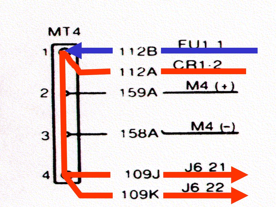
BATTERY CHARGING CIRCUIT
With S1 in position 4, and the generator running. The battery charging ammeter (M4) shows a discharge reading.
 shows a discharge reading.")
132
CIRCUIT COMPONENTS G2: Battery charging alternator. FU1: Fuse

133
Start Here

134
Start Here

138
Once current reaches the S1 it will take the same path back to the power source.

150
Start Here

Similar presentations


 + - SW #1 1,2 Both 300A SW #2 1,2 Both 200A AC Gen. Main Eng.>")


