Download presentation
Presentation is loading. Please wait.

1
Chapter 4: Sheet Metal Forming Shafizan Bt. Shariffuddin School of Manufacturing Engineering UniMAP 4.3 USING PATTERNS AND CUTTING METALS

2
Using Patterns and Making Drawings Sheet metal articles are made of flat pieces of metal cut according to outlines that are drawn or traced on the sheets of metal. To obtain the current size and shapes, patterns are used. These patterns may be drawn on paper first, then transferred to the metal, or they may be laid out directly on the metal.

3
Definition a)Templates or master pattern- patterns that are used repeatedly and are made of metal. b)Stretchout – the distance across the flat pattern or flat piece of metal before it is formed into shape. The illustration in Figure 1 shows the stretchouts for square and cylindrical jobs.
Stretchout – the distance across the flat pattern or flat piece of metal before it is formed into shape. The illustration in Figure 1 shows the stretchouts for square and cylindrical jobs..")
4
Figure 1. Stretchouts for square and cylindrical objects.

5
c)Layout – refers to the methods of developing the lines which form the patterns. The common layout methods are :- i.Parallel line development ii.Radial line development iii.Triangulation

6
i) Parallel line development Parallel line development is based upon the fact that a line that is parallel to another line is an equal distance from that line at all points. Objects that have opposite lines parallel to each other or that have the same cross-sectional shape throughout their length are developed by this method. To gain a clear understanding of the parallel line method, we will develop, step by step, a layout of a truncated cylinder (fig. 2(a)).
)..")
7
Figure 2(a): Truncated cylinder Figure 2(b): Development of a truncated cylinder
: Truncated cylinder Figure 2(b): Development of a truncated cylinder")
8
This piece of sheet metal is developed in the following procedure: 1.First, draw a front and bottom view by orthographic projection (fig.2(b), view A). 2.Divide half the circumference of the circle (view A) into a number of equal parts. The parts should be small enough so that when straight lines are drawn on the development or layout between division points, they will approximate the length of the arc. Project lines from these points to the front view, as shown in view B. These resulting parallel lines of the front view are called ELEMENTS. 3.Lay off the baseline, called the STRETCH-OUT LINE, of the development to the right of the front view, as shown in view C.
 into a number of equal parts. The parts should be small enough so that when straight lines are drawn on the development or layout between division points, they will approximate the length of the arc. Project lines from these points to the front view, as shown in view B. These resulting parallel lines of the front view are called ELEMENTS. 3.Lay off the baseline, called the STRETCH-OUT LINE, of the development to the right of the front view, as shown in view C..")
9
4. Divide the stretch-outline into twice the number of equal parts equal to each division of the circumference on the half circle of the orthographic view (view C). 5. Erect perpendicular lines at each point, as shown in view C. 6. Using a T-square edge, project the lengths of the elements on the front view to the development (View D). 7. Using a curve (french or other type), join the resulting points of intersection in a smooth curve. When the development is finished, add necessary allowances for warns and joints, then cut out your patterns.
. 5. Erect perpendicular lines at each point, as shown in view C. 6. Using a T-square edge, project the lengths of the elements on the front view to the development (View D). 7. Using a curve (french or other type), join the resulting points of intersection in a smooth curve. When the development is finished, add necessary allowances for warns and joints, then cut out your patterns..")
10
ii) Radial line development The radial line method of pattern development is used to develop patterns of objects that have a tapering form with lines converging at a common center.
 Radial line development The radial line method of pattern development is used to develop patterns of objects that have a tapering form with lines converging at a common center.")
11
Figure 3: Example of radial line development

12
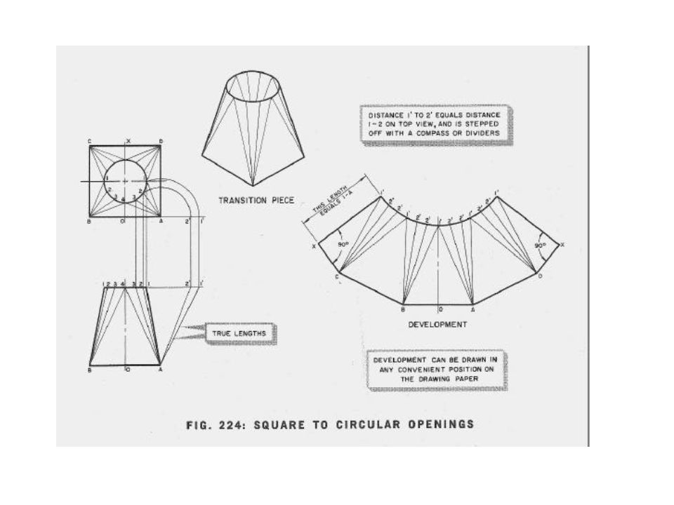
iii) Triangulation Triangulation is slower and more difficult than parallel line or radial line development, but it is more practical for many types of figures. Additionally, it is the only method by which the developments of warped surfaces may be estimated. In development by triangulation, the piece is divided into a series of triangles as in Radial line development.

13
Figure 4: Triangulation of a warped transition piece join ing a large, square duct and a small, round duct

15
d)Pictorial drawings – show the object as it actually appears after formed into shaped. This is illustrated in Figure 5. Such a drawing cannot serve as means of giving accurate information for the fabrication of the project because the true shape and size of the object is not shown. Figure 5: Pictorial drawings show the type of objects as they appear after forming.

16
e) Mechanical drawing – show the exact size and shape of each size. See Figure 6. It is only necessary to make the number of view required to show the size and shape of the object.

17
Figure 6.The white areas in the drawing at the right are mechanical or working drawings. The drawings at the left and top show the placement of various views in relation to each other.

18
Pattern Information The master pattern should contain all of the allowances and details necessary to fabricate the job. These includes :- a) Allowances for edges –Different types of edges are used to stiffen the edges of the sheet metal articles, and to eliminate the sharp edges. The amount of metal allowed for the edge depends upon the type of edge used.
 Allowances for edges –Different types of edges are used to stiffen the edges of the sheet metal articles, and to eliminate the sharp edges. The amount of metal allowed for the edge depends upon the type of edge used..")
19
b) Allowances for seaming –Sheet metal parts are joined by seams of various kinds. The addition of the seams makes it necessary to add material to the pattern. *Allowance? In engineering and machining, an allowance is a planned deviation between an actual dimension and a nominal or theoretical dimension. For example, an area of excess metal may be left because it is needed to complete subsequent machining.

20
c) Prick punching brake lines –The place or line where the metal to be bend or folded is called brake line. On metal patterns, the brake line are prick punched and shown by ‘x’. See figure 7. Figure 7

21
d) Notching and clipping –Notching and clipping are used to cut away portions of the metal to prevent over – lapping and budging on seams and edges. The operations are different as illustrated by Figure 8. Figure 8:Notching and clipping

22
Cutting Metals Cutting straight and curved lines The sheet metal worker generally uses four different snips for all his cutting. 1)The bulldog snips are used for general cutting in heavy metal – 24 gage or thicker. 2)The combination snips are also for general cutting from 24 gage and thinner. 3)Right-hand airplane snip.
The bulldog snips are used for general cutting in heavy metal – 24 gage or thicker. 2)The combination snips are also for general cutting from 24 gage and thinner. 3)Right-hand airplane snip..")
23
4) Left-hand airplane snip –Both right-hand and left-hand airplane snips are used for both heavy and light steel metal. They can cut to 16 gage, cut very small land complex curves, also to cut inside circles and inside square, as shown in Figure 9.

24
Figure 9. Airplane snips are used to make small or complex cuts.

25
Figure 10 : proper and improper ways of cutting X X √ √ √

26
Care and use of snips 1.Keep the small piece of metal over the bottom blade of the snips. 2.Trim off excess metal before making the cut on the line. 3.Whenever possible, rest the blade and handle of the snips on the workbench. 4.When notching keep the end of the snips blade at the point where the notch will end. 5.Keep oil from the blades snips. 6.Cut only sheet metal with snips.

27
Bench Lever Shear A shear which is used in almost every sheet metal shop is shown in Figure 11. This is a heavy duty shears able to cut to 10 mm thick metal with ease. They have a compound leverage system for greater power. When using this type of sheets, keep the good piece of metal over the lower blade and run the scrap piece under blade since the piece that goes under the upper blade will be curled and disturbed by the cutting action.

28
The blades are designed to cut curves, and circles as well as straight lines. It posses a fixed lower blade and a moving upper blade. The sheet being cut is prevented from tilting by a clamping device which can be adjusted to the thickness of the sheet. The knife-edge cutter of the upper blade is curved so that the opening angle at the point of cut remains constant.

29
Figure 11: Bench Lever Shear

30
Guillotine Shear The guillotine shear below may be set for cutting steel or non-ferrous metal sheet, as well as plastics, wire netting etc. The extremely logical construction of the shear, produces several special new features, of which the following deserving of mention :- –Rear stop bar can be operated from the front with fast movement and visual display scale. –No lubrication point –Quick blade gap adjustment –Unobstructed view from above of the material being cut – no parallex errors. –Variable cutting table adjustment –Low noise etc.

31
Guillotine Shear With Pivoting Top Beam 1.Back stop adjusting and clamping lever 2.Reading Optics 3.Treadle Switch 4.Main Switch 5.Cutting Gap Adjusting Device 6.Hang-up Peg Figure 12

32
Figure 13

Similar presentations