Download presentation
Presentation is loading. Please wait.

1
Practical Database Design Methodology and Use of UML Diagrams
Chapter 10 Practical Database Design Methodology and Use of UML Diagrams

2
Chapter 10 Outline The Role of Information Systems in Organizations
The Database Design and Implementation Process Use of UML Diagrams as an Aid to Database Design Specification Rational Rose: A UML-Based Design Tool Automated Database Design Tools

3
Practical Database Design Methodology and Use of UML Diagrams
Target database managed by some type of database management system Various design methodologies Large database Several dozen gigabytes of data and a schema with more than 30 or 40 distinct entity types

4
The Role of Information Systems in Organizations
Organizational context for using database systems Organizations have created the position of database administrator (DBA) and database administration departments Information technology (IT) and information resource management (IRM) departments Key to successful business management
 and database administration departments. Information technology (IT) and information resource management (IRM) departments. Key to successful business management.")
5
The Role of Information Systems in Organizations
Database systems are integral components in computer-based information systems Personal computers and database system-like software products Utilized by users who previously belonged to the category of casual and occasional database users Personal databases gaining popularity Databases are distributed over multiple computer systems Better local control and faster local processing

6
Organizational Context for using Database Systems
Consolidation of data across organization Maintenance of complex data Simplicity of developing new applications Data independence Protecting application programs from changes in the underlying logical organization and in the physical access paths and storage structures External Schemas Allow the same data to be used for multiple apps with each application having its own view of the data

7
The Role of Information Systems in Organizations
Data dictionary systems or information repositories Mini DBMSs Manage meta-data High-performance transaction processing systems require around-the-clock nonstop operation Performance is critical

8
The Information System Life Cycle
Information system (IS) Resources involved in collection, management, use, and dissemination of information resources of organization
 Resources involved in collection, management, use, and dissemination of information resources of organization.")
9
The Information System Life Cycle
Macro life cycle Feasibility analysis Requirements collection and analysis Design Implementation Validation and acceptance testing

10
Phases of Information System Life Cycle
Feasibility Analysis Analyzing potential application areas Identifying the economics of information gathering and dissemination Performing cost benefit studies Setting up priorities among applications Requirement Collection and Analysis Detailed Requirements Collection Interaction with Users Design Design of Database System Design of programs that use and process the database

11
Phases of Information System Life Cycle
Implementation Information system is implemented Database is loaded & its transactions are implemented and tested Validation and Acceptance Testing Testing against user’s requirements Testing against performance criteria Deployment, Operation and Maintenance Data conversion Training System maintenance Performance monitoring Database tuning

12
The Information System Life Cycle
The database application system life cycle: micro life cycle System definition Database design Database implementation Loading or data conversion

13
The Information System Life Cycle
Application conversion Testing and validation Operation Monitoring and maintenance

14
Database System Life Cycle
System definition Defining scope of database system, its users and applications Database Design Logical and physical design of the database system on the chosen DBMS Database implementation Specifying conceptual, external and internal database definitions Creating empty database files Implementing software applications

15
Database System Life Cycle
Loading or data conversion Populating the database Application conversion Converting applications to the new system Testing and validation Operation Running the new system Monitoring and maintenance System maintenance Performance monitoring

16
The Database Design and Implementation Process
Design logical and physical structure of one or more databases Accommodate the information needs of the users in an organization for a defined set of applications Goals of database design Very hard to accomplish and measure Often begins with informal and incomplete requirements

17
The Database Design and Implementation Process
Main phases of the overall database design and implementation process: 1. Requirements collection and analysis 2. Conceptual database design 3. Choice of a DBMS 4. Data model mapping (also called logical database design) 5. Physical database design 6. Database system implementation and tuning
 5. Physical database design. 6. Database system implementation and tuning.")
19
The Database Design and Implementation Process
Parallel activities Data content, structure, and constraints of the database Design of database applications Data-driven versus process-driven design Feedback loops among phases and within phases are common

20
The Database Design and Implementation Process
Heart of the database design process Conceptual database design (Phase 2) Data model mapping (Phase 4) Physical database design (Phase 5) Database system implementation and tuning (Phase 6)
 Data model mapping (Phase 4) Physical database design (Phase 5) Database system implementation and tuning (Phase 6)")
21
Phase 1: Requirements Collection and Analysis
Activities Identify application areas and user groups Study and analyze documentation Study current operating environment Collect written responses from users

22
Phase 1 Requirements specification techniques Oriented analysis (OOA)
Data flow diagrams (DFDs Refinement of application goals Computer-aided

23
Phase 2: Conceptual Database Design
Phase 2a: Conceptual Schema Design Important to use a conceptual high-level data model Approaches to conceptual schema design Centralized (or one shot) schema design approach View integration approach
 schema design approach. View integration approach.")
24
Phase 2: Strategies for schema design Schema (view) integration
Top-down strategy Bottom-up strategy Inside-out strategy Mixed strategy Schema (view) integration Identify correspondences/conflicts among schemas: Naming conflicts, type conflicts, domain (value set) conflicts, conflicts among constraints Modify views to conform to one another Merge of views and restructure
 integration. Identify correspondences/conflicts among schemas: Naming conflicts, type conflicts, domain (value set) conflicts, conflicts among constraints. Modify views to conform to one another. Merge of views and restructure.")
25
Strategies for Schema Design
Top Down Strategy Start with a schema containing high-level abstractions and then apply successive top- down refinements

26
Strategies for Schema Design
Bottom-Up Strategy Start with a schema containing basics abstractions and then combine or add to these abstractions

27
Strategies for Schema Design
Inside-out Strategy Start with central set of concepts and then spread outward by considering new concepts in the vicinity of existing ones Mixed Strategy Use a combination of top-down and bottom-up strategies

28
Phase 2: Phase 2b: Transaction Design
Strategies for the view integration process Binary ladder integration N-ary integration Binary balanced strategy Mixed strategy Phase 2b: Transaction Design In parallel with Phase 2a Specify transactions at a conceptual level Identify input/output and functional behavior Notation for specifying processes

29
View Integration Strategies
Binary Ladder Integration Two similar schemas are integrated first and the resulting schema is then integrated with another schema The process is repeated until all schemas are integrated N-ary Integration All views are integrated in one procedure after analysis and specification of their correspondences Requires computerized tools for large designs

30
View Integration Strategies
Binary Balanced Strategy Pairs of schemas are integrated first and the resulting schemas are then paired for further integration. This process is repeated until a final global schema Mixed Strategy Schemas partitioned into groups based on their similarity; each group integrated separately.

31
Conceptual Schema Design
Goal Complete understanding of the database structure, semantics, interrelationships and constraints Serves as a stable description of the database contents Good understanding crucial for the users and designers Diagrammatic description serves as an excellent communication tool

32
Desired Characteristics of Conceptual Data Model
Expressiveness Able to distinguish different types of data, relationships and constraints Simplicity and Understandability Easy to understand Minimality Small number of distinct basic concepts Diagrammatic Representation Diagrammatic notation to represent conceptual schema Formality Formal unambiguous specification of data

33
Approaches to Conceptual Schema Design
Centralized Schema Design Approach Also known as one-shot approach Requirements of different applications and user groups are merged into a single set of requirements and a single schema is designed Time consuming, places the burden on DBA to reconcile conflicts View Integration Approach Schema is designed for each user group or application These schemas are then merged into a global conceptual schema during the view integration phase More practical

34
Schema Integration Identifying correspondence and conflict among different schemas Naming conflicts Synonyms: The same concept but different names e.g. entity types CUSTOMER and CLIENT Homonyms: Different concepts but same name e.g. entity type PART as computer parts and furniture parts Type Conflicts: Representing the same concept by different modeling constructs e.g. DEPARTMENT may be an entity type and an attribute Domain Conflicts: Attribute has different domains Also known as value set conflicts e.g. SSN as an integer and as a character string Conflict among constraints: Two schemas impose different constraints e.g. different key of an entity type in different schemas

35
Schema Integration Modifying views to conform to one another
Modifying schemas to conform to one another Merging of views Merging Schemas to create a global schema Specifying mappings between views and global schema Time consuming and difficult Restructuring Simplifying and restructuring to remove any redundancies

36
View Integration Strategies

37
Phase 3: Choice of a DBMS Costs to consider
Software acquisition cost Maintenance cost Hardware acquisition cost Database creation and conversion cost Personnel cost Training cost Operating cost Consider DBMS portability among different types of hardware

38
Transaction Design Design characteristics of known database transactions in a DBMS Types of Transactions Retrieval Transactions Used to retrieve data Update Transactions Update data Mixed Transactions Combination of update and retrieval Techniques for Specifying Transactions Input/output Functional Behavior

39
Choice of DBMS Many factors to consider Technical Factors
Type of DBMS: Relational, object-relational, object etc. Storage Structures Architectural options Economic Factors Acquisition, maintenance, training and operating costs Database creation and conversion cost Organizational Factors Organizational philosophy Relational or Object Oriented Vendor Preference Familiarity of staff with the system Availability of vendor services

40
Phase 4: Data Model Mapping (Logical Database Design)
Create a conceptual schema and external schemas In data model of selected DBMS Stages System-independent mapping Tailoring schemas to a specific DBMS

41
Logical Database Design
Transform the Schema from high-level data model into the data model of the selected DBMS. Design of external schemas for specific applications Two stages System-independent mapping DBMS independent mapping Tailoring the schemas to a specific DBMS Adjusting the schemas obtained in step 1 to conform to the specific implementation features of the data model used in the selected DBMS Result DDL statements in the language of the chosen DBMS

42
Phase 5: Physical Database Design
Choose specific file storage structures and access paths for the database files Achieve good performance Criteria used to guide choice of physical database design options: Response time Space utilization Transaction throughput

43
Physical Database Design
Design the specifications for the stored database in terms of physical storage structures, record placements and indexes. Design Criteria Response Time Elapsed Time between submitting a database transaction for execution and receiving a response Space Utilization Storage space used by database files and their access path structures Transaction throughput Average number of transactions/minute Must be measured under peak conditions Result Initial determination of storage structures and access paths for database files

44
Phase 6: Database System Implementation and Tuning
Typically responsibility of the DBA Compose DDL Load database Convert data from earlier systems Database programs implemented by application programmers Most systems include monitoring utility to collect performance statistics

45
Database System Implementation and Tuning
During this phase database and application programs are implemented, tested and deployed Database Tuning System and Performance Monitoring Data indexing Reorganization Tuning is a continuous process

46
Database Design Tools Common Features Problems
Allow the designer to draw conceptual schema diagram in some tool-specific notation Allow model mapping Allow some level of design normalization Problems Most tools do nothing more than representing relationships among tables Most tools lack built-in methodology support Most tools have poor design verification system

47
Characteristics of a Good Design Tool
Easy-to-use interface Easy to use Customizable Analytical components For difficult tasks such as evaluating physical design alternatives or detecting conflicting constraints among views Heuristic components Automating design process using heuristic rules

48
Characteristics of a Good Design Tool
Trade-off analysis Comparative analysis in case of multiple alternatives At least at the conceptual design level Display of design results Displaying results in simple and easy to understand form Design Verification Verifying that the resulting design satisfies the initial requirements

49
Use of UML Diagrams as an Aid to Database Design Specification
Use UML as a design specification standard Unified Modeling Language (UML) approach Combines commonly accepted concepts from many object-oriented (O-O) methods and methodologies Includes use case diagrams, sequence diagrams, and statechart diagrams
 approach. Combines commonly accepted concepts from many object-oriented (O-O) methods and methodologies. Includes use case diagrams, sequence diagrams, and statechart diagrams.")
50
UML for Database Application Design
Advantages of UML Resulting models can be used to design relational, object-oriented, or object-relational databases Brings traditional database modelers, analysts, and designers together with software application developers

51
Different Types of Diagrams in UML
Structural diagrams Class diagrams and package diagrams Object diagrams Component diagrams Deployment diagrams

52
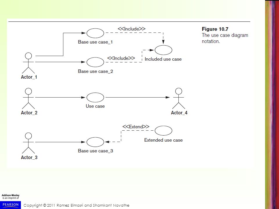
Different Types of Diagrams in UML
Behavioral diagrams Use case diagrams Sequence diagrams Collaboration diagrams Statechart diagrams Activity diagrams

54
Different Types of Diagrams in UML

55
Different Types of Diagrams in UML

56
Modeling and Design Example: UNIVERSITY Database

59
Rational Rose: A UML-Based Design Tool
Rational Rose for database design Modeling tool used in the industry to develop information systems Rational Rose data modeler Visual modeling tool for designing databases Provides capability to: Forward engineer a database Reverse engineer an existing implemented database into conceptual design

60
Data Modeling Using Rational Rose Data Modeler
Reverse engineering Allows the user to create a conceptual data model based on an existing database schema specified in a DDL file Forward engineering and DDL generation Create a data model directly from scratch in Rose Generate DDL for a specific DBMS

61
Data Modeling Using Rational Rose Data Modeler
Conceptual design in UML notation Build ER diagrams using class diagrams in Rational Rose Identifying relationships Object in a child class cannot exist without a corresponding parent object Non-identifying relationships Specify a regular association (relationship) between two independent classes
 between two independent classes.")
62
Data Modeling Using Rational Rose Data Modeler
Converting logical data model to object model and vice versa Logical data model can be converted to an object model Allows a deep understanding of relationships between conceptual and implementation models

63
Data Modeling Using Rational Rose Data Modeler
Synchronization between the conceptual design and the actual database Extensive domain support Create a standard set of user-defined data types Easy communication among design teams Application developer can access both the object and data models

64
Automated Database Design Tools
Many CASE (computer-aided software engineering) tools for database design Combination of the following facilities Diagramming Model mapping Design normalization
 tools for database design. Combination of the following facilities. Diagramming. Model mapping. Design normalization.")
65
Automated Database Design Tools
Characteristics that a good design tool should possess: Easy-to-use interface Analytical components Heuristic components Trade-off analysis Display of design results Design verification

66
Automated Database Design Tools
Variety of products available Some use expert system technology

67
Summary Six phases of the design process UML diagrams
Commonly include conceptual design, logical design (data model mapping), physical design UML diagrams Aid specification of database models and design Rational Rose and the Rose Data Modeler Provide support for the conceptual design and logical design phases of database design
, physical design. UML diagrams. Aid specification of database models and design. Rational Rose and the Rose Data Modeler. Provide support for the conceptual design and logical design phases of database design.")
Similar presentations


 Model.>")


