Download presentation
Presentation is loading. Please wait.

1
Dr. Mark Price – Spring 2011

2
An understanding of the way in which space missions are configured both from the point-of- view of the constituent subsystems, mission profile (i.e., the project aims) including the influence of the space environment. Appreciate the constraints and trade-offs which led to one mission configuration over another. Appreciate space activities from a commercial viewpoint and be familiar with basic management tools for planning work (e.g., Gant charts, Pert charts etc.) Make (valid) approximations and solve problems using a mathematical approach.
 Make (valid) approximations and solve problems using a mathematical approach..")
3
Basic elements of a space mission

4
Definition of different phases of a mission ◦ Concept ◦ Design ◦ Integration ◦ Testing ◦ Launch ◦ Operations ◦ End-of-life The different space environments ◦ NEO ◦ Deep space ◦ Other bodies The differing conditions (gravity, radiation, micrometeoroid, debris etc.) within each space environment How all this influences a spacecraft’s design
 within each space environment How all this influences a spacecraft’s design")
5
Crude overview: [Read: chapter 2, F&S] 1. Ground phase (vehicle construction) 2. Pre-launch phase (payload and rocket integration) 3. Launch phase 4. Space operations phase 5. Other (planetary, asteroid belt, cometary environments, de-orbital/end of life phase)
![Crude overview: [Read: chapter 2, F&S] 1. Ground phase (vehicle construction) 2.](http://images.slideplayer.com/15/4850079/slides/slide_5.jpg "Pre-launch phase (payload and rocket integration) 3. Launch phase 4. Space operations phase 5. Other (planetary, asteroid belt, cometary environments, de-orbital/end of life phase).")
6
Can be sub-divided further into: Manufacture stage Assembly stage Test and checkout stage Handling stage Transportation stage Storage (prior to rocket/payload integration)
")
7
Summary – you should now have an understanding of the various environments that a spacecraft could encounter: ◦ Gravity ◦ Vacuum ◦ Thermal ◦ Radiation ◦ Debris Also an understanding of how these environments affect the Spacecraft and its subsystems ◦ General case of deep space ◦ Specific case of NEO and the differences between the two. ◦ Other areas around Solar System bodies.

8
Conceptually The various phases of a space mission from ‘concept’ through to ‘end-of-life’ phase. An appreciation of some of the details of each of these phases and how financial, engineering and science constraints etc. affect mission design. How a spacecraft’s environment changes from ground level, near earth orbit and deep space. How these environments (radiation, thermal, dust etc.) feedback into the final mission design.
 feedback into the final mission design..")
9
Mathematically Understand how to use the drag equation to work out the force on a body as it travels through the atmosphere Calculate the solar constant for Earth and (other bodies) making justifiable assumptions. Derive the escape velocity of a body.

10
Things to ‘take home’ ◦ The design and implementation of a space mission is a complicated and expensive task. ◦ Each separate phase has to implement the highest possible level of quality control. It has to work, and it has to work first time! ◦ Many different things to consider when designing a mission: power requirements, weight, thermal control, mechanical robustness, system redundancy, etc.

11
The drag force, F, is defined as: C D is the drag coefficient - a function of atmospheric density, ρ. Typical values are between 0.5 – 2. A function of altitude A is the cross-sectional area of the spacecraft in line of flight v is the velocity.

12
[F&S, Fig. 2.21, Pg. 35 Probably out of date!]
![[F&S, Fig. 2.21, Pg. 35 Probably out of date!]](http://images.slideplayer.com/15/4850079/slides/slide_12.jpg "[F&S, Fig. 2.21, Pg. 35 Probably out of date!]")
13
Impact damage on Endeavour (STS-118) and Challenger window (STS-7)
 and Challenger window (STS-7)")
14
The Sun’s radiation density at the Earth. ◦ Assume Earth – Sun distance = 149.6 million km = 1.49 x 10 11 metres. ◦ Surface area of sphere at that distance (4πr 2 ) = 2.81 x 10 23 m 2. ◦ Solar output = 3.85 x 10 26 Watts ◦ Radiation density at earth’s surface = 3.85 x 10 26 / 2.81 x 10 23 = 1369 Watts m -2 (ignoring attenuation from atmosphere etc.) – generally referred to as the ‘solar constant’.
 = 2.81 x m 2. ◦ Solar output = 3.85 x Watts ◦ Radiation density at earth’s surface = 3.85 x / 2.81 x = 1369 Watts m -2 (ignoring attenuation from atmosphere etc.) – generally referred to as the ‘solar constant’..")
15
[Will crop up again in PH608, and probably PH711] Can be broadly categorised into: ◦ Near Earth Environment ◦ Deep Space ◦ Other ‘local’ environment (planetary orbits, asteroid belt, cometary etc.). As ‘Near Earth’ is local space we’ll start with the general case: deep space.
![[Will crop up again in PH608, and probably PH711] Can be broadly categorised into: ◦ Near Earth Environment ◦ Deep Space ◦ Other ‘local’ environment (planetary orbits, asteroid belt, cometary etc.).](http://images.slideplayer.com/15/4850079/slides/slide_15.jpg " As ‘Near Earth’ is local space we’ll start with the general case: deep space..")
16
Q; What velocity, v, do I need to just escape the gravitational pull of the planet? (the escape velocity).
..")
17
A: Think about the energies involved! Initial state: Kinetic energy = 0 (planet) + Gravitational potential energy =
 + Gravitational potential energy =.")
18
Final state: Kinetic energy = 0 (planet) + 0 (spacecraft) Gravitational potential energy = Initial state energy must equal final state energy
 + 0 (spacecraft) Gravitational potential energy = Initial state energy must equal final state energy")
19
Therefore: LEARN THIS DERIVATION AND THE FINAL EQUATION!

21
4 major tasks: 1.Launch 2.Station/trajectory acquisition 3.Station/trajectory keeping (staying where it should be, or going in the correct direction). 4.Attitude control (pointing in the correct direction)
.")
22
Launch Need lift-off acceleration, a, to be greater than gravitational acceleration, g. (“a>g”) for an extended period. This implies a very high thrust for a long duration. E.g., the shuttle main engine: 2 x 10 6 N for 8 minutes. Typical Δv ≥ 9.5 km s -1 (including drag and gravity losses).
 for an extended period. This implies a very high thrust for a long duration. E.g., the shuttle main engine: 2 x 10 6 N for 8 minutes. Typical Δv ≥ 9.5 km s -1 (including drag and gravity losses)..")
23
Launch phase (continued) Still difficult to achieve with current technology Only achievable with chemical rockets Massive launch vehicles required for relatively small payloads Major constraint for spacecraft and mission design is the mass cost: £1000s - £10,000s per kilogram.
 Still difficult to achieve with current technology Only achievable with chemical rockets Massive launch vehicles required for relatively small payloads Major constraint for spacecraft and mission design is the mass cost: £1000s - £10,000s per kilogram.")
24
Earth Escape Δv ~ 7.6 km s -1 (Mars flyby) Δv ~ 16 km s -1 (Solar system escape velocity) ◦ Without using gravity assist manoeuvres. Station/trajectory keeping Low thrust levels required (mN – 10s N) pulsed for short durations. Δv ~ 10s – 100s m s -1 over duration of mission.
 pulsed for short durations. Δv ~ 10s – 100s m s -1 over duration of mission..")
25
Attitude control (‘pointing’) Very low thrust levels for short duration Small chemical rockets Reaction wheels (diagram). Principle of operation of all propulsion systems is Newton’s third law “...for every action, there is an equal and opposite reaction...”

26
Derivation: Need to balance exhaust (subscript ‘e’) momentum with rocket momentum. ∑momenta = 0 (Conservation of linear momentum) (Recall: momentum = mass x velocity) ∴ m dV = -dm V e dV = -V e dm/m
 (Recall: momentum = mass x velocity) ∴ m dV = -dm V e dV = -V e dm/m.")
27
So, now some maths... Tsiolkovsky’s Equation (the rocket equation). dm is the mass ejected dV is the increase in speed due to the ejected mass (dm) V e is the exhaust velocity (ie. the velocity of the ejected mass relative to the rocket) m is the rocket mass (subscript ‘o’ denotes initial values) In practice, drag reduces V max by ~0.3 – 0.5 km s -1.
 V e is the exhaust velocity (ie. the velocity of the ejected mass relative to the rocket) m is the rocket mass (subscript ‘o’ denotes initial values) In practice, drag reduces V max by ~0.3 – 0.5 km s -1..")
28
Recall (in zero g): Now add gravity: (diagram)
: Now add gravity: (diagram)")
29
Integrating previous equation:

30
Define R as: R’ is the “effective mass ratio” (with gravity) V s =spacecraft velocity V e = exhaust velocity g s = accl. of gravity acting on spacecraft t B = rocket burn time m f = mass of fuel

31
Assume a simple rocket where: m f = mass of propellant m s = mass of structure m p = mass of payload m o = m f + m s + m p Define mass ratio, R: Payload ratio, P: Structure ratio, S:

32
Because the Earth revolves on its axis from West to East once every 24 hours (86400 secs) a point on the Earth’s equator has a velocity of 463.83 ms -1. Reason: radius of the Earth, R E = 6.3782 x 10 6 metres. Earth’s circumference = 2πR E = 4.007 x 10 7 m Equatorial velocity = 4.007 x 10 7 / 86400 = 463.83 ms -1

33
Therefore, a spacecraft launched eastwards from the Earth’s equator would gain a free increment of velocity of 463.83 ms -1. Away from the equator the Earth has a smaller circumference which is determined by multiplying the equatorial circumference by the cosine of the latitude in degrees. For example, the Russian Baikonur Cosmodrome is at 45° 55’ north. The Earth’s rotational velocity at that point is: 322.69 m s -1.

34
System classification: ◦ Various possible schemes (see F&S, Fig. 6.1) ◦ Other ‘exotic’ systems possible (“Project Orion”) Function: ◦ “Primary propulsion” – launch ◦ “Secondary propulsion” Station/trajectory acquisition and keeping Attitude control Recall: vastly different requirements for different purposes: ◦ ΔV of m s -1 – km s -1 ◦ Thrust of mN – MN ◦ Accelerations of μg - >10g Different technologies applicable to different functions/regimes.
 ◦ Other ‘exotic’ systems possible ( Project Orion ) Function: ◦ Primary propulsion – launch ◦ Secondary propulsion Station/trajectory acquisition and keeping Attitude control Recall: vastly different requirements for different purposes: ◦ ΔV of m s -1 – km s -1 ◦ Thrust of mN – MN ◦ Accelerations of μg - >10g Different technologies applicable to different functions/regimes..")
35
Assume a simple rocket where: m f = mass of propellant m s = mass of structure m p = mass of payload m o = m f + m s + m p Define mass ratio, R: Payload ratio, P: Structure ratio, S:

36
In general: ◦ V max = ∑V s Maximum rocket velocity is the total of the stage velocities. Using conventional definitions (i.e. 1 st stage is the first to burn etc.), the payload ratio of the i th stage is, P i : (ie. The payload ratio of stage 1 = mass of stage 1/ mass of stage 2)
, the payload ratio of the i th stage is, P i : (ie. The payload ratio of stage 1 = mass of stage 1/ mass of stage 2).")
37
Thus the total payload ratio, P is: The structural payload, S is: And the mass ratio, R is:

38
Therefore, And if all stages have the same V e (Generally, however, this is not the case as V e isn’t necessarily the same for each stage – Saturn V homework example…)
")
39
Function: the Spacecraft’s ‘skeleton’. Principal design driver: minimise mass without compromising reliability. Design aspects: ◦ Materials selection ◦ Configuration design ◦ Analysis ◦ Verification testing (iterative process).
..")
40
Generalised requirements Must accommodate payload and spacecraft systems ◦ Mounting requirements etc. Strength ◦ Must support itself and its payload through all phases of the mission. Stiffness (related to strength) ◦ Oscillation/resonance frequency of structures (e.g. booms, robotic arms, solar panels). ◦ Often more important than strength!
 ◦ Oscillation/resonance frequency of structures (e.g. booms, robotic arms, solar panels). ◦ Often more important than strength!.")
41
Environmental protection ◦ Radiation shielding (e.g., electromagnetic, particle) for both electronics and humans. ◦ Incidental or dedicated Spacecraft alignment ◦ Pointing accuracy ◦ Rigidity and temperature stability ◦ Critical for missions like Kepler!

42
Thermal and electrical paths ◦ Material conductivity (thermal and electrical) ◦ Regulate heat retention/loss along conduction pathways (must not get too hot/cold). ◦ Spacecraft charging and its grounding philosophy Accessibility ◦ Maintain freedom of access (docking etc.) For OPTIMUM design require careful materials selection!
 For OPTIMUM design require careful materials selection!.")
43
Materials selection Specific strength is defined as the yield strength divided by density. ◦ Relates the strength of a material to its mass (lead has a very low specific strength, titanium a high specific strength). Stiffness (deformation vs. load) Stress corrosion resistance ◦ Stress corrosion cracking (SCC).
. Stiffness (deformation vs. load) Stress corrosion resistance ◦ Stress corrosion cracking (SCC)..")
44
Fracture and fatigue resistance ◦ Materials contain microcracks (unavoidable) ◦ Crack propagation can lead to total failure of a structure. ◦ Extensive examination and non-destructive testing to determine that no cracks exists above a specified (and thus safe) length. ◦ Use alternative load paths so that no one structure is a single point failure and load is spread across the structure.
 length. ◦ Use alternative load paths so that no one structure is a single point failure and load is spread across the structure..")
45
Thermal parameters ◦ Thermal and electrical conductivity ◦ Thermal expansion/contraction (materials may experience extremes of temperature). Sublimation, outgassing and erosion of materials (see previous lecture notes). Ease of manufacture and modification ◦ Material homogeneity (particularly composites - are their properties uniform throughout?). ◦ Machineability (brittleness - ceramics difficult to work with) ◦ Toxicity (beryllium metal).
. Ease of manufacture and modification ◦ Material homogeneity (particularly composites - are their properties uniform throughout ). ◦ Machineability (brittleness - ceramics difficult to work with) ◦ Toxicity (beryllium metal)..")
46
Introduction [See F&S, Chapter 11] We will look at how a spacecraft gets heated How it might dissipate/generate heat The reasons why you want a temperature stable environment within the spacecraft. Understanding the thermal balance is CRITICAL to stable operation of a spacecraft.
![Introduction [See F&S, Chapter 11] We will look at how a spacecraft gets heated How it might dissipate/generate heat The reasons why you want a temperature stable environment within the spacecraft.](http://images.slideplayer.com/15/4850079/slides/slide_46.jpg " Understanding the thermal balance is CRITICAL to stable operation of a spacecraft..")
47
Object in space (planets/satellites) have a temperature. Q: Why? Sources of heat: ◦ Sun ◦ Nearby objects – both radiate and reflect heat onto our object of interest. ◦ Internal heating – planetary core, radioactive decay, batteries, etc. Heat loss via radiation only (heat can be conducted within the object, but can only escape via radiation).
..")
48
To calculate the heat input/output into our object (lets call it a Spacecraft) need to construct a ‘balance equilbrium equation’. First: what are the main sources of heat? For the inner solar system this will be the Sun, but the heat energy received by our Spacecraft depends on: ◦ Distance from Sun ◦ The cross-sectional area of the Spacecraft perpendicular to the Sun’s direction

49
Heat output ◦ Solar energy reflected from body ◦ Other incident energy from other sources is reflected ◦ Heat due to its own temperature is radiated (any body above 0K radiates) Internal sources ◦ Any internal power generation (power in electronics, heaters, motors etc.).
 Internal sources ◦ Any internal power generation (power in electronics, heaters, motors etc.).")
50
Key ideas ◦ Albedo – fraction of incident energy that is reflected ◦ Absorptance – fraction of energy absorbed divided by incident energy ◦ Emissivity (emittance) – a blackbody at temperature T radiates a predictable amount of heat. A real body emits less (no such thing as a perfect blackbody). Emissivity, ε, = real emission/blackbody emission
. Emissivity, ε, = real emission/blackbody emission.")
51
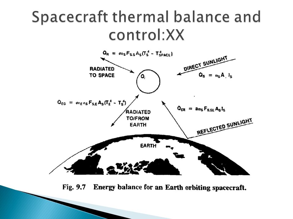
Balance equation for Spacecraft equilibrium temperature is thus constructed: Heat radiated from space = Direct solar input + reflected solar input +Heat radiated from Earth (or nearby body) +Internal heat generation We will start to quantify these in a minute...
 +Internal heat generation We will start to quantify these in a minute...")
53
Heat radiated into space, J, from our Spacecraft. Assume: ◦ Spacecraft is at a temperature, T, and radiates like a blackbody (σT 4 W m -2, σ = Stefan’s constant = 5.670 x 10 -8 J s -1 m -2 K -4 ) ◦ It radiates from it’s entire surface area, A SC – we will ignore the small effect of reabsorption of radiation as our Spacecraft is probably not a regular solid. ◦ Has an emissivity of ε. Therefore: J = A SC εσ T 4
 ◦ It radiates from it’s entire surface area, A SC – we will ignore the small effect of reabsorption of radiation as our Spacecraft is probably not a regular solid. ◦ Has an emissivity of ε. Therefore: J = A SC εσ T 4.")
54
Now we start to quantify the other components. Direct solar input, need: ◦ J S, the solar radiation intensity (ie., the solar constant at 1 AU for our Earth orbiting spacecraft). ◦ A’ S the cross-section area of our spacecraft as seen from the Sun (A’ S ≠ A SC !) ◦ The absorbtivity, α, of our spacecraft for solar radiation (how efficient our spacecraft is at absorbing this energy) ◦ Direct solar input = A’ S α J S
. ◦ A’ S the cross-section area of our spacecraft as seen from the Sun (A’ S ≠ A SC !) ◦ The absorbtivity, α, of our spacecraft for solar radiation (how efficient our spacecraft is at absorbing this energy) ◦ Direct solar input = A’ S α J S.")
55
Reflected solar input. Need: ◦ J S – the solar constant at our nearby body. ◦ A’ P the cross-sectional area of the spacecraft seen from the planet ◦ Absorbtivity, α, for spacecraft of solar radiation ◦ The albedo of the planet, and what fraction, a, of that albedo is being seen by the spacecraft (function of altitude, orbital position etc.) ◦ Define: J a = albedo of planet x J S x a ◦ Reflected solar input = A’ p α J a
 ◦ Define: J a = albedo of planet x J S x a ◦ Reflected solar input = A’ p α J a.")
56
Heat radiated from Earth (nearby body) onto spacecraft. Need: ◦ J p = planet’s own radiation intensity ◦ F 12, a viewing factor between the two bodies. Planet is not a point source at this distance. ◦ A’ P cross-sectional area of spacecraft seen from the planet. ◦ Emissivity, ε, of spacecraft ◦ Heat radiated from Earth onto spacecraft= A’ P ε F 12 J P ◦ Q: Why ε and not α? α is wavelength (i.e., temperature) dependent. Planet is cooler than Sun and at low temperature α = ε) Spacecraft internally generated heat = Q
 dependent. Planet is cooler than Sun and at low temperature α = ε) Spacecraft internally generated heat = Q.")
57
So, putting it all together... Divide by A SC ε (and tidy) to get: Therefore α/ε term is clearly important.
 to get: Therefore α/ε term is clearly important..")
58
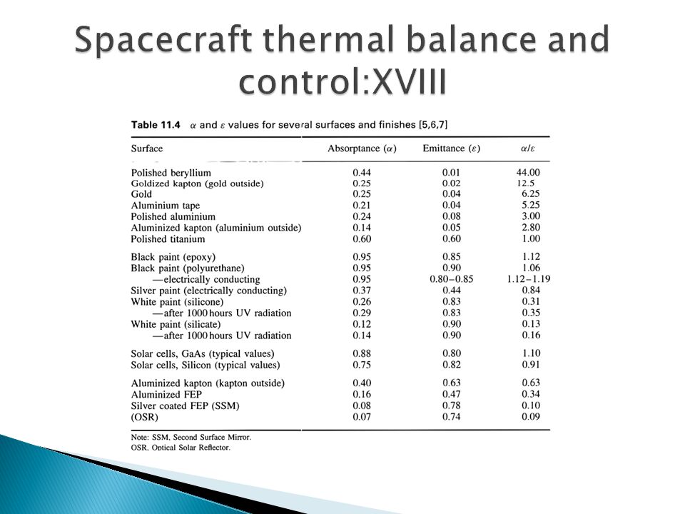
Of the other terms, J S, J a, J P and Q are critical in determining spacecraft temperature. Q: How can we control T? (for a given spacecraft). ◦ In a fixed orbit J S, J a, J P are all fixed. ◦ Could control Q ◦ Could control α/ε (simply paint it!) So select α/ε when making spacecraft. Table on next slide gives some values of α/ε.
. ◦ In a fixed orbit J S, J a, J P are all fixed. ◦ Could control Q ◦ Could control α/ε (simply paint it!) So select α/ε when making spacecraft. Table on next slide gives some values of α/ε..")
61
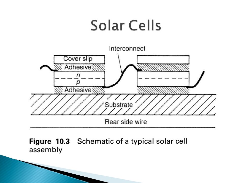
These use solar radiant energy and convert it directly into electricity, via the photovoltaic effect. An array is made up of thousands of individual cells (2 cm x 4 cm typically), connected in series to provide DC power (28 V typical, 120 V can be found today). Power levels can be in range of a few Watts to 100’s of kW. An individual cell is just a semiconductor p-n junction.
, connected in series to provide DC power (28 V typical, 120 V can be found today). Power levels can be in range of a few Watts to 100’s of kW. An individual cell is just a semiconductor p-n junction..")
63
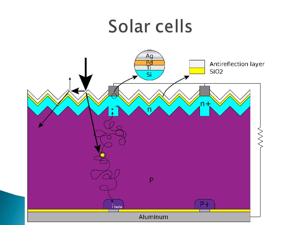
Silicon was typical, today (Gallium Arsenide) GaAs has been used but is not universal. Silicon is doped with boron to produce p-type (electron deficient) material and phosphorous for n-type (electron excess) material. In dark conditions an equilibrium is reached where no significant current flows. If illuminated, by photons of sufficient energy, electron-hole pairs are created, these flow creating a potential difference across the device.
 material and phosphorous for n-type (electron excess) material. In dark conditions an equilibrium is reached where no significant current flows. If illuminated, by photons of sufficient energy, electron-hole pairs are created, these flow creating a potential difference across the device..")
65
To cause the hole-electron production the photon energy has to exceed the band-gap energy. If photons have excess energy this can be deposited as heat. We can define hf E g where h is Planck’s constant, f is the frequency of the radiation and E g is the band gap in Joules. You can characterise a solar cell by its I-V curve. The best operating point is the maximum power point, given by V mp and I mp

66
You can also define: ◦ Open circuit voltage (i.e. no current drawn) V oc ◦ Short circuit current I sc ◦ A fill factor (FF) which says how “square” the I-V curve is. The “squarer” the better. FF is defined as: FF = (V mp I mp )/(V oc I sc ) The closer to 1 this is the “squarer” it is.
 V oc ◦ Short circuit current I sc ◦ A fill factor (FF) which says how square the I-V curve is. The squarer the better. FF is defined as: FF = (V mp I mp )/(V oc I sc ) The closer to 1 this is the squarer it is..")
67
For a silicon cell V oc is typically 0.5 to 0.6 V, I sc depends on the illumination level, and FF can be 0.7 to 0.85. To find the peak power, you draw output power vs. output voltage. A clear peak can be found, which defines V mp and hence I mp can be determined. If you heat a solar cell you will find its performance changes. Its efficiency falls as its temperature increases.

68
There is a packing factor for a solar panel, which describes how much of its surface area is really solar cells, 0.9 is good. The rest is structure, edges, gaps etc. So the effective area is less than the actual surface area of a solar panel. Solar panels need to be face on to the Sun for maximum efficiency. If they are tilted then a geometric correction has to be applied to give the cross-section projected orthogonal to the solar direction. If the angle between the normal to the surface of the panel and the solar direction is θ, then there is a factor cos θ that has to be applied when finding the effective surface area illuminated and hence the power output.

69
Solar cells in orbit do suffer degradation with time. Due to: ◦ Accumulation of micrometeorite impact damage, ◦ Attack by atomic oxygen on the wiring ◦ Radiation damage to the semi-conductor. There is thus a factor for loss of efficiency with time – power output falls slowly with time. Estimating this loss rate, and over-sizing the solar array at the Beginning of Life (BOL) so it over-produces power but produces the correct power at the End of Life (EOL). Solar panels at the BOL in Earth orbit can produce 30 – 50 Watts per kg of mass. Current state-of-the-art Multi-Junction (MJ) solar cells have efficiencies approaching 50%.
 so it over-produces power but produces the correct power at the End of Life (EOL). Solar panels at the BOL in Earth orbit can produce 30 – 50 Watts per kg of mass. Current state-of-the-art Multi-Junction (MJ) solar cells have efficiencies approaching 50%..")
70
A practical device is shown in F&S page 340

71
IsotopeFuel formDecay product Power density (W/g) τ ½ (years) Polonium 210Gd Poα820.38 Plutonium 238Pu O 2 α0.4186.4 Curium 242Cm 2 O 3 α980.4 Strontium 90SrOβ0.2428.0 Various radioactive materials for possible use in a RTG.
 τ ½ (years) Polonium 210Gd Poα Plutonium 238Pu O 2 α Curium 242Cm 2 O 3 α980.4 Strontium 90SrOβ Various radioactive materials for possible use in a RTG.")
72
Pellet of glowing 238 PuO 2 – generating 62 watts of heat

73
Cassini RTG – source, NASA

74
When considering a design, care has to be made to ensure that in the event of an accident during launch, the radioactive material does not escape into the environment. Clean-up costs would be expensive in terms of money, and public support! The power generated by a RTG is not constant with time, the material decays so there is less as time goes on and hence less power can be generated.

75
Much better…..New Horizons’ RTG (mission to Pluto) [Cassini flight spare, using 11 kg of Plutonium pellets]
![Much better…..New Horizons’ RTG (mission to Pluto) [Cassini flight spare, using 11 kg of Plutonium pellets]](http://images.slideplayer.com/15/4850079/slides/slide_75.jpg "Much better…..New Horizons’ RTG (mission to Pluto) [Cassini flight spare, using 11 kg of Plutonium pellets]")
76
When considering a design, care has to be made to ensure that in the event of an accident during launch, the radioactive material does not escape into the environment. Clean-up costs would be expensive in terms of money, and public support! The power generated by a RTG is not constant with time, the material decays so there is less as time goes on and hence less power can be generated.

77
You need: Where P t is power at time t, and P 0 is the initial power at t = 0. τ ½ (years) is given in the table above.
 is given in the table above..")
78
You need: Where P t is power at time t, and P 0 is the initial power at t = 0. τ ½ (years) is given in the table above.
 is given in the table above..")
79
So you have to calculate what power you need for the mission and start the mission (Beginning Of Life - BOL) with too much power. Then as the source decays, the RTG’s output falls and you plan it so you have just the right amount of power at the end of the mission lifetime (End Of Life – EOL)
.")
81
Derivation of the rocket equation WITH and WITHOUT gravity. How to break the equation up into P, S and R and apply that to multi-staging. Understand and use the drag force equation Calculate the solar constant and understand that the radiation intensity falls off as 1/r 2. Be able to describe in broad terms the different phases of a mission, from concept phase through to end-of-life phase.

82
Why thermal control is vital to spacecraft operations How to calculate the equilibrium temperature of spacecraft given it’s emittance, absorptance, distance from the Sun and it’s orbital parameters. Using energy balance arguments derive a mathematical expression for the temperature of a spacecraft.

83
What the main drivers and constraints are in designing and implementing a space mission. Be able to describe the three main power sources used by spacecraft and how each works. What the approximate power output is (as a function of weight) for each of the power sources The advantages and disadvantages of each power source.
 for each of the power sources The advantages and disadvantages of each power source..")
84
How a Spacecraft’s eventual operational environments (NEO, deep space etc.) determines the materials from which it is constructed. What materials are generally used in spacecraft construction Know the meaning of: ◦ Apogee ◦ Perigee ◦ Albedo ◦ Absorptance ◦ Emittance

Similar presentations


 m s2 = 35 tons“ m s3 = 10 tons“ m f1 = 2160 tons“>")


 Recap: Orbital Velocity M = planet’s mass m = satellite’s mass r MG v or >")


 2 nd Homework due TODAY IN-CLASS QUIZ NEXT FRIDAY!! The Sun Today A100 Solar System.>")