Download presentation
Presentation is loading. Please wait.

1
University of British Columbia CPSC 314 Computer Graphics May-June 2005 Tamara Munzner http://www.ugrad.cs.ubc.ca/~cs314/Vmay2005 Viewing, Projections I/II Week 2, Tue May 17

2
2 News extra lab coverage with TAs 12-2 Mondays, Wednesdays for rest of term just for answering questions, no presentations

3
3 Reading: Today FCG Chapter 6 FCG Section 5.3.1 RB rest of Chap Viewing RB rest of App Homogeneous Coords

4
4 Reading: Next Time FCG Section 2.11 FCG Chap 3 except 3.8 FCG Chap 17 Human Vision (pp 293-298) FCG Chap 18 Color pp 301-311 until Section 18.9 Tone Mapping
 FCG Chap 18 Color pp until Section 18.9 Tone Mapping")
5
5 Textbook Errata list at http://www.cs.utah.edu/~shirley/fcg/errata http://www.cs.utah.edu/~shirley/fcg/errata p 113 last matrix, last column denominators D-a -> A-a E-b -> B-b F-c -> C-c p 120 "Sometimes we will want to take the inverse of P" should be "M_p" instead of "P"

6
6 Correction 2 : Vector-Vector Subtraction subtract: vector - vector = vector argument reversal 2

7
7 Review: 2D Rotation (x, y) (x′, y′) x ′ = x cos( ) - y sin( ) y ′ = x sin( ) + y cos( ) counterclockwise, RHS
 (x′, y′) x ′ = x cos( ) - y sin( ) y ′ = x sin( ) + y cos( ) counterclockwise, RHS")
8
8 Review: 2D Rotation From Trig Identities x = r cos ( ) y = r sin ( ) x′ = r cos ( + ) y′ = r sin ( + ) Trig Identity… x′ = r cos( ) cos( ) – r sin( ) sin( ) y′ = r sin( ) cos( ) + r cos( ) sin( ) Substitute… x ′ = x cos( ) - y sin( ) y ′ = x sin( ) + y cos( ) (x, y) (x′, y′)
 y = r sin ( ) x′ = r cos ( + ) y′ = r sin ( + ) Trig Identity… x′ = r cos( ) cos( ) – r sin( ) sin( ) y′ = r sin( ) cos( ) + r cos( ) sin( ) Substitute… x ′ = x cos( ) - y sin( ) y ′ = x sin( ) + y cos( ) (x, y) (x′, y′) ")
9
9 Review: 2D Rotation: Another Derivation x x ' B A (x′,y′) (x,y) x
 (x,y) x")
10
10 Review: Shear, Reflection shear along x axis push points to right in proportion to height reflect across x axis mirror x y x y x x

11
11 Review: 2D Transformations scaling matrixrotation matrix translation multiplication matrix?? vector addition matrix multiplication (x,y) (x′,y′)
 (x′,y′).")
12
12 Review: Linear Transformations linear transformations are combinations of shear scale rotate reflect properties of linear transformations satisifes T(sx+ty) = s T(x) + t T(y) origin maps to origin lines map to lines parallel lines remain parallel ratios are preserved closed under composition
 = s T(x) + t T(y) origin maps to origin lines map to lines parallel lines remain parallel ratios are preserved closed under composition")
13
13 Review: Homogeneous Coordinates Geometrically point in 2D cartesian + weight w = point P in 3D homog. coords multiples of (x,y,w) all homogeneous points on 3D line L represent same 2D cartesian point homogenize to convert homog. 3D point to cartesian 2D point divide by w to get (x/w, y/w, 1) w=0 is direction; (0,0,0) is undefined homogeneouscartesian / w x y w w=1
 all homogeneous points on 3D line L represent same 2D cartesian point homogenize to convert homog. 3D point to cartesian 2D point divide by w to get (x/w, y/w, 1) w=0 is direction; (0,0,0) is undefined homogeneouscartesian / w x y w w=1.")
14
14 Review: 3D Homog Transformations use 4x4 matrices for 3D transformationstranslate(a,b,c) scale(a,b,c)
 scale(a,b,c)")
15
15 Review: Affine Transformations affine transforms are combinations of linear transformations translations properties of affine transformations origin does not necessarily map to origin lines map to lines parallel lines remain parallel ratios are preserved closed under composition

16
16 Review: Composing Transformations Ta Tb = Tb Ta, but Ra Rb != Rb Ra and Ta Rb != Rb Ta

17
17 Review: Composing Transforms order matters 4x4 matrix multiplication not commutative! moving to origin transformation of geometry into coordinate system where operation becomes simpler perform operation transform geometry back to original coordinate system

18
18 Review: Composing Transformations which direction to read? right to left interpret operations wrt fixed coordinates moving object left to right interpret operations wrt local coordinates changing coordinate system OpenGL updates current matrix with postmultiply glTranslatef(2,3,0); glRotatef(-90,0,0,1); glVertexf(1,1,1); specify vector last, in final coordinate system first matrix to affect it is specified second-to-last OpenGL pipeline ordering!
; glRotatef(-90,0,0,1); glVertexf(1,1,1); specify vector last, in final coordinate system first matrix to affect it is specified second-to-last OpenGL pipeline ordering!.")
19
Review: Arbitrary Rotation problem: given two orthonormal coordinate systems XYZ and UVW find transformation from one to the other answer: transformation matrix R whose columns are U,V,W: Y Z X W V U

20
20 (2,1) (1,1) left to right: changing coordinate system right to left: moving object translate by (-1,0) Review: Interpreting Transformations same relative position between object and basis vectors intuitive? OpenGL

21
21 Review: Transformation Hierarchies transforms apply to graph nodes beneath them design structure so that object doesn’t fall apart instancing

22
22 glPushMatrix() glPopMatrix() A B C A B C A B C C glScale3f(2,2,2) D = C scale(2,2,2) trans(1,0,0) A B C D DrawSquare() glTranslate3f(1,0,0) DrawSquare() Review: Matrix Stacks OpenGL matrix calls postmultiply matrix M onto current matrix P, overwrite it to be PM or can save intermediate states with stack no need to compute inverse matrices all the time modularize changes to pipeline state avoids accumulation of numerical errors
 glPopMatrix() A B C A B C A B C C glScale3f(2,2,2) D = C scale(2,2,2) trans(1,0,0) A B C D DrawSquare() glTranslate3f(1,0,0) DrawSquare() Review: Matrix Stacks OpenGL matrix calls postmultiply matrix M onto current matrix P, overwrite it to be PM or can save intermediate states with stack no need to compute inverse matrices all the time modularize changes to pipeline state avoids accumulation of numerical errors")
23
23 Review: Transforming Normals shear, nonuniform scale makes normal nonperpendicular need to use inverse transpose matrix instead

24
24 Review: Display Lists precompile/cache block of OpenGL code for reuse efficiency exact optimizations depend on driver multiple instances of same object static objects redrawn often exploit hierarchical structure when possible set up list once with glNewList/glEndList call multiple times

25
25 Viewing

26
26 Using Transformations three ways modelling transforms place objects within scene (shared world) viewing transforms place camera projection transforms change type of camera
 viewing transforms place camera projection transforms change type of camera")
27
27 Viewing and Projection need to get from 3D world to 2D image projection: geometric abstraction what eyes or cameras do two pieces viewing transform: where is the camera, what is it pointing at? perspective transform: 3D to 2D flatten to image

28
28 Rendering Pipeline GeometryDatabaseGeometryDatabase Model/ViewTransform.Model/ViewTransform. LightingLightingPerspectiveTransform.PerspectiveTransform. ClippingClipping ScanConversionScanConversion DepthTestDepthTest TexturingTexturing BlendingBlending Frame-bufferFrame-buffer

29
29 Rendering Pipeline GeometryDatabaseGeometryDatabase Model/ViewTransform.Model/ViewTransform. LightingLightingPerspectiveTransform.PerspectiveTransform. ClippingClipping ScanConversionScanConversion DepthTestDepthTest TexturingTexturing BlendingBlending Frame-bufferFrame-buffer

30
30 Rendering Pipeline Scene graph Object geometry Modelling Transforms Viewing Transform Projection Transform

31
31 result all vertices of scene in shared 3D world coordinate system Scene graph Object geometry Modelling Transforms Viewing Transform Projection Transform Rendering Pipeline

32
32 result scene vertices in 3D view (camera) coordinate system Scene graph Object geometry Modelling Transforms Viewing Transform Projection Transform Rendering Pipeline
 coordinate system Scene graph Object geometry Modelling Transforms Viewing Transform Projection Transform Rendering Pipeline")
33
33 result 2D screen coordinates of clipped vertices Scene graph Object geometry Modelling Transforms Viewing Transform Projection Transform Rendering Pipeline

34
34 Coordinate Systems result of a transformation names convenience giraffe: neck, head, tail standard conventions in graphics pipeline object/modelling world camera/viewing/eye screen/window raster/device

35
35 Projective Rendering Pipeline OCS - object/model coordinate system WCS - world coordinate system VCS - viewing/camera/eye coordinate system CCS - clipping coordinate system NDCS - normalized device coordinate system DCS - device/display/screen coordinate system OCS O2W VCS CCS NDCS DCSmodelingtransformationviewingtransformation projectiontransformation viewporttransformation perspective divide objectworld viewing device normalized device clipping W2VV2C N2D C2N WCS

36
36 Basic Viewing starting spot - OpenGL camera at world origin probably inside an object y axis is up looking down negative z axis why? RHS with x horizontal, y vertical, z out of screen translate backward so scene is visible move distance d = focal length can use rotate/translate/scale to move camera demo: Nate Robins tutorial transformations

37
37 Viewing in Project 1 where is camera in template code? 5 units back, looking down -z axis

38
38 Convenient Camera Motion rotate/translate/scale not intuitive arbitrary viewing position eye point, gaze/lookat direction, up vector

39
39 Convenient Camera Motion rotate/translate/scale not intuitive arbitrary viewing position eye point, gaze/lookat direction, up vector Peye Pref up view eye lookat y z x WCS

40
40 From World to View Coordinates: W2V translate eye to origin rotate view vector (lookat – eye) to w axis rotate around w to bring up into vw-plane y z x WCS v u VCS Peye w Pref up view eye lookat
 to w axis rotate around w to bring up into vw-plane y z x WCS v u VCS Peye w Pref up view eye lookat")
41
41 OpenGL Viewing Transformation gluLookAt(ex,ey,ez,lx,ly,lz,ux,uy,uz) postmultiplies current matrix, so to be safe: glMatrixMode(GL_MODELVIEW); glLoadIdentity(); gluLookAt(ex,ey,ez,lx,ly,lz,ux,uy,uz) // now ok to do model transformations demo: Nate Robins tutorial projection
 postmultiplies current matrix, so to be safe: glMatrixMode(GL_MODELVIEW); glLoadIdentity(); gluLookAt(ex,ey,ez,lx,ly,lz,ux,uy,uz) // now ok to do model transformations demo: Nate Robins tutorial projection")
42
42 Deriving W2V Transformation translate eye to origin y z x WCS v u VCS Peye w Pref up view eye lookat

43
43 Deriving W2V Transformation rotate view vector (lookat – eye) to w axis w is just opposite of view/gaze vector g y z x WCS v u VCS Peye w Pref up view eye lookat
 to w axis w is just opposite of view/gaze vector g y z x WCS v u VCS Peye w Pref up view eye lookat")
44
44 Deriving W2V Transformation rotate around w to bring up into vw -plane u should be perpendicular to vw-plane, thus perpendicular to w and up vector t v should be perpendicular to u and w y z x WCS v u VCS Peye w Pref up view eye lookat

45
45 Deriving W2V Transformation rotate from WCS xyz into uvw coordinate system with matrix that has rows u, v, w reminder: rotate from uvw to xyz coord sys with matrix M that has columns u,v,w rotate from xyz coord sys to uvw coord sys with matrix M T that has rows u,v,w

46
46 Deriving W2V Transformation M=RT

47
47 Moving the Camera or the World? two equivalent operations move camera one way vs. move world other way example initial OpenGL camera: at origin, looking along -z axis create a unit square parallel to camera at z = -10 translate in z by 3 possible in two ways camera moves to z = -3 Note OpenGL models viewing in left-hand coordinates camera stays put, but square moves to -7 resulting image same either way possible difference: are lights specified in world or view coordinates?

48
48 World vs. Camera Coordinates W a = (1,1) W a b = (1,1) C1 = (3,2) W c = (1,1) C2 = (1,3) C1 = (4,4) W C1 b C2 c
 W a b = (1,1) C1 = (3,2) W c = (1,1) C2 = (1,3) C1 = (4,4) W C1 b C2 c.")
49
49 Projections I

50
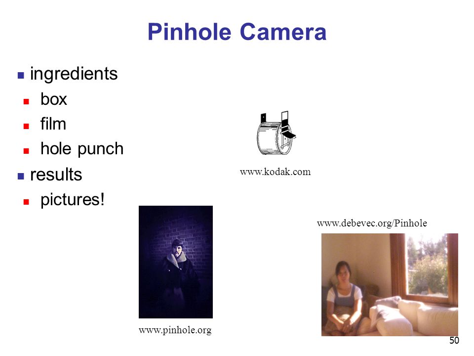
50 Pinhole Camera ingredients box film hole punch results pictures! www.kodak.com www.pinhole.org www.debevec.org/Pinhole
51
51 Pinhole Camera theoretical perfect pinhole film plane pinhole one ray of projection

52
52 Pinhole Camera non-zero sized hole film plane pinhole multiple rays of projection

53
53 Pinhole Camera field of view and focal length film plane field of view pinhole focal length

54
54 Pinhole Camera field of view and focal length film plane field of view pinhole focal length

55
55 Real Cameras real pinhole camera aperture flens camera price to pay: limited depth of field pinhole camera has small aperture (lens opening) hard to get enough light to expose the film lens permits larger apertures lens permits changing distance to film plane without actually moving the film plane
 hard to get enough light to expose the film lens permits larger apertures lens permits changing distance to film plane without actually moving the film plane")
56
56 Graphics Cameras real pinhole camera: image inverted imageplane eye point point computer graphics camera: convenient equivalent imageplane eye point point center of projection

57
57 General Projection image plane need not be perpendicular to view plane imageplane eye point point imageplane eye

58
58 Perspective Projection our camera must model perspective

59
59 Perspective Projection our camera must model perspective

60
60 Perspective Projection our camera must model perspective

61
61 Perspective Projections one-pointperspective two-pointperspective three-pointperspective classified by vanishing points

62
62 Projective Transformations planar geometric projections planar: onto a plane geometric: using straight lines projections: 3D -> 2D aka projective mappings counterexamples?

63
63 Projective Transformations properties lines mapped to lines and triangles to triangles parallel lines do NOT remain parallel e.g. rails vanishing at infinity affine combinations are NOT preserved e.g. center of a line does not map to center of projected line (perspective foreshortening)
.")
64
64 Perspective Projection project all geometry through common center of projection (eye point) onto an image plane x z x z y x -z
 onto an image plane x z x z y x -z")
65
65 Perspective Projection how tall should this bunny be? COP projection plane

66
66 Basic Perspective Projection similar triangles z P(x,y,z) P(x’,y’,z’) z’=d y nonuniform foreshortening not affine but
 P(x’,y’,z’) z’=d y nonuniform foreshortening not affine but")
67
67 Perspective Projection desired result for a point [x, y, z, 1] T projected onto the view plane: what could a matrix look like to do this?
![67 Perspective Projection desired result for a point [x, y, z, 1] T projected onto the view plane: what could a matrix look like to do this](http://images.slideplayer.com/15/4830467/slides/slide_67.jpg "67 Perspective Projection desired result for a point [x, y, z, 1] T projected onto the view plane: what could a matrix look like to do this")
68
68 Simple Perspective Projection Matrix

69
69 Simple Perspective Projection Matrix is homogenized version of where w = z/d

70
70 Simple Perspective Projection Matrix is homogenized version of where w = z/d

71
71 Perspective Projection expressible with 4x4 homogeneous matrix use previously untouched bottom row perspective projection is irreversible many 3D points can be mapped to same (x, y, d) on the projection plane no way to retrieve the unique z values
 on the projection plane no way to retrieve the unique z values")
72
72 Moving COP to Infinity as COP moves away, lines approach parallel when COP at infinity, orthographic view

73
73 Orthographic Camera Projection camera’s back plane parallel to lens infinite focal length no perspective convergence just throw away z values

74
74 Perspective to Orthographic transformation of space center of projection moves to infinity view volume transformed from frustum (truncated pyramid) to parallelepiped (box) -z x -z x Frustum Parallelepiped
 to parallelepiped (box) -z x -z x Frustum Parallelepiped")
75
75 View Volumes specifies field-of-view, used for clipping restricts domain of z stored for visibility test z perspective view volume orthographic view volume x=left x=right y=top y=bottom z=-near z=-far x VCS x z y y x=left y=top x=right z=-far z=-near y=bottom

76
76 View Volume convention viewing frustum mapped to specific parallelepiped Normalized Device Coordinates (NDC) same as clipping coords only objects inside the parallelepiped get rendered which parallelepiped? depends on rendering system

77
77 Normalized Device Coordinates left/right x =+/- 1, top/bottom y =+/- 1, near/far z =+/- 1 -z x Frustum z=-n z=-f right left z x x= -1 z=1 x=1 Camera coordinates NDC z= -1

78
78 Understanding Z z axis flip changes coord system handedness RHS before projection (eye/view coords) LHS after projection (clip, norm device coords) x z VCS y x=left y=top x=right z=-far z=-near y=bottom x z NDCS y (-1,-1,-1) (1,1,1)
 LHS after projection (clip, norm device coords) x z VCS y x=left y=top x=right z=-far z=-near y=bottom x z NDCS y (-1,-1,-1) (1,1,1)")
79
79 Understanding Z near, far always positive in OpenGL calls glOrtho(left,right,bot,top,near,far); glOrtho(left,right,bot,top,near,far); glFrustum(left,right,bot,top,near,far); glFrustum(left,right,bot,top,near,far); glPerspective(fovy,aspect,near,far); glPerspective(fovy,aspect,near,far); orthographic view volume x z VCS y x=left y=top x=right z=-far z=-near y=bottom perspective view volume x=left x=right y=top y=bottom z=-near z=-far x VCS y
; glOrtho(left,right,bot,top,near,far); glFrustum(left,right,bot,top,near,far); glFrustum(left,right,bot,top,near,far); glPerspective(fovy,aspect,near,far); glPerspective(fovy,aspect,near,far); orthographic view volume x z VCS y x=left y=top x=right z=-far z=-near y=bottom perspective view volume x=left x=right y=top y=bottom z=-near z=-far x VCS y")
80
80 Understanding Z why near and far plane? near plane: avoid singularity (division by zero, or very small numbers) far plane: store depth in fixed-point representation (integer), thus have to have fixed range of values (0…1) avoid/reduce numerical precision artifacts for distant objects
 far plane: store depth in fixed-point representation (integer), thus have to have fixed range of values (0…1) avoid/reduce numerical precision artifacts for distant objects.")
81
81 Orthographic Derivation scale, translate, reflect for new coord sys x z VCS y x=left y=top x=right z=-far z=-near y=bottom x z NDCS y (-1,-1,-1) (1,1,1)
 (1,1,1)")
82
82 Orthographic Derivation scale, translate, reflect for new coord sys x z VCS y x=left y=top x=right z=-far z=-near y=bottom x z NDCS y (-1,-1,-1) (1,1,1)
 (1,1,1)")
83
83 Orthographic Derivation scale, translate, reflect for new coord sys

84
84 Orthographic Derivation scale, translate, reflect for new coord sys x z VCS y x=left y=top x=right z=-far z=-near y=bottom same idea for right/left, far/near

85
85 Orthographic Derivation scale, translate, reflect for new coord sys

86
86 Orthographic Derivation scale, translate, reflect for new coord sys

87
87 Orthographic Derivation scale, translate, reflect for new coord sys

88
88 Orthographic Derivation scale, translate, reflect for new coord sys

89
89 Orthographic OpenGL glMatrixMode(GL_PROJECTION);glLoadIdentity();glOrtho(left,right,bot,top,near,far);
;glLoadIdentity();glOrtho(left,right,bot,top,near,far);")
90
90 Projections II

91
91 NDC to Viewport Transformation generate pixel coordinates map x, y from range –1…1 (NDC) to pixel coordinates on the display involves 2D scaling and translation x y display viewport
 to pixel coordinates on the display involves 2D scaling and translation x y display viewport")
92
92 NDC to Viewport Transformation (-1,-1) (1,1) (0,0) (w,h) NDCS DCS glViewport(x,y,a,b); default : a b x y glViewport(0,0,w,h); OpenGL 2D scaling and translation
 (1,1) (0,0) (w,h) NDCS DCS glViewport(x,y,a,b); default : a b x y glViewport(0,0,w,h); OpenGL 2D scaling and translation")
93
93 Origin Location yet more possibly confusing conventions OpenGL: lower left most window systems: upper left often have to flip your y coordinates when interpreting mouse position

94
94 Perspective Example tracks in VCS: left x=-1, y=-1 right x=1, y=-1 view volume left = -1, right = 1 bot = -1, top = 1 near = 1, far = 4 z=-1 z=-4 x z VCS top view 1 1 NDCS (z not shown) real midpoint 0 xmax-1 0 DCS (z not shown) ymax-1 x=-1 x=1
 real midpoint 0 xmax-1 0 DCS (z not shown) ymax-1 x=-1 x=1")
95
95 Viewing Transformation OCS WCS VCSmodelingtransformationviewingtransformation OpenGL ModelView matrix objectworld viewing y x VCS Peye z y x WCS y z OCS image plane

96
96 Projective Rendering Pipeline OCS - object/model coordinate system WCS - world coordinate system VCS - viewing/camera/eye coordinate system CCS - clipping coordinate system NDCS - normalized device coordinate system DCS - device/display/screen coordinate system OCS O2W VCS CCS NDCS DCSmodelingtransformationviewingtransformation projectiontransformation viewporttransformation perspective divide objectworld viewing device normalized device clipping W2VV2C N2D C2N WCS

97
97 Perspective Projection specific example assume image plane at z = -1 a point [x,y,z,1] T projects to [-x/z,-y/z,-z/z,1] T [x,y,z,-z] T -z
![97 Perspective Projection specific example assume image plane at z = -1 a point [x,y,z,1] T projects to [-x/z,-y/z,-z/z,1] T [x,y,z,-z] T -z](http://images.slideplayer.com/15/4830467/slides/slide_97.jpg "97 Perspective Projection specific example assume image plane at z = -1 a point [x,y,z,1] T projects to [-x/z,-y/z,-z/z,1] T [x,y,z,-z] T -z")
98
98 Perspective Projection alter w / w projectiontransformation perspectivedivision

99
99 Canonical View Volumes standardized viewing volume representation orthographic perspective orthogonal parallel x or y -z x or y -z 1 Front Plane front plane back plane x or y = +/- z

100
100 Why Canonical View Volumes? permits standardization clipping easier to determine if an arbitrary point is enclosed in volume consider clipping to six arbitrary planes of a viewing volume versus canonical view volume rendering projection and rasterization algorithms can be reused

101
101 Projection Normalization one additional step of standardization warp perspective view volume to orthogonal view volume render all scenes with orthographic projection! x z= z=d x z=0 z=d

102
102 Predistortion

103
103 Perspective Normalization perspective viewing frustum transformed to cube orthographic rendering of cube produces same image as perspective rendering of original frustum

104
104 Demos Tuebingen applets from Frank Hanisch http://www.gris.uni-tuebingen.de/projects/grdev/doc/html/etc/ AppletIndex.html#Transformationen

105
Perspective Warp matrix formulation preserves relative depth (third coordinate) what does mean?
 what does mean")
106
Perspective Warp matrix formulation preserves relative depth (third coordinate) what does mean?
 what does mean")
107
107 Projection Normalization distort such that orthographic projection of distorted objects is desired persp projection separate division from standard matrix multiplies clip after warp, before divide division: normalization CCS NDCS alter w / w VCS projectiontransformation viewing normalized device clipping perspectivedivision V2CC2N

108
108 Projective Rendering Pipeline OCS - object coordinate system WCS - world coordinate system VCS - viewing coordinate system CCS - clipping coordinate system NDCS - normalized device coordinate system DCS - device coordinate system OCS WCS VCS CCS NDCS DCSmodelingtransformationviewingtransformationprojectiontransformationviewporttransformation alter w / w objectworld viewing device normalized device clipping perspectivedivision glVertex3f(x,y,z) glTranslatef(x,y,z)glRotatef(th,x,y,z)....gluLookAt(...) glFrustum(...) glutInitWindowSize(w,h)glViewport(x,y,a,b) O2WW2VV2C N2D C2N
 glTranslatef(x,y,z)glRotatef(th,x,y,z)....gluLookAt(...) glFrustum(...) glutInitWindowSize(w,h)glViewport(x,y,a,b) O2WW2VV2C N2D C2N")
109
109 Coordinate Systems http://www.btinternet.com/~danbgs/perspective/

110
110 Perspective Derivation x z NDCS y (-1,-1,-1) (1,1,1) x=left x=right y=top y=bottom z=-near z=-far x VCS y z
 (1,1,1) x=left x=right y=top y=bottom z=-near z=-far x VCS y z")
111
111 Perspective Derivation earlier: complete: shear, scale, projection-normalization

112
112 Perspective Derivation

113
113 Perspective Derivation similarly for other 5 planes 6 planes, 6 unknowns

114
114 Perspective Example view volume left = -1, right = 1 bot = -1, top = 1 near = 1, far = 4

115
115 Perspective Example / w

116
116 Asymmetric Frusta our formulation allows asymmetry why bother? -z x Frustum right left -z x Frustum z=-n z=-f right left

117
117 Simpler Formulation left, right, bottom, top, near, far nonintuitive often overkill look through window center symmetric frustum constraints left = -right, bottom = -top

118
118 Field-of-View Formulation FOV in one direction + aspect ratio (w/h) determines FOV in other direction also set near, far (reasonably intuitive) -z x Frustum z=-n z=-f fovx/2 fovy/2 h w
 determines FOV in other direction also set near, far (reasonably intuitive) -z x Frustum z=-n z=-f fovx/2 fovy/2 h w")
119
119 Perspective OpenGL glMatrixMode(GL_PROJECTION); glLoadIdentity(); glFrustum(left,right,bot,top,near,far); or glPerspective(fovy,aspect,near,far);
; glLoadIdentity(); glFrustum(left,right,bot,top,near,far); or glPerspective(fovy,aspect,near,far);")
120
120 Demo: Frustum vs. FOV Nate Robins tutorial (take 2): http://www.xmission.com/~nate/tutors.html
:")
121
121 Projection Taxonomy planarprojections perspective:1,2,3-point parallel oblique orthographic cabinet cavalier top,front,side axonometric:isometricdimetrictrimetric http://ceprofs.tamu.edu/tkramer/ENGR%20111/5.1/20

122
122 Perspective Projections one-pointperspective two-pointperspective three-pointperspective classified by vanishing points

123
Parallel Projection projectors are all parallel vs. perspective projectors that converge orthographic: projectors perpendicular to projection plane oblique: projectors not necessarily perpendicular to projection plane ObliqueOrthographic

124
124 Axonometric Projections projectors perpendicular to image plane select axis lengths http://ceprofs.tamu.edu/tkramer/ENGR%20111/5.1/20

125
125 Oblique Projections x y z cavalier d d x y z cabinet d d / 2 projectors oblique to image plane select angle between front and z axis lengths remain constant both have true front view cavalier: distance true cabinet: distance half

126
126 Demos Tuebingen applets from Frank Hanisch http://www.gris.uni-tuebingen.de/projects/grdev/doc/html/etc/ AppletIndex.html#Transformationen

Similar presentations


 CS 184, Lecture 5: Viewing>")


