Download presentation
Presentation is loading. Please wait.

1
Experiment #4 IC Engine

4
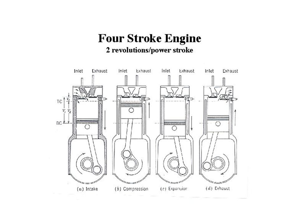
Indicator Diagram expansion ignition compression intake exhaust The indicated work per cycle is computed from the area under the p-v diagram Indicated power = Brake power = indicated power -friction power Pb = Pi-Pf

5
Experimental Apparatus
Controls: Throttle setting Load valve Instrumentation: Engine rpm Dynamometer pressure Fuel flow rate Cylinder head temperature Oil temperature Throttle Engine rpm

6
Objectives Using a single cylinder four stroke engine
Mea sure engine power, rpm and fuel consumption at difference throttle settings Plot relevant engine parameters as a function of engine rpm and discuss the results

7
Engine Parameters Measured Brake power (W):
Brake specific fuel consumption (kg/Nm): Brake mean effective pressure (N/m2): Brake Torque (Nm): Fuel/Air mass ratio Use hp = 0.8
: Brake mean effective pressure (N/m2): Brake Torque (Nm): Fuel/Air mass ratio. Use hp = 0.8.")
8
Engine Parameters (continued)
Volumetric Efficiency = Effects of: air friction chocking backflow, etc hv Engine rpm Conversion Efficiency: Mechanical Efficiency Use HHV = 44 MJ/kg, and

9
Engine Parameters (continued)
where

10
Report PLEASE REPORT YOUR ANSWERS IN SI UNITS
For each throttle setting (1/4,1/2,3/4,full) Compute power, torque,sfc,mep, conversion efficiency Plot these computed quantities against engine rpm Discuss the results using references, and the relationships in the notes Determine the most desirable engine speed for power,torque and efficiency Compare the efficiencies with that of an idea Otto cycle Answer the question on connecting rod stress PLEASE REPORT YOUR ANSWERS IN SI UNITS
 Compute power, torque,sfc,mep, conversion efficiency. Plot these computed quantities against engine rpm. Discuss the results using references, and the relationships in the notes. Determine the most desirable engine speed for power,torque and efficiency. Compare the efficiencies with that of an idea Otto cycle. Answer the question on connecting rod stress. PLEASE REPORT YOUR ANSWERS IN SI UNITS.")
Similar presentations


 Engine Lab Instructor: M>")
 Patel Vidhi A.>")

 engine To determine the effect of load variation at constant speed.>")


