Download presentation
Presentation is loading. Please wait.

1
1 In this lecture, a model based observer and a controller will be designed to a single-link robot.

2
We already designed a model based observer in Lecture 5 for a magnetic levitation train. An observer is designed basically to estimate an unmeasurable state. For example, an induction motor has two unmeasurable states, which are the flux components. Actually there are some flux sensors but they produce noisy and unreliable signals. For this reason, it is better to estimate flux instead of measuring it. Same case occurs in velocity measurement for electrical motor. To get velocity feedback, a control designer can either differentiate the position signal produced by an encoder, or directly use a velocity sensor. Differentiation always leads noisy signal, and velocity sensor does not produce so sensitive and reliable signals. In this lecture we will design an observer to estimate the velocity of the single-link robot manipulator.

3
Remember that we used this maglev train example as a tool to demonstrate an important property of nonlinear systems : Finite Escape Time ! Linear systems has a useful principle named Separation Principle, which means that one can design observer and controller separately for a linear system. If the observer and controller are stable individually, then the overall system is also stable. But this is not the case for nonlinear systems. In a nonlinear system, even if the observer and controller are stable separately, the output of the overall system may escape to infinity in a finite time. We demonstrated it with an example (see the notes of lecture 5). For this reason, we have to take both observer and controller dynamics into account during the stability analysis. We will start with a simple example, and then we will design an observer and a backstepping controller for a single-link robotic manipulator.
. For this reason, we have to take both observer and controller dynamics into account during the stability analysis. We will start with a simple example, and then we will design an observer and a backstepping controller for a single-link robotic manipulator..")
4
Consider a simple two-dimensinoal system in the form of Control objective is to drive x 1 to zero by using the control input signal, u, even though x 2 is not available for measurement. Observer Design Let’s design a model based observer for unmeasurable state: where is the estimation of. Just like the parameter estimation error, we define a state estimation error to quantify the observer performance:

5
Note that Observation Error Dynamics (to be used in composite stability analysis)
")
6
To prove the stability of the observer, following Lyapunov function can be used. Its time derivative is This means that the state estimation error goes to exponentially.

7
Controller Design The term will be used to damp the effect of appears in x 1 dynamics. Damping coefficient

8
Substituting the observer dynamics,, from the designed observer into h dynamics yields Divide both sides of the equation above by ( 1+d 1 ), which is the coefficient of. Design the control input signal as

9
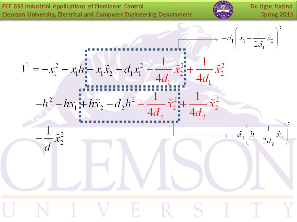
Composite Stability Analysis

11
Select GES !!! ASITCLSAB

12
12 Now we will design an observer for a single-link robot by using the same algorithm. The unmeasurable state is velocity of the robotic arm. As said before, we could get velocity measurement by differentiating the position signal but this would lead a noisy signal. For this reason we will design an observer for velocity.

13
13 The dynamics of an n-link robot manipulator can be written as where Without loss of generality, we consider a single-link (n=1) robot manipulator for simplicity. For a single-link robotic arm, M(q) is the inertia of the arm, H is the viscous friction, and G(q) is the gravitational torque due to weight of the arm.
 is the inertia of the arm, H is the viscous friction, and G(q) is the gravitational torque due to weight of the arm..")
14
14 By selecting the state variables as we get the state-space representation as

15
15 Control objective is to drive x 1 to a desired trajectory, x 1d, by using the control input signal, τ, even though x 2 is not available for measurement. Observer Design Let’s design a model based observer for unmeasurable state: where is the estimation of. Just like the parameter estimation error, we define a state estimation error to quantify the observer performance:

16
Note that Observation Error Dynamics (to be used in composite stability analysis)
")
17
To prove the stability of the observer, following Lyapunov function can be used. Its time derivative is This means that the state estimation error goes to exponentially.

18
Controller Design The term will be used to damp the effect of appears in e dynamics. Damping coefficient

19
Substituting the observer dynamics,, from the designed observer into h dynamics yields Divide both sides of the equation above by ( K e +d 1 ), which is the coefficient of. Design the control input signal as

20
Composite Stability Analysis

22
Select GES !!! ASITCLSAB

23
Linearization Backstepping Adaptive Control Robust Control Observer + Controller (Nonlinear Damping ) (?)
 ( )")
24
Exercise: Can you make this controller adaptive?

Similar presentations


 f(x,u) u x f(x, (x) x. Example: Using feed-forward, what should be canceled?>")


 may be defined as an equation involving one or more derivatives of an.>")


