Download presentation
Presentation is loading. Please wait.

1
Quality of Service (QoS)-Based Management of Preempted Traffic in MPLS Networks Eng. Ayman Maliha Electrical & Computer Engineering Department The Islamic University of Gaza

2
Contents Introduction Preemption in MPLS (MNS-2) Thesis Statement Proposed Preemption Technique Simulation Results Conclusion and Future Work MPLS & Traffic Engineering
 Thesis Statement Proposed Preemption Technique Simulation Results Conclusion and Future Work MPLS & Traffic Engineering")
3
OSI Reference Model Application Presentation Session transport Network Data link Physical Application Presentation Session transport Network Data link Physical Network Data link Physical Source nodeDestination node Intermediate node Signals Packets Bits Frames

4
OSI Reference Model * Functionality: + Implement the desired procedure. + Provide the user interface * end-to-end error recovery and flow control * Provide host to host link * Provide physical connection to the net ROLE * Provides for reliable transfer of information across the physical layer. LAYER 7. Application 4. Transport 3. Network 6. Presentation 5. Session 2. Data Link 1. Physical * Provide enhanced services (Control structure for communication between applications.)
.")
5
OSI Reference Model Source nodeDestination node Application Presentation Session transport Network Data link Physical Application Presentation Session transport Network Data link Physical Network Data link Physical Intermediate node Signals

6
OSI Reference Model AL-Hdr Application Layer Msg PL-HdrPresentation Layer Msg SL-HdrSession Layer Msg TL-HdrTransport Layer Msg NL-HdrNetwork Layer Msg DLL-HdrData Link Layer Msg PL-HdrPhysical Layer Msg Presentation Session Transport Network Data Link Physical Application 7 6 5 4 3 2 1 Network A Node

7
OSI Reference Model Application Presentation Session transport Network Data link Physical Application Presentation Session transport Network Data link Physical Network Data link Physical Source nodeDestination node Intermediate node Signals

8
TCP/IP Reference Model Transport 3. Internet TCP/IP Not Present Application OSI 7. Application 4. Transport 3. Network 6. Presentation 5. Session 2. Data Link 1. Physical 2. Data Link 1. Physical

9
Internet Today Internet today Exceeding the delays and jitter boundaries causes problems to real-time applications. - Provides “best effort” data delivery - Complexity stays in the end-hosts - Network core remains simple - As demands exceed capacity, service degrades gracefully (increased jitter etc.)
.")
10
Quality of Service (QoS) Definition Goal A set of service requirements to be met by the network while transporting a flow. Provide some level of predictability and control beyond the current IP “best-effort” service.

11
QoS Metrics - Bandwidth - Jitter - Delay (or latency) - Loss rate Vary according to Service Level Agreement (SLA)
 - Loss rate Vary according to Service Level Agreement (SLA)")
12
QoS Protocol Classification QoS can be achieved by : – - Resource reservation (integrated services) – - Prioritization (differentiated services) QoS can be applied : – - Per flow (individual, uni-directional streams) – - Per aggregate (two or more flows having something in common)
 – - Prioritization (differentiated services) QoS can be applied : – - Per flow (individual, uni-directional streams) – - Per aggregate (two or more flows having something in common)")
13
QoS Protocol IETF - Integrated Service (IntServ) - Differentiated Services (DiffServ) - Multi Protocol Labeling Switching (MPLS)
 - Differentiated Services (DiffServ) - Multi Protocol Labeling Switching (MPLS)")
14
Integrated Service (IntServ) Philosophy Behind Routers have to be able to reserve resources to provide special QoS for specific user packet streams. Four components of IntServ Model The signaling protocol (e.g. RSVP) The admission control routine The classifier The packet scheduler
 The admission control routine The classifier The packet scheduler.")
15
IntServ Components

16
Sender sends a PATH Message to the receiver specifying the characteristics of the traffic The receiver responds with a RESV Message to request resources for the flow Every intermediate router along the path can reject or accept the request of the RESV Message The signaling protocol

17
IntServ Components Admission control Decide whether a request for resources can be granted Classifier When a router receives a packet, the classifier will perform classification and put the packet in a specific queue based on the classification result Packet scheduler Schedule the packet accordingly to meet its QoS requirements

18
IntServ Problems Problems – Not scalable Huge storage and processing overhead on the routers The amount of state information increases proportionally with the number of flows – Requirement on routers is high All routers must implement RSVP, admission control, classification, and packet scheduling

19
DiffServ - Description Applied on flow aggregates Services requirements are classified Classification is performed at network ingress points A predefined per-hop behavior (PHB) is applied to every service class Traffic is smoothed according to PHB applied
 is applied to every service class Traffic is smoothed according to PHB applied")
20
DiffServ functional elements edge functions: – packet classification – packet marking – traffic conditioning core functions: – forwarding based on per-hop behavior (PHB) associated with packet’s class
 associated with packet’s class")
21
DiffServ - Traffic Classes

22
DiffServ functional elements packet classification Classifier selects packets based on values in packet header fields and steers packet to appropriate marking function Meter Calculates the traffic level, which is compared against the customer’s contract/Service Level Agreement (SLA) profile.
 profile.")
23
DiffServ functional elements Marker The packets are marked by setting the DS value to a correct codepoint as needed Shaper The shaper Polices traffic by delaying packets as necessary so the that the packet does not exceed the traffic rate specified in the profile for that class

24
DiffServ functional elements Dropper Drops the packets when the rate of packets of a given class exceeds that specified in the profile for that class Per-hop behavior (PHB) defines differences in performance among classes.
 defines differences in performance among classes.")
25
DiffServ - Traffic Classes Two traffic classes are available : – Expeditied Forwarding (EF) Minimizes delay and jitter Provides the highest QoS Traffic that exceeds the traffic profile is discarded – Assured Forwarding (AF) 4 classes, 3 drop-precedences within each class Traffic that exceeds the traffic profile is not delivered with such high probability
 Minimizes delay and jitter Provides the highest QoS Traffic that exceeds the traffic profile is discarded – Assured Forwarding (AF) 4 classes, 3 drop-precedences within each class Traffic that exceeds the traffic profile is not delivered with such high probability")
26
DiffServ - Advantages Advantage – Scalable Edge routers maintain per aggregate state Core routers maintain state only for a few traffic classes – Easy implementation Incremental deployment is possible for Assured Forwarding

27
DiffServ - Disadvantages Disadvantage – Provide weaker service than InteServ – per hop behavior cannot guarantee end-to-end QoS.

28
Multiprotocol Label Switching (MPLS) 3- Multiprotocol Label Switching (MPLS) MPLS is a technology that integrates label-swapping paradigm with network-layer routing within Label Switching Routers (LSRs). It is proposed to be a combination of the better properties of ATM and IP. A short fixed-length “label” results in high-speed switching.

29
MPLS Forwarding: Label Swapping Control: IP Router Software Control: IP Router Software Forwarding: Longest-match Lookup Control: ATM Forum Software Forwarding: Label Swapping IP Router MPLS ATM Switch

30
Contents Introduction Preemption in MPLS (MNS-2) Thesis Statement Proposed Preemption Technique Simulation Results Conclusion and Future Work MPLS & Traffic Engineering
 Thesis Statement Proposed Preemption Technique Simulation Results Conclusion and Future Work MPLS & Traffic Engineering")
31
IP Traditional Routing Choosing the next hop Open Shortest Path First (OSPF) to populate the routing table Route look up based on the IP address Find the next router to which the packet has to be sent Replace the layer 2 address Each router performs these steps
 to populate the routing table Route look up based on the IP address Find the next router to which the packet has to be sent Replace the layer 2 address Each router performs these steps")
32
IP Routing Table 47.1 47.2 47.3 1 2 3 1 2 3 1 2 3 Build IP routing table

33
IP Traditional Routing 47.1 47.2 47.3 IP 47.1.1.1 1 2 3 1 2 1 2 3 Traditional IP forwarding

34
Disadvantages Header analysis performed at each hop Increased demand on routers Utilizes the best available path Some congested links and some underutilized links! Degradation of throughput Long delays More losses No QoS No service differentiation Not possible with connectionless protocols

35
MPLS & Traffic Engineering MPLS Components 1- Label Switching Based Router (LSR & LER) A high-speed router device that participate in the establishment of LSP. 2- Label Switching Path (LSP) A sequence of LSRs that is to be followed by a packet. 3- Labeled Packets A packet into which a label has been encoded.
 A sequence of LSRs that is to be followed by a packet. 3- Labeled Packets A packet into which a label has been encoded..")
36
MPLS & Traffic Engineering - (LSP) 47.1 47.2 47.3 1 2 3 1 2 1 2 3 3 Mapping: 0.40 Request: 47.1 Mapping: 0.50 Request: 47.1
 Mapping: 0.40 Request: 47.1 Mapping: 0.50 Request: 47.1")
37
MPLS & Traffic Engineering - (LSP) 47.1 47.2 47.3 1 2 1 2 3 3 IP 47.1.1.1 1 2 3 MPLS Switching
 IP MPLS Switching")
38
MPLS & Traffic Engineering - (ER-LSP) 47.1 47.2 47.3 1 2 3 1 2 1 2 3 3 IP 47.1.1.1
 IP")
39
MPLS & Traffic Engineering - Labels A short, fixed length identifier (32 bits) Sent with each packet Local between two routers Can have different labels if entering from different routers
 Sent with each packet Local between two routers Can have different labels if entering from different routers")
40
MPLS & Traffic Engineering - Labels ATM: LabelVPI/VCI(w/shim) Frame Relay:LabelDLCI(w/shim) Ethernet:LabelShim PPP:LabelShim
 Frame Relay:LabelDLCI(w/shim) Ethernet:LabelShim PPP:LabelShim")
41
MPLS & Traffic Engineering PPP Header LAN MAC Header ATM Cell Header Layer 3 Header PPP Header Label Layer 3 Header MAC Header Label DATA HEC CLP PTI VCI VPI GFC Label

42
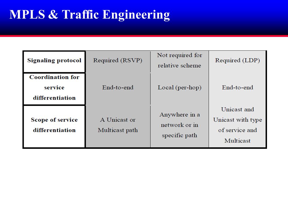
MPLS & Traffic Engineering

45
TE Definition An iterative process of network planning and network optimization TE Objectives - High service quality - Efficiency - Survivability - Cost The established path must fulfill some requirements to deliver the required QoS and it should satisfy the network capacity and policy.

46
MPLS & Traffic Engineering. TE Attributes of Traffic Trunks - Traffic parameter attribute i.e. peak rates, burst size, etc.. - Policing attribute - Path selection and management attribute - Priority attribute - Preemption attribute - Resource attribute

47
Preemption Definition Preemption is the premature suspension or termination of an activity in order to permit some other activity to proceed. Preemption attribute determines whether a traffic trunk can preempt another traffic trunk from a given path. Preemption attribute It is an action that is taken by a system element when the demand for the resources exceeds the available supply.

48
Adaptive Real-time Traffic Adaptive or Controllable real-time applications can adjust their data rates to the available bandwidth e.g. videoconferencing (CIF, MPEG-I). Such applications could be treated at lower QoS level that depends on the available bandwidth.
. Such applications could be treated at lower QoS level that depends on the available bandwidth..")
49
Contents Thesis Statement Introduction Preemption in MPLS (MNS-2) Proposed Preemption Technique Simulation Results Conclusion and Future Work MPLS & Traffic Engineering
 Proposed Preemption Technique Simulation Results Conclusion and Future Work MPLS & Traffic Engineering")
50
Thesis Statement Bandwidth allocation is an important issue in network management dealing with guaranteed bandwidth policy. The ability of an application to maintain its bandwidth depends on its precedence attribute within the network. Preemption allows guaranteed bandwidth for high priority traffic. Harsh solution for the preempted traffic, which loses its resources.

51
Thesis Statement Real-time traffic Advantageous for the preemptor traffic. Disastrous for the preempted traffic Upon preemption, network needs to consider: Reservable bandwidth traffic type priority Adaptive real-time traffic needs to be treated differently when preempted i.e. serving it at lower bit rate if the reservable bandwidth meets the new rate.

52
Contents Preemption in MPLS (MNS-2) Thesis Statement Introduction Proposed Preemption Technique Simulation Results Conclusion and Future Work MPLS & Traffic Engineering
 Thesis Statement Introduction Proposed Preemption Technique Simulation Results Conclusion and Future Work MPLS & Traffic Engineering")
53
MNS Simulator A simulation tool for MPLS network. It is implemented as an extension of NS-2 simulator, which is an object-oriented Tcl script interpreter. MNS-2 commands must be written in a Tcl script file, which defines the simulation scenario.

54
Preemption in MPLS Total link BW (1Mbps) Time Best-effort and signaling traffic (200 kbps) Maximum Real-time bw fraction 800 (kbps) Bandwidth allocation in MNS-2 CR-LSP1 300 (kbps) CR-LSP2 400 (kbps) Reservable bandwidth
 Time Best-effort and signaling traffic (200 kbps) Maximum Real-time bw fraction 800 (kbps) Bandwidth allocation in MNS-2 CR-LSP1 300 (kbps) CR-LSP2 400 (kbps) Reservable bandwidth")
55
Preemption in MPLS Total link BW (1Mbps) Time Best-effort and signaling traffic (200 kbps) Bandwidth allocation for AD-RT in MNS-2 Reservable bandwidth (32 kbps) Real-time bandwidth fraction (800 kbps) CR-LSP1, bw 768 kbps setupPrio 5, holdprio 4. CR-LSP1 768 (kbps) CR-LSP2, bw 400 kbps setupPrio 3, holdprio 2. CR-LSP2 (400 kbps) CR-LSP1 768 (kbps)
 CR-LSP2, bw 400 kbps setupPrio 3, holdprio 2. CR-LSP2 (400 kbps) CR-LSP1 768 (kbps).")
56
Preemption in MPLS Preempted traffic is served at best-effort level, and it becomes under the mercy of network load. Real-time bandwidth fraction is not well utilized. Preempted real-time traffic sharing other best- effort traffic resources, i.e. no dedicated resources remain for the preempted traffic.

57
Contents Proposed Preemption Technique Preemption in MPLS (MNS-2) Thesis Statement Introduction Simulation Results Conclusion and Future Work MPLS & Traffic Engineering
 Thesis Statement Introduction Simulation Results Conclusion and Future Work MPLS & Traffic Engineering")
58
Proposed Preemption Technique Total link BW (1Mbps) Time Best-effort and signaling traffic (200 kbps) Bandwidth allocation for AD-RT in the proposed preemption mechanism. Reservable bandwidth (32 kbps) Real-time bandwidth fraction (800 kbps) CR-LSP1, bw 768 kbps setupPrio 5, holdprio 4. CR-LSP1 768 (kbps) CR-LSP2, bw 400 kbps setupPrio 3, holdprio 2. CR-LSP2 (400 kbps) CR-LSP1 (384 kbps) CR-LSP1 (786 kbps) reservable bw (16 kbps) t Preemption time
 Real-time bandwidth fraction (800 kbps) CR-LSP1, bw 768 kbps setupPrio 5, holdprio 4. CR-LSP1 768 (kbps) CR-LSP2, bw 400 kbps setupPrio 3, holdprio 2. CR-LSP2 (400 kbps) CR-LSP1 (384 kbps) CR-LSP1 (786 kbps) reservable bw (16 kbps) t Preemption time.")
59
Proposed Preemption Technique Total link BW (1Mbps) Time Best-effort and signaling traffic (200 kbps) Bandwidth allocation for AC-RT in the proposed preemption mechanism. Reservable bandwidth (300 kbps) Real-time bandwidth fraction (800 kbps) CR-LSP1, bw 500 kbps setupPrio 5, holdprio 4. CR-LSP1 500 (kbps) CR-LSP2, bw 400 kbps setupPrio 3, holdprio 2. No reservable bw CR-LSP2 (400 kbps) CR-LSP1 (400 kbps) Reservable bandwidth t Preemption time
 Real-time bandwidth fraction (800 kbps) CR-LSP1, bw 500 kbps setupPrio 5, holdprio 4. CR-LSP1 500 (kbps) CR-LSP2, bw 400 kbps setupPrio 3, holdprio 2. No reservable bw CR-LSP2 (400 kbps) CR-LSP1 (400 kbps) Reservable bandwidth t Preemption time.")
60
Contents Simulation Results Proposed Preemption Technique Preemption in MPLS (MNS-2) Thesis Statement Introduction Conclusion and Future Work MPLS & Traffic Engineering
 Thesis Statement Introduction Conclusion and Future Work MPLS & Traffic Engineering")
61
Contents

62
Simulation results Bandwidth allocation for two preempted traffics. RT3 AD-RT1 AD-RT2 Total link = 4 Mbit RT- fraction = 3520 kbit Reservable = 1320 kbit

63
Simulation results Bandwidth allocation for one real-time traffic when two traffics are preempted RT3 AD-RT1 AD-RT2 Total link = 4 Mbit RT- fraction = 3520 kbit Reservable = 520 kbit

64
Simulation results Throughput for all traffic flows with different background data rates AD-RT1 BET RT1 Throughput

65
Simulation results Throughput for all traffic flows with different background data rates AD-RT1 RT2 BET Throughput

66
Simulation results Delay

67
Simulation results Jitter

68
Contents Conclusion and Future Work Proposed Preemption Technique Preemption in MPLS (MNS-2) Thesis Statement Introduction Simulation Results MPLS & Traffic Engineering
 Thesis Statement Introduction Simulation Results MPLS & Traffic Engineering")
69
Conclusion and future work Allocating a dedicated bandwidth for traffic allows it to have stable behavior in terms of the throughput. Better performance (jitter, delay) is achieved when serving the preempted traffic at lower QoS level. Better network management can be achieved since the consumed resources in the network are known. Better network bandwidth utilization is achieved.
 is achieved when serving the preempted traffic at lower QoS level. Better network management can be achieved since the consumed resources in the network are known. Better network bandwidth utilization is achieved..")
70
Conclusion and future work When a real-time traffic can not get the minimum requirement of recourses, Should it be served at: 1- Simple Best-effort level! 2- High best-effort level! 3- blocked! A comparison study with different real-time applications to determine the criteria for each application is required.

Similar presentations


 versus Differentiated Service (Diffserv) Information taken from Kurose and Ross textbook “ Computer.>")


 Multiprotocol Label Switching (MPLS) Reference Zheng Wang, Internet QoS,>")
 Visiting Lecturer ECE CS/ECE 438: Communication Networks.>")