Download presentation
Presentation is loading. Please wait.

1
Teaching Assistant: Roi Yehoshua roiyeho@gmail.com

2
Navigation planners Adaptive Monte-Carlo Localization (C)2013 Roi Yehoshua
2013 Roi Yehoshua")
4
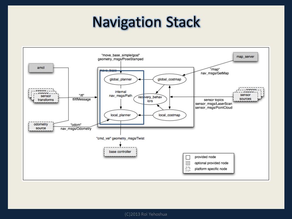
http://wiki.ros.org/navfn – A package that provides functions to create the plans The global plan is computed before the robot starts moving toward the next destination The planner assumes a circular robot and operates on a costmap to find a minimum cost plan from a start point to an end point in a grid. The navigation function is computed using Dijkstra's algorithm – support for an A* heuristic may also be added in the near future (C)2013 Roi Yehoshua
2013 Roi Yehoshua.")
5
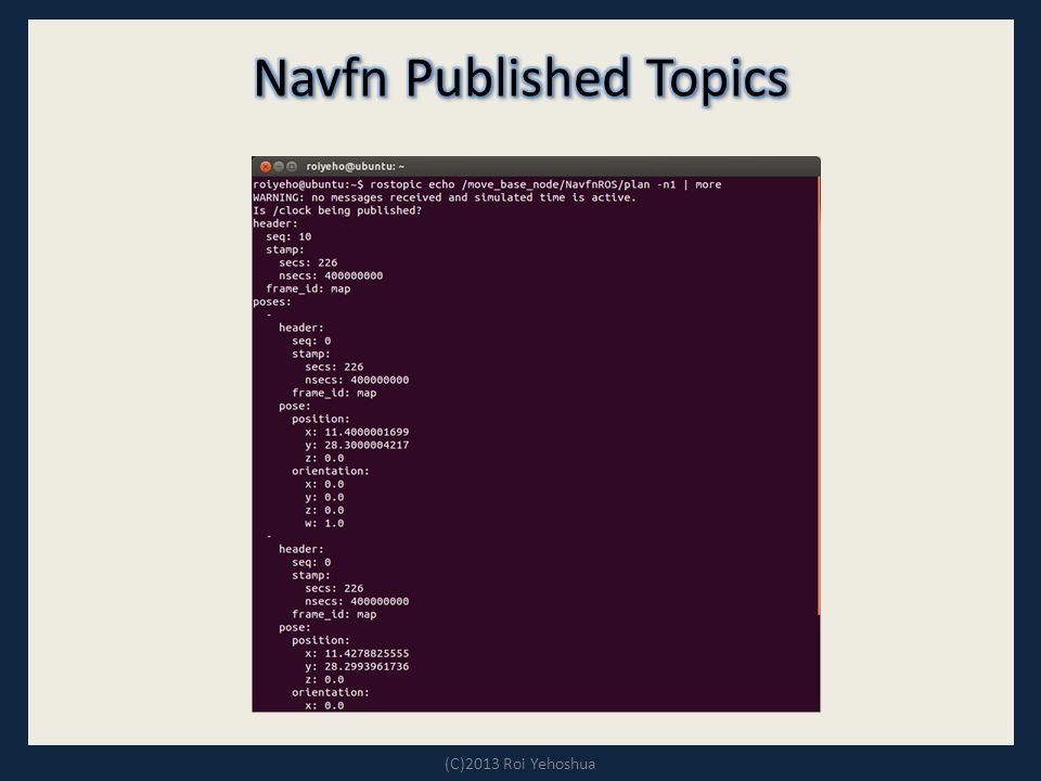
The last plan computed by navfn is published on the topic /move_base_node/NavfnROS/plan everytime the planner computes a new path – This is used primarily for visualization purposes Message type is nav_msgs/Pathnav_msgs/Path (C)2013 Roi Yehoshua
2013 Roi Yehoshua")
7
The navfn::NavfnROS object is a wrapper for a navfn::NavFn object that exposes its functionality as a C++ ROS Wrapper. It adheres to the nav_core::BaseGlobalPlanner interface found in the nav_core package.

8
http://wiki.ros.org/base_local_planner The local planner monitors incoming sensor data and chooses appropriate linear and angular velocities for the robot to traverse the current segment of the global path. The base_local_planner combines odometry data with both global and local cost maps to select a path for the robot to follow The base local planner can recompute the robot's path on the fly to keep the robot from striking objects yet still allowing it to reach its destination. (C)2013 Roi Yehoshua
2013 Roi Yehoshua.")
9
The base local planner implements the Trajectory Rollout and Dynamic Window algorithm References: – Brian P. Gerkey and Kurt Konolige. "Planning and Control in Unstructured Terrain". Discussion of the Trajectory Rollout algorithm in use on the LAGR robot. Brian P. Gerkey and Kurt Konolige. "Planning and Control in Unstructured Terrain" – D. Fox, W. Burgard, and S. Thrun. "The dynamic window approach to collision avoidance". The Dynamic Window Approach to local control. D. Fox, W. Burgard, and S. Thrun. "The dynamic window approach to collision avoidance". (C)2013 Roi Yehoshua
2013 Roi Yehoshua.")
10
1.Discretely sample in the robot's control space (dx,dy,dθ) 2.For each sampled velocity, perform forward simulation from the robot's current state to predict what would happen if the sampled velocity were applied for some (short) period of time. 3.Evaluate each trajectory resulting from the forward simulation, using a metric that incorporates characteristics such as: proximity to obstacles, proximity to the goal, proximity to the global path, and speed. 4.Discard illegal trajectories (those that collide with obstacles). 5.Pick the highest-scoring trajectory and send the associated velocity to the mobile base. 6.Rinse and repeat. (C)2013 Roi Yehoshua
. 5.Pick the highest-scoring trajectory and send the associated velocity to the mobile base. 6.Rinse and repeat. (C)2013 Roi Yehoshua.")
11
Taken from ROS Wiki

12
DWA (Dynamic Window Algorithm) differs from Trajectory Rollout in how the robot's control space is sampled. Trajectory Rollout samples from the set of achievable velocities over the entire forward simulation period given the acceleration limits of the robot, while DWA samples from the set of achievable velocities for just one simulation step given the acceleration limits of the robot. DWA is a more efficient algorithm because it samples a smaller space, but may be outperformed by Trajectory Rollout for robots with low acceleration limits because DWA does not forward simulate constant accelerations. In practice, DWA and Trajectory Rollout perform comparably and thus it is recommend to use of DWA for its efficiency gains. (C)2013 Roi Yehoshua
2013 Roi Yehoshua.")
13
In order to score trajectories efficiently, a Map Grid is used. For each control cycle, a grid is created around the robot (the size of the local costmap), and the global path is mapped onto this area. This means certain of the grid cells will be marked with distance 0 to a path point, and distance 0 to the goal. A propagation algorithm then efficiently marks all other cells with their Manhattan distance to the closest of the points marked with zero. (C)2013 Roi Yehoshua
, and the global path is mapped onto this area. This means certain of the grid cells will be marked with distance 0 to a path point, and distance 0 to the goal. A propagation algorithm then efficiently marks all other cells with their Manhattan distance to the closest of the points marked with zero. (C)2013 Roi Yehoshua.")
14
Oscillation occur when in either of the x, y, or theta dimensions, positive and negative values are chosen consecutively. To prevent oscillations, when the robot moves in any direction, for the next cycles the opposite direction is marked invalid, until the robot has moved beyond a certain distance from the position where the flag was set. (C)2013 Roi Yehoshua
2013 Roi Yehoshua.")
15
global_plan – The portion of the global plan that the local planner is currently attempting to follow – Message Type: nav_msgs/Pathnav_msgs/Path local_plan – The local plan or trajectory that scored the highest on the last cycle – Message Type: nav_msgs/Pathnav_msgs/Path cost_cloud – The cost grid used for planning – Message Type: sensor_msgs/PointCloud2sensor_msgs/PointCloud2 (C)2013 Roi Yehoshua
2013 Roi Yehoshua")
16
There are a large number of ROS Parameters that can be set to customize the behavior of the base_local_planner::TrajectoryPlannerROS wrapper. These parameters are grouped into several categories: – robot configuration – goal tolerance – forward simulation – trajectory scoring – oscillation prevention – global plan (C)2013 Roi Yehoshua
2013 Roi Yehoshua.")
17
DefaultDescriptionParameter 2.5The x acceleration limit of the robot in meters/sec^2acc_lim_x 2.5The y acceleration limit of the robot in meters/sec^2acc_lim_y 3.2The rotational acceleration limit of the robot in radians/sec^2 acc_lim_th 0.5The maximum forward velocity allowed for the base in meters/sec max_vel_x 0.1The minimum forward velocity allowed for the base in meters/sec. It is useful to specify this to guarantee that velocity commands sent to a mobile base are high enough to allow the base to overcome friction. min_vel_x 1.0The maximum rotational velocity allowed for the base in radians/sec max_rotational_vel 0.4The minimum rotational velocity allowed for the base while performing in-place rotations in radians/sec min_in_place_rotati onal_vel

18
(C)2013 Roi Yehoshua DefaultDescriptionParameter trueDetermines whether velocity commands are generated for a holonomic or non-holonomic robot. For holonomic robots, strafing velocity commands may be issued to the base. For non-holonomic robots, no strafing velocity commands will be issued. holonomic_robot [-0.3, -0.1, 0.1, 0.3] The strafing velocities that a holonomic robot will consider in meters/sec y_vels

19
(C)2013 Roi Yehoshua DefaultDescriptionParameter 0.05The tolerance in radians for the controller in yaw/rotation when achieving its goal yaw_goal_tolerance 0.10The tolerance in meters for the controller in the x & y distance when achieving a goal xy_goal_tolerance
2013 Roi Yehoshua DefaultDescriptionParameter 0.05The tolerance in radians for the controller in yaw/rotation when achieving its goal yaw_goal_tolerance 0.10The tolerance in meters for the controller in the x & y distance when achieving a goal xy_goal_tolerance")
20
(C)2013 Roi Yehoshua DefaultDescriptionParameter 1.0The amount of time to forward-simulate trajectories in seconds sim_time 0.025The step size, in meters, to take between points on a given trajectory sim_granularity 3The number of samples to use when exploring the x velocity space vx_samples 20The number of samples to use when exploring the theta velocity space vtheta_samples 20.0The frequency at which this controller will be called in Hz.controller_freque ncy
2013 Roi Yehoshua DefaultDescriptionParameter 1.0The amount of time to forward-simulate trajectories in seconds sim_time 0.025The step size, in meters, to take between points on a given trajectory sim_granularity 3The number of samples to use when exploring the x velocity space vx_samples 20The number of samples to use when exploring the theta velocity space vtheta_samples 20.0The frequency at which this controller will be called in Hz.controller_freque ncy")
21
The cost function used to score each trajectory is in the following form: (C)2013 Roi Yehoshua
2013 Roi Yehoshua")
22
DefaultDescriptionParameter 0.6The weighting for how much the controller should stay close to the path it was given pdist_scale 0.8The weighting for how much the controller should attempt to reach its local goal, also controls speed gdist_scale 0.01The weighting for how much the controller should attempt to avoid obstacles occdist_scale trueWhether to use the Dynamic Window Approach (DWA) or whether to use Trajectory Rollout (NOTE: In our experience DWA worked as well as Trajectory Rollout and is computationally less expensive. It is possible that robots with extremely poor acceleration limits could gain from running Trajectory Rollout, but we recommend trying DWA first.) dwa
 dwa.")
23
(C)2013 Roi Yehoshua #For full documentation of the parameters in this file, and a list of all the #parameters available for TrajectoryPlannerROS, please see #http://www.ros.org/wiki/base_local_planner TrajectoryPlannerROS: #Set the acceleration limits of the robot acc_lim_th: 3.2 acc_lim_x: 2.5 acc_lim_y: 2.5 #Set the velocity limits of the robot max_vel_x: 0.65 min_vel_x: 0.1 max_rotational_vel: 1.0 min_in_place_rotational_vel: 0.4 #The velocity the robot will command when trying to escape from a stuck situation escape_vel: -0.1 #For this example, we'll use a holonomic robot holonomic_robot: true #Since we're using a holonomic robot, we'll set the set of y velocities it will sample y_vels: [-0.3, -0.1, 0.1, -0.3] #For full documentation of the parameters in this file, and a list of all the #parameters available for TrajectoryPlannerROS, please see #http://www.ros.org/wiki/base_local_planner TrajectoryPlannerROS: #Set the acceleration limits of the robot acc_lim_th: 3.2 acc_lim_x: 2.5 acc_lim_y: 2.5 #Set the velocity limits of the robot max_vel_x: 0.65 min_vel_x: 0.1 max_rotational_vel: 1.0 min_in_place_rotational_vel: 0.4 #The velocity the robot will command when trying to escape from a stuck situation escape_vel: -0.1 #For this example, we'll use a holonomic robot holonomic_robot: true #Since we're using a holonomic robot, we'll set the set of y velocities it will sample y_vels: [-0.3, -0.1, 0.1, -0.3]
![(C)2013 Roi Yehoshua #For full documentation of the parameters in this file, and a list of all the #parameters available for TrajectoryPlannerROS, please see # TrajectoryPlannerROS: #Set the acceleration limits of the robot acc_lim_th: 3.2 acc_lim_x: 2.5 acc_lim_y: 2.5 #Set the velocity limits of the robot max_vel_x: 0.65 min_vel_x: 0.1 max_rotational_vel: 1.0 min_in_place_rotational_vel: 0.4 #The velocity the robot will command when trying to escape from a stuck situation escape_vel: -0.1 #For this example, we ll use a holonomic robot holonomic_robot: true #Since we re using a holonomic robot, we ll set the set of y velocities it will sample y_vels: [-0.3, -0.1, 0.1, -0.3] #For full documentation of the parameters in this file, and a list of all the #parameters available for TrajectoryPlannerROS, please see # TrajectoryPlannerROS: #Set the acceleration limits of the robot acc_lim_th: 3.2 acc_lim_x: 2.5 acc_lim_y: 2.5 #Set the velocity limits of the robot max_vel_x: 0.65 min_vel_x: 0.1 max_rotational_vel: 1.0 min_in_place_rotational_vel: 0.4 #The velocity the robot will command when trying to escape from a stuck situation escape_vel: -0.1 #For this example, we ll use a holonomic robot holonomic_robot: true #Since we re using a holonomic robot, we ll set the set of y velocities it will sample y_vels: [-0.3, -0.1, 0.1, -0.3]](http://images.slideplayer.com/15/4710691/slides/slide_23.jpg "(C)2013 Roi Yehoshua #For full documentation of the parameters in this file, and a list of all the #parameters available for TrajectoryPlannerROS, please see # TrajectoryPlannerROS: #Set the acceleration limits of the robot acc_lim_th: 3.2 acc_lim_x: 2.5 acc_lim_y: 2.5 #Set the velocity limits of the robot max_vel_x: 0.65 min_vel_x: 0.1 max_rotational_vel: 1.0 min_in_place_rotational_vel: 0.4 #The velocity the robot will command when trying to escape from a stuck situation escape_vel: -0.1 #For this example, we ll use a holonomic robot holonomic_robot: true #Since we re using a holonomic robot, we ll set the set of y velocities it will sample y_vels: [-0.3, -0.1, 0.1, -0.3] #For full documentation of the parameters in this file, and a list of all the #parameters available for TrajectoryPlannerROS, please see # TrajectoryPlannerROS: #Set the acceleration limits of the robot acc_lim_th: 3.2 acc_lim_x: 2.5 acc_lim_y: 2.5 #Set the velocity limits of the robot max_vel_x: 0.65 min_vel_x: 0.1 max_rotational_vel: 1.0 min_in_place_rotational_vel: 0.4 #The velocity the robot will command when trying to escape from a stuck situation escape_vel: -0.1 #For this example, we ll use a holonomic robot holonomic_robot: true #Since we re using a holonomic robot, we ll set the set of y velocities it will sample y_vels: [-0.3, -0.1, 0.1, -0.3]")
24
(C)2013 Roi Yehoshua #Set the tolerance on achieving a goal xy_goal_tolerance: 0.1 yaw_goal_tolerance: 0.05 #We'll configure how long and with what granularity we'll forward simulate trajectories sim_time: 1.7 sim_granularity: 0.025 vx_samples: 3 vtheta_samples: 20 #Parameters for scoring trajectories goal_distance_bias: 0.8 path_distance_bias: 0.6 occdist_scale: 0.01 heading_lookahead: 0.325 #We'll use the Dynamic Window Approach to control instead of Trajectory Rollout for this example dwa: true #How far the robot must travel before oscillation flags are reset oscillation_reset_dist: 0.05 #Eat up the plan as the robot moves along it prune_plan: true #Set the tolerance on achieving a goal xy_goal_tolerance: 0.1 yaw_goal_tolerance: 0.05 #We'll configure how long and with what granularity we'll forward simulate trajectories sim_time: 1.7 sim_granularity: 0.025 vx_samples: 3 vtheta_samples: 20 #Parameters for scoring trajectories goal_distance_bias: 0.8 path_distance_bias: 0.6 occdist_scale: 0.01 heading_lookahead: 0.325 #We'll use the Dynamic Window Approach to control instead of Trajectory Rollout for this example dwa: true #How far the robot must travel before oscillation flags are reset oscillation_reset_dist: 0.05 #Eat up the plan as the robot moves along it prune_plan: true
2013 Roi Yehoshua #Set the tolerance on achieving a goal xy_goal_tolerance: 0.1 yaw_goal_tolerance: 0.05 #We ll configure how long and with what granularity we ll forward simulate trajectories sim_time: 1.7 sim_granularity: vx_samples: 3 vtheta_samples: 20 #Parameters for scoring trajectories goal_distance_bias: 0.8 path_distance_bias: 0.6 occdist_scale: 0.01 heading_lookahead: #We ll use the Dynamic Window Approach to control instead of Trajectory Rollout for this example dwa: true #How far the robot must travel before oscillation flags are reset oscillation_reset_dist: 0.05 #Eat up the plan as the robot moves along it prune_plan: true #Set the tolerance on achieving a goal xy_goal_tolerance: 0.1 yaw_goal_tolerance: 0.05 #We ll configure how long and with what granularity we ll forward simulate trajectories sim_time: 1.7 sim_granularity: vx_samples: 3 vtheta_samples: 20 #Parameters for scoring trajectories goal_distance_bias: 0.8 path_distance_bias: 0.6 occdist_scale: 0.01 heading_lookahead: #We ll use the Dynamic Window Approach to control instead of Trajectory Rollout for this example dwa: true #How far the robot must travel before oscillation flags are reset oscillation_reset_dist: 0.05 #Eat up the plan as the robot moves along it prune_plan: true")
25
(C)2013 Roi Yehoshua The base_local_planner::TrajectoryPlannerROS object is a wrapper for a base_local_planner::TrajectoryPlanner object that exposes its functionality as a ROS Wrapper. It adheres to the nav_core::BaseLocalPlanner interface found in the nav_core package.

26
(C)2013 Roi Yehoshua
2013 Roi Yehoshua")
27
NavFn Plan – Displays the full plan for the robot computed by the global planner – Topic: /move_base_node/NavfnROS/plan Global Plan – It shows the portion of the global plan that the local planner is currently pursuing. – Topic: /move_base_node/TrajectoryPlannerROS/global_plan Local Plan – It shows the trajectory associated with the velocity commands currently being commanded to the base by the local planner – Topic: /move_base_node/TrajectoryPlannerROS/local_plan (C)2013 Roi Yehoshua
2013 Roi Yehoshua.")
28
NavFn Plan Global Plan Local Plan

29
(C)2013 Roi Yehoshua Run the rqt_reconfigure tool – This tool allows changing dynamic configuration values Open the move_base group Select the TrajectoryPlannerROS node Then set the pdist_scale parameter to something high like 2.5 After that, you should see that the local path (blue) now more closely follows the global path (yellow). $ rosrun rqt_reconfigure rqt_reconfigure

30
(C)2013 Roi Yehoshua
2013 Roi Yehoshua")
31
Local plan follows global plan

32
(C)2013 Roi Yehoshua
2013 Roi Yehoshua")
33
Localization is the problem of estimating the pose of the robot relative to a map Localization is not terribly sensitive to the exact placement of objects so it can handle small changes to the locations of objects ROS uses the amcl package for localization (C)2013 Roi Yehoshua
2013 Roi Yehoshua")
34
amcl is a probabilistic localization system for a robot moving in 2D. It implements the adaptive Monte Carlo localization approach, which uses a particle filter to track the pose of a robot against a known map. The algorithm and its parameters are described in the book Probabilistic Robotics by Thrun, Burgard, and Fox. – http://www.probabilistic-robotics.org/ http://www.probabilistic-robotics.org/ As currently implemented, this node works only with laser scans and laser maps. It could be extended to work with other sensor data. (C)2013 Roi Yehoshua
2013 Roi Yehoshua.")
35
amcl takes in a laser-based map, laser scans, and transform messages, and outputs pose estimates Subscribed topics: – scan – Laser scans – tf – Transforms – initialpose – Mean and covariance with which to (re-) initialize the particle filter – map – the map used for laser-based localization Published topics: – amcl_pose – Robot's estimated pose in the map, with covariance. – Particlecloud – The set of pose estimates being maintained by the filter (C)2013 Roi Yehoshua
2013 Roi Yehoshua.")
36
DefaultDescriptionParameter 100Minimum allowed number of particlesmin_particles 5000Maximum allowed number of particlesmax_particles likelihood_fieldWhich model to use, either beam or likelihood_fieldlaser_model_type 2.0Maximum distance to do obstacle inflation on map, for use in likelihood_field model laser_likelihood_ max_dist 0.0Initial pose mean (x), used to initialize filter with Gaussian distribution initial_pose_x 0.0Initial pose mean (y), used to initialize filter with Gaussian distribution initial_pose_y 0.0Initial pose mean (yaw), used to initialize filter with Gaussian distribution initial_pose_a
, used to initialize filter with Gaussian distribution initial_pose_x 0.0Initial pose mean (y), used to initialize filter with Gaussian distribution initial_pose_y 0.0Initial pose mean (yaw), used to initialize filter with Gaussian distribution initial_pose_a")
37
(C)2013 Roi Yehoshua <!-- Example amcl configuration. Descriptions of parameters, as well as a full list of all amcl parameters, can be found at http://www.ros.org/wiki/amcl. --> <!-- Example amcl configuration. Descriptions of parameters, as well as a full list of all amcl parameters, can be found at http://www.ros.org/wiki/amcl. -->

38
(C)2013 Roi Yehoshua --> -->
2013 Roi Yehoshua --> -->")
39
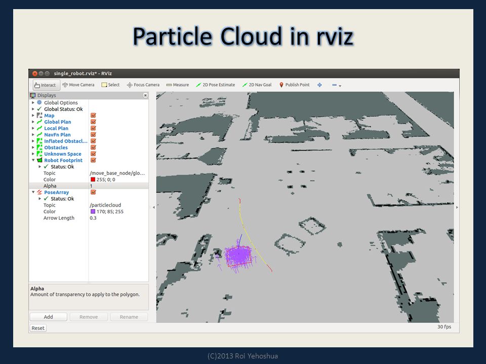
The Particle Cloud displays shows the particle cloud used by the robot's localization system. The spread of the cloud represents the localization system's uncertainty about the robot's pose. – A cloud that spreads out a lot reflects high uncertainty, while a condensed cloud represents low uncertainty As the robot moves about the environment, this cloud should shrink in size as additional scan data allows amcl to refine its estimate of the robot's position and orientation (C)2013 Roi Yehoshua
2013 Roi Yehoshua.")
40
To watch the particle cloud in rviz: – Click Add Display and choose Pose Array – Set topic name to /particlecloud (C)2013 Roi Yehoshua
2013 Roi Yehoshua")
42
Taken from ROS by Example / Goebel

43
http://wiki.ros.org/fake_localization A ROS node that simply forwards odometry information. Substitutes for a localization system – Converts odometry data into pose, particle cloud, and transform data of the form published by amcl. Mostly used during simulation as a method to provide perfect localization in a computationally inexpensive manner. (C)2013 Roi Yehoshua
2013 Roi Yehoshua.")
Similar presentations


 be a point. We want to estimate an elevation at a point q: 1. should.>")


 Jerome Barraquand Jean-Claude Latombe.>")


