Download presentation
Presentation is loading. Please wait.

1
4.9 Stability at Large Angles of Inclination
The transverse metacenter height is a measure of the stability under ‘initial stability’ (aka small angle stability). When the angle of inclination exceeds 5 degrees, the metacenter can be no longer regarded as a fixed point relative to the ship. Hence, the transverse metacenter height (GM) is no longer a suitable criterion for measuring the stability of the ship and it is usual to use the value of the righting arm GZ for this purpose.
. When the angle of inclination exceeds 5 degrees, the metacenter can be no longer regarded as a fixed point relative to the ship. Hence, the transverse metacenter height (GM) is no longer a suitable criterion for measuring the stability of the ship and it is usual to use the value of the righting arm GZ for this purpose.")
2
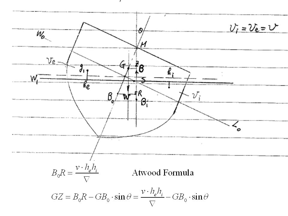
The Derivation of Atwood’s Formula
: W.L. when the ship is at upright position. : W.L. when the ship is inclined at an angle θ. If the ship section is not vertically sided, the two W.L., underneath which there must be the same volume, do not intersect on the center line (as in the initial stability) but at S.
 but at S.")
4
GZ vs. For each angle of θ, we compute GZ, the righting arm.
The ship is unstable beyond B. (even if the upsetting moment is removed, the ship will not return to its upright position). From 0 to B, the range of angles represents the range of stabilities.
. From 0 to B, the range of angles represents the range of stabilities.")
5
Ex. Righting arm of a ship vertically sided (A special example to compute GZ at large angle inclinations) Transverse moment of volume shifted = Volume arm Transverse shift of C.B.

6
Ex. Righting arm of a ship vertically sided (A special example to compute GZ at large angle inclinations) Similarly, vertical moment of volume shifted = Volume Arm Vertical shift of C.B.

7
Ex. Righting arm of a ship vertically sided (A special example to compute GZ at large angle inclinations)
.")
8
Cross Curves of Stability
It is difficult to ascertain the exact W.L. at which a ship would float in the large angle inclined condition for the same displacement as in the upright condition. The difficulty can be avoided by obtaining the cross curves of stability (see p44). How to Computing them Assume the position of C.G. (not known exactly) W.L. I - V should cover the range of various displacements which a ship may have.
. How to Computing them. Assume the position of C.G. (not known exactly) W.L. I - V should cover the range of various displacements which a ship may have.")
9
Cross Curves of Stability
Computation Procedures The transverse section area under waterline I, II, III, IV, V The moment about the vertical y-axis (passing through C.G) By longitudinal integration along the length, we obtain the displacement volume, the distances from the B.C. to y-axis (i.e. the righting arm GZ) under the every W.L. For every we obtain Plot the cross curves of stability.
 By longitudinal integration along the length, we obtain the displacement volume, the distances from the B.C. to y-axis (i.e. the righting arm GZ) under the every W.L. For every we obtain. Plot the cross curves of stability.")
10
Cross Curves of Stability
These curves show that the righting arm (GZ) changes with the change of displacement given the inclination angle of the ship.
 changes with the change of displacement given the inclination angle of the ship.")
11
For the sake of understanding ‘cross curves of stability’ clearly, here is a 3-D plot of ‘cross curves of stability.’ The curved surface is

12
Curve of Static Stability
‘Curve of static stability’ is a curve of righting arm GZ as a function of angle of inclination for a fixed displacement. Computing it based on cross curves of stability. How to determine a curve of statical stability from a 3-D of ‘cross curves of stability.’ (C.C.S.), e.g., the curve of static stability is the intersection of the curved surface and the plane of a given displacement. Determining a C.S.S. from 2-D ‘C.C.S.’ is to let displcement = const., which intersects those cross curves at point A, B,…, see the figure.
, e.g., the curve of static stability is the intersection of the curved surface and the plane of a given displacement. Determining a C.S.S. from 2-D ‘C.C.S.’ is to let displcement = const., which intersects those cross curves at point A, B,…, see the figure.")
13
GZ

14
Influences of movement of G.C on ‘curve of static stability’
Vertical movement (usually due to the correction of G.C position after inclining experiment.)
")
15
Influences of movement of G.C on ‘curve of static stability’
2. Transverse movement (due to the transverse movement of some loose weight) Weight moving from the left to the right
 Weight moving from the left to the right.")
16
Features of A Curve of Static Stability
Rises steadily from the origin and for the first few degrees is practically a straight line. Near the origin GZ = θ * slope & slope = ?, why? 2. Usually have a point of inflexion, concave upwards and concave downwards, then reaches maximum, and afterwards, declines and eventually crosses the base (horizontal axis). 1 radian
. 1 radian.")
17
The maximum righting arm & the range of stability are to a large extent a function of the freeboard.
(the definition of freeboard) Larger freeboard Larger GZmax & the range of stability Using the watertight superstructures Larger GZmax & the range of stability
 Larger freeboard Larger GZmax & the range of stability. Using the watertight superstructures Larger GZmax & the range of stability.")
18
4.10 Dynamic Stability Static stability: we only compute the righting arm (or moment) given the angle of inclination. A true measure of stability should considered dynamically. Dynamic Stability: Calculating the amount of work done by the righting moment given the inclination of the ship.
 given the angle of inclination. A true measure of stability should considered dynamically. Dynamic Stability: Calculating the amount of work done by the righting moment given the inclination of the ship.")
19
Influence of Wind on Stability (p70-72)
Upsetting moment due to beam wind

20
When the ship is in upright position, the steady beam wind starts to blow and the ship begins to incline. At point A, the M(wind) = M(righting), do you think the ship will stop inclining at A? Why? The inclination will usually not stop at A. Because the rolling velocity of a ship is not equal to zero at A, the ship will continue to incline. To understand this, let’s review a simple mechanical problem

21
the work done by the spring force R,
The external force F = constant The work done by it If at the work done by the spring force R, F m R No Friction X = 0 X X = X1 Hence, the block will continue to move to the right. It will not stop until

22
In a ship-rolling case:
Work done by the upright moment Work done by the wind force It will stop rolling (at E) In a static stability curve or simply,
 In a static stability curve. or simply,")
23
Consideration in Design (The most sever case concerning the ship stability)
Suppose that the ship is inclining at angle and begins to roll back to its upright position. Meanwhile, the steady beam wind is flowing in the same direction as the ship is going to roll. θ0 Wind

24
Standards of Stability: ships can withstand
winds up to 100 knots; rolling caused by sever waves; heel generated in a high speed turn; lifting weights over one side (the C.G. of the weight is acting at the point of suspension); the crowding of passengers to one side.
; the crowding of passengers to one side.")
25
4.11 Flooding & Damaged Stability
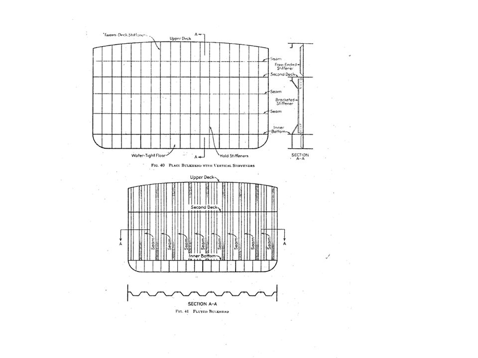
So far we consider the stability of an intact ship. In the event of collision or grounding, water may enter the ship. If flooding is not restricted, the ship will eventually sink. To prevent this, the hull is divided into a number of watertight compartments by watertight bulkheads. (see the figure) Transverse (or longitudinal) watertight bulkheads can Minimize the loss of buoyancy Minimize the damage to the cargo Minimize the loss of stability
 Transverse (or longitudinal) watertight bulkheads can. Minimize the loss of buoyancy. Minimize the damage to the cargo. Minimize the loss of stability.")
27
Too many watertight bulkheads will increase cost & weight of the ship
Too many watertight bulkheads will increase cost & weight of the ship. It is attempted to use the fewest watertight bulkheads to obtain the largest possible safety (or to satisfy the requirement of rule). Forward peak bulkhead (0.05 L from the bow) After peak bulkhead Engine room: double bottom Tanker: (US Coast Guard) Double Hull (anti pollution) This section studies the effects of flooding on the hydrostatic properties and stability
. Forward peak bulkhead (0.05 L from the bow) After peak bulkhead. Engine room: double bottom. Tanker: (US Coast Guard) Double Hull (anti pollution) This section studies the effects of flooding on the. hydrostatic properties. and stability.")
28
Trim when a compartment is open to Sea
If W1L1 is higher at any point than the main deck at which the bulkheads stop (the bulkhead deck) it is usually considered that the ship will be lost (sink) because the pressure of water in the damaged compartments can force off the hatches and unrestricted flooding will occur all fore and aft.
 it is usually considered that the ship will be lost (sink) because the pressure of water in the damaged compartments can force off the hatches and unrestricted flooding will occur all fore and aft.")
29
(1) Lost buoyancy method
 Lost buoyancy method")
32
Ex. p A vessel of constant rectangular cross-section L = 60 m, B = 10 m, T = 3 m. ZG = 2.5 m l0 = 8 m. L1 L0 l0 = 8 m w1 w0 2) Parallel sinkage
 Parallel sinkage.")
33
3) Draft at midway between W0L0 – W1L1 :
 Draft at midway between W0L0 – W1L1 :")
34
Moment for Trim per meter:

36
if Find trim. MTI ( at )
")
37
(2) Added Weight Method (considering the loss of buoyancy as added weight)
also a Trial – error (iterative) method 1) Find added weight v under W0L0. Total weight = W + v 2.) According to hydrostatic curve , determine W1L1 (or T) & trim (moment caused by the added weight & MTI). 3.) Since we have a larger T, and v will be larger, go back to step 1) re-compute v. The iterative computation continues until the difference between two added weights v obtained from the two consecutive computation is smaller than a prescribed error tolerance.
 method. 1) Find added weight v under W0L0. Total weight = W + v. 2.) According to hydrostatic curve , determine W1L1 (or T) & trim (moment caused by the added weight & MTI). 3.) Since we have a larger T, and v will be larger, go back to step 1) re-compute v. The iterative computation continues until the difference. between two added weights v obtained from the two. consecutive computation is smaller than a prescribed error. tolerance.")
38
Stability in damaged condition

39
Asymmetric flooding If the inclination angle is large, then the captain should let the corresponding tank flooding. Then the flooding is symmetric. If the inclination angle is small,

40
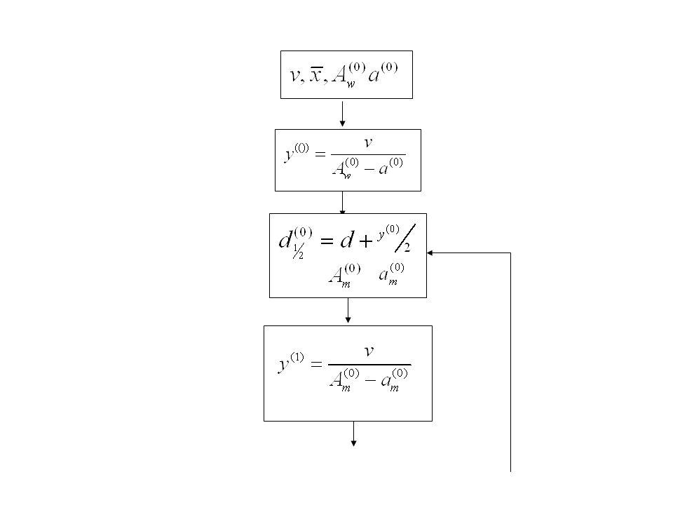
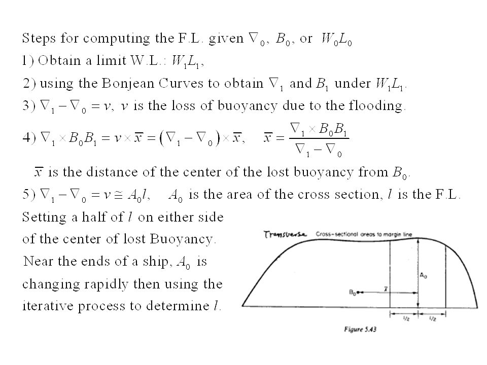
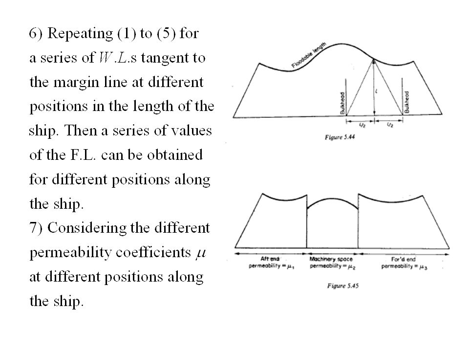
Floodable length and its computation
Floodable Length: The F.L. at any point within the length of the ship is the maximum portion of the length, having its center at the point which can be symmetrically flooded at the prescribed permeability, without immersing the margin line.

41
Without loss of the ship: When the W.L. is tangent to the margin line.
Bulkhead deck: The deck tops the watertight bulkhead Margin line: is a line 75 mm (or 3”) below the bulkhead at the side of a ship Without loss of the ship: When the W.L. is tangent to the margin line. Floodable length (in short) The length of (part of) the ship could be flooded without loss of the ship. Determine Floodable length is essential to determine How many watertight compartments (bulkheads) needed Factor of subdivision (How many water compartments flooded without lost ship)
 below the bulkhead at the side of a ship. Without loss of the ship: When the W.L. is tangent to the margin line. Floodable length (in short) The length of (part of) the ship could be flooded without loss of the ship. Determine Floodable length is essential to determine. How many watertight compartments (bulkheads) needed. Factor of subdivision (How many water compartments flooded without lost ship)")
44
8) Factor of Subdivision F
Factor of subdivision is the ratio of a permissible length to the F.L. For example, if F is 0.5, the ship will still float at a W.L. under the margin line when any two adjacent compartments of the ship are flooded. If F is 1.0, the ship will still float at a W.L. under the margin line when any one compartment of the ship is flooded. Rules and regulations about the determination of F are set by many different bureaus all over the world (p )
")
Similar presentations


 Floatation & Stability>")


INE: Ch 22 (389-400) INE: Ch 23 (401-402, 409)INE: Ch 23 (401-402, 409) PNE: Ch 3 (1-10)PNE: Ch.>")


