Download presentation
Presentation is loading. Please wait.

1
Radar Mapping

2
Electromagnetic EM Radiation Electric Field & Magnetic Field –Perpendicular to direction of propagation Explains light but is absolutely fundamental for radio spectrum

3
Typical Radar System 1.A pulse generator that discharges timed pulses of microwave/radio energy 2.A transmitter 3.A duplexer that alternates the signals involved between transmitted and received 4.A directional antenna that shapes and focuses each pulse into a stream 5.Receiving Antenna

4
Radar Bands 1.Ka Band: Frequency 40,000-26,000 MHz; Wavelength (0.8-1.1 cm) 2.K Band: 26,500-18,500 MHz; (1.1-1.7 cm) = Weather Radar 3.X Band: 12,500-8,000 MHz; (2.4-3.8 cm) 4.C Band: 8,000-4,000 MHz; (3.8-7.5 cm) 5.L Band: 2,000-1,000 MHz; (15.0-30.0 cm) 6.P Band: 1,000- 300 MHz; (30.0-100.0 cm) These are all in the Microwave part of the spectrum
 2.K Band: 26,500-18,500 MHz; ( cm) = Weather Radar 3.X Band: 12,500-8,000 MHz; ( cm) 4.C Band: 8,000-4,000 MHz; ( cm) 5.L Band: 2,000-1,000 MHz; ( cm) 6.P Band: 1, MHz; ( cm) These are all in the Microwave part of the spectrum")
5
About Radar RADAR = RAdio Detection And Ranging Typically radar transmitters send and receive 1500 pulses per second Pulses last about.1 microsecond Pulses send 100-1000 waves What a radar actually measures is time (between transmission and reception) What a radar actually receives when it’s pointed in a certain direction isn’t always in that direction
 What a radar actually receives when it’s pointed in a certain direction isn’t always in that direction")
6
Some Radar Effects

7
Bright = rough, Dark = smooth Metal reflects brightly Metal corners or edges reflect especially brightly –A truck has same size radar signature as a bomber –Stealth = eliminate sharp edges and conductive materials Look direction = Illumination on Image

8
What Determines Radar Echo Electrical properties of material (Dielectric Constant) –Conductive = High Dielectric Constant = Reflective –Non-conductive = Low Dielectric Constant = Non-Reflective Roughness –Can’t “see” things smaller than wavelength –Corners are effective for scattering
 –Conductive = High Dielectric Constant = Reflective –Non-conductive = Low Dielectric Constant = Non-Reflective Roughness –Can’t see things smaller than wavelength –Corners are effective for scattering")
9
Some Dielectric Constants Air: 1 Teflon: 2 Glass: 5-10 Water: 80

10
Radar Image of ISS

11
Radar and Optical

12
Stereoscopic SLAR

13
Radar Stereoscopy Although radar images can be viewed to give a 3-dimensional appearance, true photogrammetry is far more complex than with optical imaging. It can be done, although when NASA began radar mapping of Venus they didn’t yet have the ability.

14
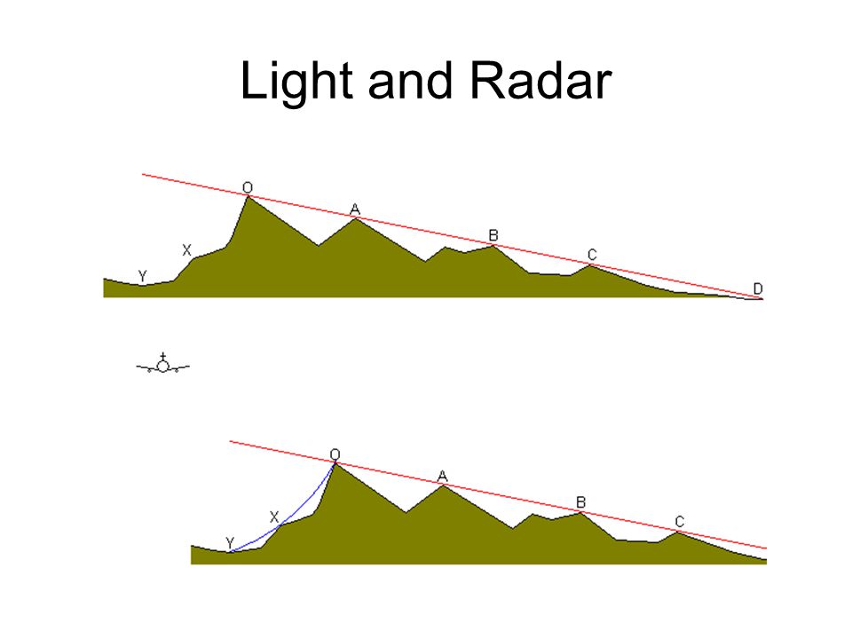
Light and Radar

16
Light Vs. Radar

17
How Time = Illusion

18
Radar Foreshortening With optical foreshortening, the facing side of a mountain looks normal and the back side looks compressed With radar foreshortening, the facing side of a mountain looks normal and the back side looks longer Layover: On steep slopes objects may appear to overlap because they’re the same distance (time) away.
 away.")
19
Light vs. Radar

21
Layover

22
Radar Foreshortening

23
Layover and Foreshortening

24
Underwater Radar?

25
Sonar View

26
How Time = Illusion

27
Sonar Views of Shipwrecks

28
German Bomber

29
Polarization Radar signals are polarized parallel to their transmitting antenna H (horizontal) polarization = parallel to bottom of plane When signals scatter, some of the polarization is lost What we see depends on the orientation of the receiving antenna
 polarization = parallel to bottom of plane When signals scatter, some of the polarization is lost What we see depends on the orientation of the receiving antenna")
30
Polarization Imagine a signal from a perfectly horizontal antenna It bounces off a perfectly flat surface perpendicular to the beam A receiver parallel to the transmitting antenna will get 100% return A receiver perpendicular to the transmitting antenna will get 0% return

31
HV vs. HH

32
Multiband Color Composite

33
Alaska Coast

34
Reflectivity and Penetration, Florida

35
Reflectivity, Southern California

36
IR + Radar

37
Radar Penetration of Sand, Sudan

38
Ground Penetrating Radar

39
Optical and Radar Imagery

40
TOPEX/Poseidon

41
The Sea Is Not Flat

42
Pacific Ocean Sea Surface Changes

43
Sea Surface Radar Mapping

44
2004 Tsunami

45
Global Wind Speed and Wave Heights

46
Radar Image of Hawaii

47
Lidar LIght Detection And Ranging Uses laser pulses to measure distance Anything that affects light affects Lidar –Blocked by clouds, smoke, aerosols –Can monitor clouds, smoke, aerosols Records distance and direction Depending on processing, can image vegetation canopy or ground

48
Lidar

49
Mount St. Helens

50
Neolithic Mound, Slovakia

51
Hopewell Mounds, Ohio

52
Hopewell Mounds Ground View

53
Caracol, Belize

56
Caracol, Belize, Point Cloud

57
Bainbridge Island, WA

58
Tacoma Fault and Glacial Troughs

Similar presentations


 developed during WW II –Sound pulses emitted reflected off metal objects with characteristic.>")


