Download presentation
Presentation is loading. Please wait.

1
Chapter 4 Energy Analysis of Closed Systems

2
Energy Transfer Energy can cross the boundary of a closed system in two distinct forms: heat and work (Fig. 4–1). Heat is defined as the form of energy that is transferred between two systems (or a system and its surroundings) by virtue of a temperature difference. If the energy crossing the boundary of a closed system is not heat, it must be work.
 by virtue of a temperature difference. If the energy crossing the boundary of. a closed system is not heat, it must be work.")
3
Sign Convention of Heat and Work
The generally accepted formal sign convention for heat and work interactions is as follows: heat transfer to a system and work done by a system are positive;heat transfer from a system and work done on a system are negative. A quantity that is transferred to or from a system during an interaction is not a property since the amount of such a quantity depends path and not the state of the system. Heat and work are energy transfer mechanisms between a system and its urroundings, and there are many similarities between them: Both are recognized at the boundaries of a system as they cross the boundaries. Systems possess energy, but not heat or work. Both are associated with a process, not a state. Unlike properties, heat or work has no meaning at a state. Both are path functions (i.e., their magnitudes depend on the path followed during a process as well as the end states).
.")
4
Mechanical Work Moving Boundary Work-
One form of mechanical work frequently encountered in practice is associated with the expansion or compression of a gas in a piston-cylinder device. During this process, part of the boundary (the inner face of the piston) moves back and forth. Therefore, the expansion and compression work is often called moving boundary work, or simply boundary work
 moves back and forth. Therefore, the expansion and compression work is often called moving boundary work, or simply boundary work.")
5
Since the work is process dependent, the differential of boundary work Wb
is called inexact. The above equation for Wb is valid for a quasi-equilibrium process and gives the maximum work done during expansion and the minimum work input during compression. In an expansion process the boundary work must overcome friction, push the atmospheric air out of the way, and rotate a crankshaft. To calculate the boundary work, the process by which the system changed states must be known. Once the process is determined, the pressure-volume relationship for the process can be obtained and the integral in the boundary work equation can be performed. For each process we need to determine:

6
So as we work problems, we will be asking, “What is the pressure-volume relationship for the process?” Remember that this relation is really the force-displacement function for the process. The boundary work is equal to the area under the process curve plotted on the pressure-volume diagram.

7
Note from the above figure:
P is the absolute pressure and is always positive. When dV is positive, Wb is positive. When dV is negative, Wb is negative. Since the areas under different process curves on a P-V diagram are different, the boundary work for each process will be different. The next figure shows that each process gives a different value for the boundary work.

8
Other Type of Mechanical Works
Elastic work Surface tension work Work Done to Raise or to Accelerate a Body

9
Some Typical Processes
Constant volume If the volume is held constant, dV = 0, and the boundary work equation becomes P-V diagram for V = constant P 1 2 V If the working fluid is an ideal gas, what will happen to the temperature of the gas during this constant volume process?

10
Constant pressure P V 2 1 P-V DIAGRAM for P = CONSTANT If the pressure is held constant, the boundary work equation becomes For the constant pressure process shown above, is the boundary work positive or negative and why?

11
Constant temperature, ideal gas
If the temperature of an ideal gas system is held constant, then the equation of state provides the pressure-volume relation Then, the boundary work is Note: The above equation is the result of applying the ideal gas assumption for the equation of state. For real gases undergoing an isothermal (constant temperature) process, the integral in the boundary work equation would be done numerically.
 process, the integral in the boundary work equation would be done numerically.")
12
The polytropic process
The polytropic process is one in which the pressure-volume relation is given as The exponent n may have any value from minus infinity to plus infinity depending on the process. Some of the more common values are given below. Process Exponent n Constant pressure 0 Constant volume Isothermal & ideal gas 1 Adiabatic & ideal gas k = CP/CV Here, k is the ratio of the specific heat at constant pressure CP to specific heat at constant volume CV. The specific heats will be discussed later.

13
The boundary work done during the polytropic process is found by substituting the pressure-volume relation into the boundary work equation. The result is For an ideal gas under going a polytropic process, the boundary work is Notice that the results we obtained for an ideal gas undergoing a polytropic process when n = 1 are identical to those for an ideal gas undergoing the isothermal process.

14
System: Nitrogen contained in a piston-cylinder device.
2 Example 4-2 Three kilograms of nitrogen gas at 27C and 0.15 MPa are compressed isothermally to 0.3 MPa in a piston-cylinder device. Determine the minimum work of compression, in kJ. System: Nitrogen contained in a piston-cylinder device. Process: Constant temperature P-V DIAGRAM for T = CONSTANT P V 1 Wb Nitrogen gas System Boundary

15
For an ideal gas in a closed system (mass = constant), we have
Work Calculation: For an ideal gas in a closed system (mass = constant), we have Since the R's cancel, we obtain the combined ideal gas equation. Since T2 = T1,
, we have. Since the R s cancel, we obtain the combined ideal gas equation. Since T2 = T1,")
16
The net work is On a per unit mass basis The net work is negative because work is done on the system during the compression process. Thus, the work done on the system is kJ, or kJ of work energy is required to compress the nitrogen.

17
Example 4-3 Water is placed in a piston-cylinder device at 20 C, 0.1 MPa. Weights are placed on the piston to maintain a constant force on the water as it is heated to 400 C. How much work does the water do on the piston? System: The water contained in the piston-cylinder device Heat System Boundary for water Wb Property Relation: Steam tables Process: Constant pressure

18
Work Calculation: Since there is no Wother mentioned in the problem, the net work is Since the mass of the water is unknown, we calculate the work per unit mass.

19
At T1 = 20C, Psat = 2. 339 kPa. Since P1 > 2
At T1 = 20C, Psat = kPa. Since P1 > kPa, state 1 is compressed liquid. Thus, v1 vf at 20 C = m3/ kg At P2 = P1 = 0.1 MPa, T2 > Tsat at 0.1 MPa = 99.61C. So, state 2 is superheated. Using the superheated tables at 0.1 MPa, 400C v2 = m3/kg The water does work on the piston in the amount of kJ/kg.

20
Example 4-4 One kilogram of water is contained in a piston-cylinder device at 100 C. The piston rests on lower stops such that the volume occupied by the water is m3. The cylinder is fitted with an upper set of stops. When the piston rests against the upper stops, the volume enclosed by the piston-cylinder device is m3. A pressure of 200 kPa is required to support the piston. Heat is added to the water until the water exists as a saturated vapor. How much work does the water do on the piston? System: The water contained in the piston-cylinder device P Stops System Boundary Stops v Wb Wb Water

21
Property Relation: Steam tables
Process: Combination of constant volume and constant pressure processes to be shown on the P-v diagram as the problem is solved. Work Calculation: The specific volume at state 1 is: At T1 = 100C, Therefore, vf < v1 < vg and state 1 is in the saturation region; so P1 = kPa. Show this state on the P-v diagram. Now let’s consider the processes for the water to reach the final state. Process 1-2: The volume stays constant until the pressure increases to 200 kPa. Then the piston will move.

22
Process 2-3: Piston lifts off the bottom stops while the pressure stays constant. Does the piston hit the upper stops before or after reaching the saturated vapor state? Let's set At P3 = P2 = 200 kPa Thus, vf < v3 < vg. So, the piston hits the upper stops before the water reaches the saturated vapor state. Now we have to consider a third process. Process 3-4: With the piston against the upper stops, the volume remains constant during the final heating to the saturated vapor state and the pressure increases. Because the volume is constant in process 3-to-4, v4 = v3 = m3/kg and v4 is a saturated vapor state. Interpolating in either the saturation pressure table or saturation temperature table at v4 = vg gives

23
The net work for the heating process is (the “other” work is zero)
Later in Chapter 4, we will apply the conservation of energy, or the first law of thermodynamics, to this process to determine the amount of heat transfer required. Example 4-5 Air undergoes a constant pressure cooling process in which the temperature decreases by 100C. What is the magnitude and direction of the work for this process?

24
System: Example 4-6 The work per unit mass is:
Air Wb System Boundary P V 2 1 The work per unit mass is: The work done on the air is 28.7 kJ/kg. Example 4-6 Find the required heat transfer to the water in Example 4-4. Review the solution procedure of Example 4-4 and then apply the first law to the process.

25
Closed System First Law
The first law of thermodynamics is an expression of the conservation of energy principle. Energy can cross the boundaries of a closed system in the form of heat or work. Energy transfer across a system boundary due solely to the temperature difference between a system and its surroundings is called heat. Closed System First Law A closed system moving relative to a reference plane is shown below where z is the elevation of the center of mass above the reference plane and is the velocity of the center of mass. Heat Work z Closed System Reference Plane, z = 0 For the closed system shown above, the conservation of energy principle or the first law of thermodynamics is expressed as:

26
or According to classical thermodynamics, we consider the energy added to be net heat transfer to the closed system and the energy leaving the closed system to be net work done by the closed system. So Where Normally the stored energy, or total energy, of a system is expressed as the sum of three separate energies. The total energy of the system, Esystem, is given as:

27
Recall that U is the sum of the energy contained within the molecules of the system other than the kinetic and potential energies of the system as a whole and is called the internal energy. The internal energy U is dependent on the state of the system and the mass of the system. For a system moving relative to a reference plane, the kinetic energy KE and the potential energy PE are given by: The change in stored energy for the system is: Now the conservation of energy principle, or the first law of thermodynamics for closed systems, is written as:

28
Closed System First Law for a Cycle
If the system does not move with a velocity and has no change in elevation, the conservation of energy equation reduces to: Closed System First Law for a Cycle Since a thermodynamic cycle is composed of processes that cause the working fluid to undergo a series of state changes through a series of processes such that the final and initial states are identical, the change in internal energy of the working fluid is zero for whole numbers of cycles. The first law for a closed system operating in a thermodynamic cycle becomes

29
Example 4-1 Complete the table given below for a closed system under going a cycle. Process Qnet kJ Wnet kJ U2 – U1 kJ Cycle

30
Conservation of Energy:
In Example 4-4 we found that The heat transfer is obtained from the first law as: where

31
At state 1, T1 = 100C, v1 = 0. 835 m3/kg and vf < v1 < vg at T1
At state 1, T1 = 100C, v1 = m3/kg and vf < v1 < vg at T1. The quality at state 1 is Because state 4 is a saturated vapor state and v4 = m3/kg, interpolating in either the saturation pressure table or saturation temperature table at v4 = vg gives So

32
The heat transfer is Heat in the amount of kJ is added to the water. Specific Heats and Changes in Internal Energy and Enthalpy for Ideal Gases Before the first law of thermodynamics can be applied to systems, ways to calculate the change in internal energy of the substance enclosed by the system boundary must be determined. For real substances like water, the property tables are used to find the internal energy change. For ideal gases the internal energy is found by knowing the specific heats. Physics defines the amount of energy needed to raise the temperature of a unit of mass of a substance one degree as the specific heat at constant volume CV for a constant-volume process, and the specific heat at constant pressure CP for a constant-pressure process. Recall that enthalpy h is the sum of the internal energy u and the pressure-volume product Pv. In thermodynamics, the specific heats are defined as :

33
Simple Substance The thermodynamic state of a simple, homogeneous substance is specified by giving any two independent, intensive properties. Let's consider the internal energy to be a function of T and v and the enthalpy to be a function of T and P as follows:

34
This result helps to show that the internal energy of an ideal gas does not depend upon specific volume. To completely show that internal energy of an ideal gas is independent of specific volume, we need to show that the specific heats of ideal gases are functions of temperature only. We will do this later in Chapter 12. A similar result that applies to the enthalpy function for ideal gases can be reviewed in Chapter 12. Then for ideal gases, The ideal gas specific heats are written in terms of ordinary differentials as

35
Using the simple “dumbbell model” for diatomic ideal gases, statistical thermodynamics predicts the molar specific heat at constant pressure as a function of temperature to look like the following “Dumbbell model” T Translation mode Vibration mode Rotation mode The following figure shows how the molar specific heats vary with temperature for selected ideal gases.

36
The differential changes in internal energy and enthalpy for ideal gases become
The change in internal energy and enthalpy of ideal gases can be expressed as

37
Process 1-2a: Constant volume
where CV,ave and CP,ave are average or constant values of the specific heats over the temperature range. We will drop the ave subscript shortly. 2a 2b T2 T1 2c 1 P-V diagram for several processes for an ideal gas. P V In the above figure an ideal gas undergoes three different process between the same two temperatures. Process 1-2a: Constant volume Process 1-2b: P = a + bV, a linear relationship Process 1-2c: Constant pressure These ideal gas processes have the same change in internal energy and enthalpy because the processes occur between the same temperature limits.

38
To find u and h we often use average, or constant, values of the specific heats. Some ways to determine these values are as follows: 1.The best average value (the one that gives the exact results) See Table A-2(c) for variable specific data. 2.Good average values are and
 See Table A-2(c) for variable specific data. 2.Good average values are. and.")
39
A similar result is found for the change in internal energy.
These last two relations form the basis of the air tables (Table A-17 on a mass basis) and the other ideal gas tables (Tables A-18 through A-25 on a mole basis). When you review Table A-17, you will find h and u as functions of T in K. Since the parameters Pr, vr, and so, also found in Table A=17, apply to air only in a particular process, call isentropic, you should ignore these parameters until we study Chapter 7. The reference state for these tables is defined as A partial listing of data similar to that found in Table A.17 is shown in the following figure.
 and the other ideal gas tables (Tables A-18 through A-25 on a mole basis). When you review Table A-17, you will find h and u as functions of T in K. Since the parameters Pr, vr, and so, also found in Table A=17, apply to air only in a particular process, call isentropic, you should ignore these parameters until we study Chapter 7. The reference state for these tables is defined as. A partial listing of data similar to that found in Table A.17 is shown in the following figure.")
40
In the analysis to follow, the “ave” notation is dropped
In the analysis to follow, the “ave” notation is dropped. In most applications for ideal gases, the values of the specific heats at 300 K given in Table A-2 are adequate constants. Exercise Determine the average specific heat for air at 305 K. (Answer: kJ/kgK, approximate the derivative of h with respect to T as differences)
")
41
Relation between CP and CV for Ideal Gases
Using the definition of enthalpy (h = u + Pv) and writing the differential of enthalpy, the relationship between the specific heats for ideal gases is where R is the particular gas constant. The specific heat ratio k (fluids texts often use instead of k) is defined as Extra Problem Show that
 and writing the differential of enthalpy, the relationship between the specific heats for ideal gases is. where R is the particular gas constant. The specific heat ratio k (fluids texts often use instead of k) is defined as. Extra Problem. Show that.")
42
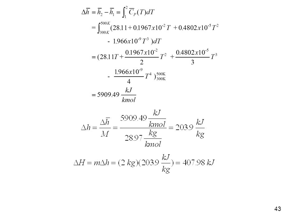
Example 2-9 Two kilograms of air are heated from 300 to 500 K. Find the change in enthalpy by assuming a. Empirical specific heat data from Table A-2(c). b. Air tables from Table A-17. c. Specific heat at the average temperature from Table A-2(c). d. Use the 300 K value for the specific heat from Table A-2(a). a.Table A-2(c) gives the molar specific heat at constant pressure for air as The enthalpy change per unit mole is
. b. Air tables from Table A-17. c. Specific heat at the average temperature from Table A-2(c). d. Use the 300 K value for the specific heat from Table A-2(a). a.Table A-2(c) gives the molar specific heat at constant pressure for air as. The enthalpy change per unit mole is.")
44
b. Using the air tables, Table A-17, at T1 = 300 K, h1 = 300
b.Using the air tables, Table A-17, at T1 = 300 K, h1 = kJ/kg and at T2 = 500 K, h2 = kJ/kg The results of parts a and b would be identical if Table A-17 had been based on the same specific heat function listed in Table A-2(c). c.Let’s use a constant specific heat at the average temperature. Tave = ( )K/2 = 400 K. At Tave , Table A-2 gives CP = kJ/(kgK). For CP = constant,
. c.Let’s use a constant specific heat at the average temperature. Tave = ( )K/2 = 400 K. At Tave , Table A-2 gives. CP = kJ/(kgK). For CP = constant,")
45
d.Using the 300 K value from Table A-2(a), CP = 1.005 kJ/kg- K.
For CP = constant, Extra Problem Find the change in internal energy for air between 300 K and 500 K, in kJ/kg.

46
The Systematic Thermodynamics Solution Procedure
When we apply a methodical solution procedure, thermodynamics problems are relatively easy to solve. Each thermodynamics problem is approached the same way as shown in the following, which is a modification of the procedure given in the text: Thermodynamics Solution Method Sketch the system and show energy interactions across the boundaries. Determine the property relation. Is the working substance an ideal gas or a real substance? Begin to set up and fill in a property table. Determine the process and sketch the process diagram. Continue to fill in the property table. Apply conservation of mass and conservation of energy principles. Bring in other information from the problem statement, called physical constraints, such as the volume doubles or the pressure is halved during the process. Develop enough equations for the unknowns and solve.

47
Example 4-7 A tank contains nitrogen at 27C. The temperature rises to 127C by heat transfer to the system. Find the heat transfer and the ratio of the final pressure to the initial pressure. System: Nitrogen in the tank. 2 T2=127C T1= 27C P V 1 P-V diagram for a constant volume process Nitrogen gas System boundary Property Relation: Nitrogen is an ideal gas. The ideal gas property relations apply. Let’s assume constant specific heats. (You are encouraged to rework this problem using variable specific heat data.) Process: Tanks are rigid vessels; therefore, the process is constant volume. Conservation of Mass:
 Process: Tanks are rigid vessels; therefore, the process is constant volume. Conservation of Mass:")
48
Conservation of Energy:
Using the combined ideal gas equation of state, Since R is the particular gas constant, and the process is constant volume, Conservation of Energy: The first law closed system is For nitrogen undergoing a constant volume process (dV = 0), the net work is (Wother = 0)
, the net work is (Wother = 0)")
49
Using the ideal gas relations with Wnet = 0, the first law becomes (constant specific heats)
The heat transfer per unit mass is Example 4-8 Air is expanded isothermally at 100C from 0.4 MPa to 0.1 MPa. Find the ratio of the final to the initial volume, the heat transfer, and work. System: Air contained in a piston-cylinder device, a closed system

50
Process: Constant temperature
P-V diagram for T= constant P V 1 2 Air Wb T = const. System boundary Property Relation: Assume air is an ideal gas and use the ideal gas property relations with constant specific heats. Conservation of Energy: The system mass is constant but is not given and cannot be calculated; therefore, let’s find the work and heat transfer per unit mass.

51
Work Calculation: Conservation of Mass: For an ideal gas in a closed system (mass = constant), we have Since the R's cancel and T2 = T1

52
Then the work expression per unit mass becomes
The net work per unit mass is Now to continue with the conservation of energy to find the heat transfer. Since T2 = T1 = constant, So the heat transfer per unit mass is

53
The heat transferred to the air during an isothermal expansion process equals the work done.
Examples Using Variable Specific Heats Review the solutions in Chapter 4 to the ideal gas examples where the variable specific heat data are used to determine the changes in internal energy and enthalpy.

54
Extra Problem for You to Try:
An ideal gas, contained in a piston-cylinder device, undergoes a polytropic process in which the polytropic exponent n is equal to k, the ratio of specific heats. Show that this process is adiabatic. When we get to Chapter 7 you will find that this is an important ideal gas process. Internal Energy and Enthalpy Changes of Solids and Liquids We treat solids and liquids as incompressible substances. That is, we assume that the density or specific volume of the substance is essentially constant during a process. We can show that the specific heats of incompressible substances (see Chapter 12) are identical. The specific heats of incompressible substances depend only on temperature; therefore, we write the differential change in internal energy as
 are identical. The specific heats of incompressible substances depend only on temperature; therefore, we write the differential change in internal energy as.")
55
and assuming constant specific heats, the change in internal energy is
Recall that enthalpy is defined as The differential of enthalpy is For incompressible substances, the differential enthalpy becomes Integrating, assuming constant specific heats For solids the specific volume is approximately zero; therefore,

56
For liquids, two special cases are encountered:
1.Constant-pressure processes, as in heaters (P = 0) 2.Constant-temperature processes, as in pumps (T = 0) We will derive this last expression for h again once we have discussed the first law for the open system in Chapter 5 and the second law of thermodynamics in Chapter 7. The specific heats of selected liquids and solids are given in Table A-3.
 2.Constant-temperature processes, as in pumps (T = 0) We will derive this last expression for h again once we have discussed the first law for the open system in Chapter 5 and the second law of thermodynamics in Chapter 7. The specific heats of selected liquids and solids are given in Table A-3.")
57
Example 4-8 Incompressible Liquid
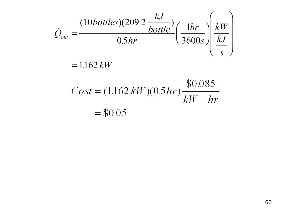
A two-liter bottle of your favorite beverage has just been removed from the trunk of your car. The temperature of the beverage is 35C, and you always drink your beverage at 10C. How much heat energy must be removed from your two liters of beverage? You are having a party and need to cool 10 of these two-liter bottles in one-half hour. What rate of heat removal, in kW, is required? Assuming that your refrigerator can accomplish this and that electricity costs 8.5 cents per kW-hr, how much will it cost to cool these 10 bottles? System: The liquid in the constant volume, closed system container Qout The heat removed System boundary My beverage

58
Property Relation: Incompressible liquid relations, let’s assume that the beverage is mostly water and takes on the properties of liquid water. The specific volume is m3/kg, C = 4.18 kJ/kgK. Process: Constant volume Conservation of Mass: Conservation of Energy: The first law closed system is

59
Since the container is constant volume and there is no “other” work done on the container during the cooling process, we have The only energy crossing the boundary is the heat transfer leaving the container. Assuming the container to be stationary, the conservation of energy becomes The heat transfer rate to cool the 10 bottles in one-half hour is

Similar presentations


>")
.>")


