Download presentation
Presentation is loading. Please wait.

1
Team Members John Henderson Curt LaBarge Greg Pearson Yixin Qiao Client/Advisor Steve Holland (ISU Canoe and Kayak Club)
")
2
Iowa flow levels change often Current gauging strategies are inadequate – High Maintenance – At threat of cancelation – Cover a limited amount of streams and rivers Canoers and Kayakers need easy access to flow data to accurately plan trips Some waterways are currently not monitored Photo Credits: ISU Canoe and Kayak Club

3
Design and build a low-cost stream depth gauge The gauge should be: – Affordable – Self contained – Robust in the environment – Capable of operating for long period of time – Capable of transmitting measurements wirelessly

4
Current gauging done mostly by United States Geological Survey These gauges are expensive – $5,000/yr to maintain Complex Design – Stilling basin – Two story structure – Under ground pipes – Electronic recorder Typical USGS Gauge Design Photo Credit: USGS http://ga.water.usgs.gov/edu/streamflow1.htmlhttp://ga.water.usgs.gov/edu/streamflow1.html

5
Total Price of Materials < $500 Measurement Accuracy: 1inch Operating Temp: -5°C to 70°C Survivable Temp: -40°C to 70°C Daily data transmission Power save during winter

6
Low maintenance cost Long battery life – Minimum: 1 yr Rugged design Weatherproof Low power consumption

7
Semester 1 – Conducted research – Identified design requirements – Rough schematic design – Purchased major components Semester 2 – Purchased new parts as needed – Programmed micro-controller – Implemented cell module – Comprehensive testing of equipment – PCB design

9
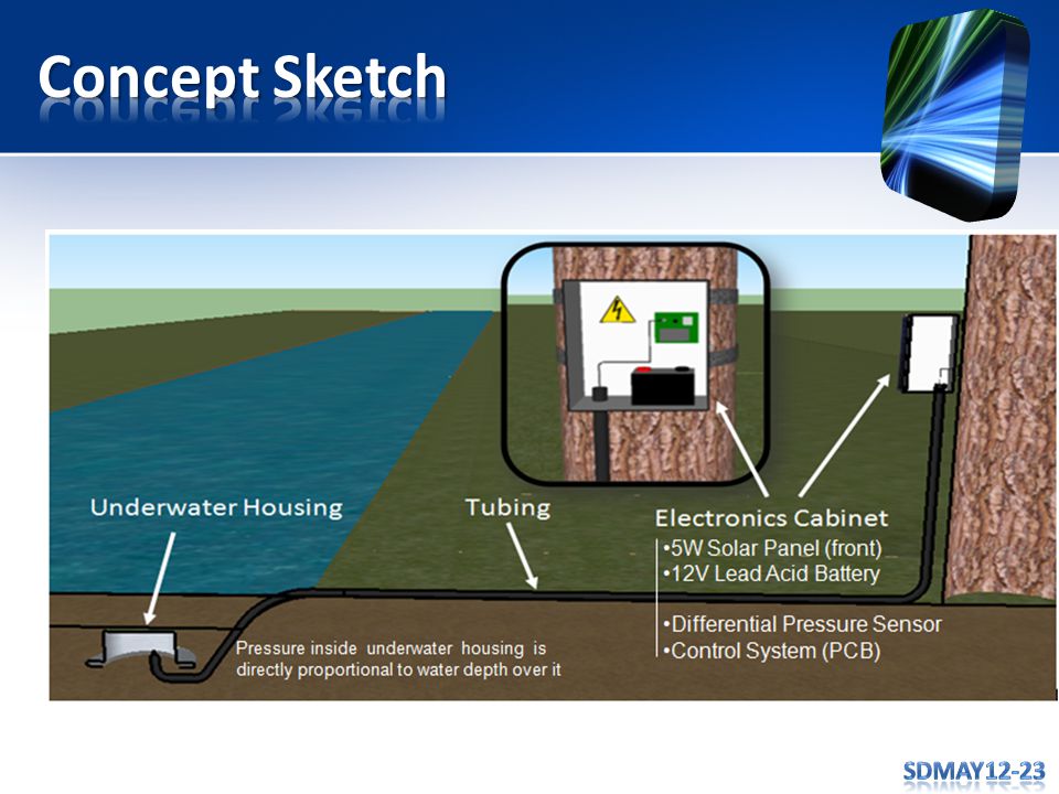
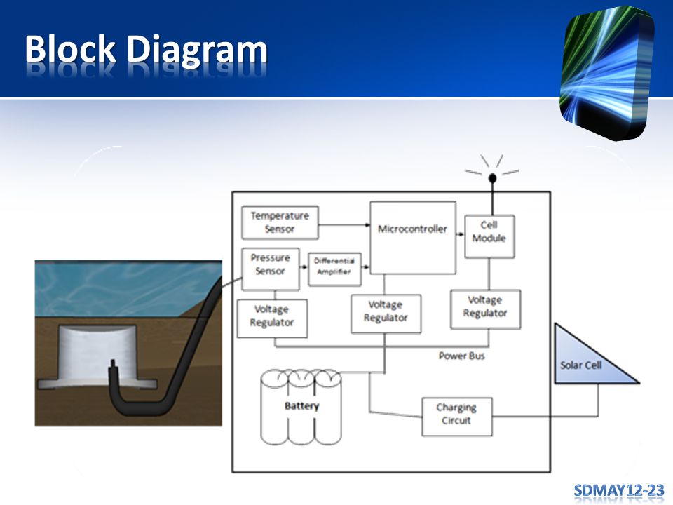
AIR Water level is proportional to air pressure inside cylinder As water depth over cylinder increases, so does air pressure Housing and tubing buried under a sand bank for added protection against floating debris Tube to Pressure Sensor

10
Atmel ATMega128 Telit GM-862 Freescale MPX2050

11
Voltage Regulators 5 W Solar Panel Charging Circuit Two 6 Volt Batteries

12
State Machine

14
Level Shifters – MC14504BDR2GOSCT-ND Voltage Regulators – LT1764AEQ#PBF (Cell Modem) – TPS7A1650DGNR (Microcontroller) Instrumentation Amplifier
 – TPS7A1650DGNR (Microcontroller) Instrumentation Amplifier")
15
Watchdog timer Debugging – UART USB – LEDs – Buzzer AT Commands Consolidated States

16
4 LEDs on the CEREBOT II board To display the values by binary number – Indicates the number of digits of the variable – Display from the least significant digit to most significant digit Helped in testing temperature sensor and pressure sensor

17
Used for power saving 6 sleep modes – Idle, ADC Noise Reduction, Power-down, Power-save, Standby, Extended Standby Atmega128 doesn’t support Watchdog interrupt Idle mode with Timer0

18
Find the output of 32ᵒF Cutting point – When lower than 32ᵒF, go to sleep – When higher than 32ᵒF, measure the pressure Temperature chamber was used to find cut-off point.

19
Instrumental amplifier to obtain the difference of the two outputs – With gain of 4000 (for testing) – Max output of the amplifier is 5V Measures from 2 to 15 inches Accurate to 1 inch Tested with a 2-liter bottle with 9-inch hight
 – Max output of the amplifier is 5V Measures from 2 to 15 inches Accurate to 1 inch Tested with a 2-liter bottle with 9-inch hight")
20
Cell Modem Tests happened in two phases 1.Testing AT commands with a computer via USB. 2.Testing UART communication between microcontroller and Cell Modem

21
Cell Modem is controlled via different AT Commands First Testing stage tested the usage of these AT commands: AT AT+CREG=? AT+CMGF=1 AT+CMGS=“ ” AT#SHDN

22
Second Phase of Testing involved UART Communication between the Cell Modem – 3V logic Microcontroller – 5V logic Voltage level shifter

23
We used USB to Serial device that could read UART communication to test. Showed us transmitting signal to make sure signal was correct

24
For the full Software Testing, we breadboarded all components together. System could run through each state in the State machine. Each component worked together with everything assembled

25
Our device performs its intended purpose: To measures and transmit an accurate water height The device could be easily expanded upon: Database to store river height information

26
We learned that communication is key to getting things done properly. The project gave us a more realistic view of what problem solving is like Having the right tools make getting the job done exponentially faster

27
Brief Summary Stream depth gauge Components – Pressure sensor – Microcontroller – Cell Module – Power Circuitry ? ? ? ? ? ?

Similar presentations


>")
 Adam McCauley (ECE) Shawn Kachnowski.>")


 Group Leader: Tomas Mullins Communicator: Casey Liebl Webmaster: Shiya Liu Team Members: Andrew Gurik & Qiao.>")

 Monitors Sd-May11-20 Betty Nguyen Scott Mertz David Hansen Ashley Polkinghorn Advisors Joseph Shinar.>")


