Download presentation
Presentation is loading. Please wait.

1
4. RUP 2007

2
What Is the Rational Unified Process?
The RUP is a software development approach that is iterative, architecture-centric, and use-case-driven The RUP is a well-defined and well-structured software engineering process The RUP is also a process product that provides you with a customizable process framework for software engineering

3
Use Case driven A use case is a piece of functionality in the system that gives a user a result of value Use cases capture functional requirements Use case answers the question: What is the system supposed to do for the user?

4
Architecture centric Architecture centric
similar to architecture for building a house Embodies the most significant static and dynamic aspects of the system Influenced by platform, OS, DBMS etc. Primarily serves the realization of use cases

5
Iterative and Incremental
commercial projects continue many months and years to be most effective - break the project into iterations Every iteration - identify use cases,create a design, implement the design Every iteration is a complete development process

6
Waterfall and Iterative Process

7
Iterative and Incremental Development Process
Iteration No. 1 2 3 867 868 Test whole Integrate Test units Implement Design Analyze requirements

8
Classification of iterations (Classically called “phases”)
UP Terminology (1) Classification of iterations Individual iteration Inception Elaboration Construction Transition Prelim. iterations Iter. #1 Iter. #n Iter. #n+1 Iter. #m Iter. #m+1 Iter. #k .. ….. … Requirements Analysis UP calls these “disciplines” (Classically called “phases”) Design Implemen- tation Test
 Classification of iterations. Individual iteration. Inception. Elaboration. Construction. Transition. Prelim. iterations. Iter. #1. Iter. #n. Iter. #n+1. Iter. #m. Iter. #m+1. Iter. #k. .. ….. … Requirements. Analysis. UP calls these. disciplines (Classically called phases ) Design. Implemen- tation. Test.")
9
The Unified Process Look at the whole process Life cycle Artifacts
Disciplines (Workflows) Phases Iterations
 Phases. Iterations.")
10
UP Phases: Classification of Iterations
Inception iterations: preliminary interaction with stakeholders primarily customer users financial backers etc. Elaboration iterations : finalization of what’s wanted and needed; set architecture baseline Construction iterations : results in initial operational capability Transition iterations : completes product release

11
Requirements analysis
UP Terminology (2) Requirements Analysis Design Implementation Test Requirements analysis UP Terminology Classical Terminology Integration
 Requirements. Analysis. Design. Implementation. Test. Requirements analysis. UP Terminology. Classical Terminology. Integration.")
12
Unified Process Matrix
Inception Elaboration Construction Transition Prelim. iterations Iter. #1 Iter. #n Iter. #n+1 Iter. #m Iter. #m+1 Iter. #k .. ….. ….. Requirements Analysis Amount of effort expended on the requirements phase during the first Construction iteration Design Implemen- tation Test

13
Inception Phase Overriding goal is obtaining buy-in from all interested parties Initial requirements capture Cost Benefit Analysis Initial Risk Analysis Project scope definition Defining a candidate architecture Development of a disposable prototype Initial Use Case Model (10% - 20% complete) First pass at a Domain Model
 First pass at a Domain Model.")
14
Elaboration Phase Requirements Analysis and Capture Use Case Analysis
Use Case (80% written and reviewed by end of phase) Use Case Model (80% done) Scenarios Sequence and Collaboration Diagrams Class, Activity, Component, State Diagrams Glossary (so users and developers can speak common vocabulary) Domain Model to understand the problem: the system’s requirements as they exist within the context of the problem domain Risk Assessment Plan revised Architecture Document
 Use Case Model (80% done) Scenarios. Sequence and Collaboration Diagrams. Class, Activity, Component, State Diagrams. Glossary (so users and developers can speak common vocabulary) Domain Model. to understand the problem: the system’s requirements as they exist within the context of the problem domain. Risk Assessment Plan revised. Architecture Document.")
15
Construction Phase Focus is on implementation of the design:
cumulative increase in functionality greater depth of implementation (stubs fleshed out) greater stability begins to appear implement all details, not only those of central architectural value analysis continues, but design and coding predominate
 greater stability begins to appear. implement all details, not only those of central architectural value. analysis continues, but design and coding predominate.")
16
Transition Phase The transition phase consists of the transfer of the system to the user community It includes manufacturing, shipping, installation, training, technical support and maintenance Development team begins to shrink Control is moved to maintenance team Alpha, Beta, and final releases Software updates Integration with existing systems (legacy, existing versions, etc.)
")
17
Elaboration Phase in Detail
Use Case Analysis Find and understand 80% of architecturally significant use cases and actors Prototype User Interfaces Prioritize Use Cases within the Use Case Model Detail the architecturally significant Use Cases (write and review them) Prepare Domain Model of architecturally significant classes, and identify their responsibilities and central interfaces (View of Participating Classes)
 Prepare Domain Model of architecturally significant classes, and identify their responsibilities and central interfaces (View of Participating Classes)")
18
Use Case Analysis What is a Use Case?
A sequence of actions a system performs that yields a valuable result for a particular actor. What is an Actor? A user or outside system that interacts with the system being designed in order to obtain some value from that interaction Use Cases describe scenarios that describe the interaction between users of the system and the system itself. Use Cases describe WHAT the system will do, but never HOW it will be done.

19
Use Cases Describe Function not Form
Use Cases describe WHAT the system should do, but never HOW it will be done Use cases are Analysis products, not design products

20
Benefits of Use Cases Use cases are the primary vehicle for requirements capture in RUP Use cases are described using the language of the customer (language of the domain which is defined in the glossary) Use cases provide a contractual delivery process (RUP is Use Case Driven) Use cases provide an easily-understood communication mechanism When requirements are traced, they make it difficult for requirements to fall through the cracks Use cases provide a concise summary of what the system should do at an abstract (low modification cost) level.
 Use cases provide a contractual delivery process (RUP is Use Case Driven) Use cases provide an easily-understood communication mechanism. When requirements are traced, they make it difficult for requirements to fall through the cracks. Use cases provide a concise summary of what the system should do at an abstract (low modification cost) level.")
21
Difficulties with Use Cases
As functional decompositions, it is often difficult to make the transition from functional description to object description to class design Reuse at the class level can be hindered by each developer “taking a Use Case and running with it”. Since UCs do not talk about classes, developers often wind up in a vacuum during object analysis, and can often wind up doing things their own way, making reuse difficult Use Cases make stating non-functional requirements difficult (where do you say that X must execute at Y/sec?) Testing functionality is straightforward, but unit testing the particular implementations and non-functional requirements is not obvious
 Testing functionality is straightforward, but unit testing the particular implementations and non-functional requirements is not obvious.")
22
Analysis Model In Analysis, we analyze and refine the requirements described in the Use Cases in order to achieve a more precise view of the requirements, without being overwhelmed with the details Again, the Analysis Model is still focusing on WHAT we’re going to do, not HOW we’re going to do it (Design Model). But what we’re going to do is drawn from the point of view of the developer, not from the point of view of the customer Whereas Use Cases are described in the language of the customer, the Analysis Model is described in the language of the developer: Boundary Classes Entity Classes Control Classes
. But what we’re going to do is drawn from the point of view of the developer, not from the point of view of the customer. Whereas Use Cases are described in the language of the customer, the Analysis Model is described in the language of the developer: Boundary Classes. Entity Classes. Control Classes.")
23
Why spend time on the Analysis Model, why not just “face the cliff”?
By performing analysis, designers can inexpensively come to a better understanding of the requirements of the system By providing such an abstract overview, newcomers can understand the overall architecture of the system efficiently, from a ‘bird’s eye view’, without having to get bogged down with implementation details. The Analysis Model is a simple abstraction of what the system is going to do from the point of view of the developers. By “speaking the developer’s language”, comprehension is improved and by abstracting, simplicity is achieved Nevertheless, the cost of maintaining the AM through construction is weighed against the value of having it all along.

24
Boundary Classes Boundary classes are used in the Analysis Model to model interactions between the system and its actors (users or external systems) Boundary classes are often implemented in some GUI format (dialogs, widgets, beans, etc.) Boundary classes can often be abstractions of external APIs (in the case of an external system actor) Every boundary class must be associated with at least one actor:
 Boundary classes can often be abstractions of external APIs (in the case of an external system actor) Every boundary class must be associated with at least one actor:")
25
4+1 Architecture

26
4+1 Architecture Use-Case View, which contains use-cases and scenarios that encompasses architecturally significant behavior, classes, or technical risks. It is a subset of the total use-case model. Logical View, which contains the most important design classes and their organization into packages and subsystems, and the organization of these packages and subsystems into layers. It can also contain some use case realizations. It is a subset of the total design model

27
4+1 Architecture Implementation View, which contains an overview of the implementation model and its organization in terms of modules into packages and layers. The allocation of packages and classes (from the Logical View) to the packages and modules of the Implementation View is also described. It is a subset of the total implementation model Process View, which contains the description of the tasks (process and threads) involved, their interactions and configurations, and the allocation of design objects and classes to tasks. This view need only be used if a system has a significant degree of concurrency
 to the packages and modules of the Implementation View is also described. It is a subset of the total implementation model. Process View, which contains the description of the tasks (process and threads) involved, their interactions and configurations, and the allocation of design objects and classes to tasks. This view need only be used if a system has a significant degree of concurrency.")
28
4+1 Architecture Deployment View, which contains the description of the various physical nodes for the most typical platform configurations, and the allocation of tasks (from the Process View) to the physical nodes. This view shows how a system is distributed.
 to the physical nodes. This view shows how a system is distributed.")
29
Architectural focus The architecture concerns itself only with some specific aspects: The structure of the model - the organizational patterns, e.g. layering The essential elements - critical use cases, main classes, common mechanisms, and so on, as opposed to all the elements present in the model A few key scenarios showing the main control flows throughout the platform The services, to capture modularity, optional features, product-line aspects

30
RUP— The Approach

31
Underlying Principles of the RUP Approach
Attack major risks early and continuously or they will attack you Ensure that you deliver value to your customer

32
The Spirit of the RUP – Essential Principles
Attack major risks early and continuously…or they will attack you Ensure that you deliver value to your customer Stay focused on executable software Accommodate change early in the project Baseline an executable architecture early on Build your system with components Make quality a way of life, not an afterthought

33
RUP and Iterative Development

34
The Iterative Approach
It accommodates changing requirements Integration is not one "big bang" at the end of a project Risks are usually discovered or addressed during early integrations Management has a means of making tactical changes to the product Reuse is facilitated Defects can be found and corrected over several iterations It is a better use of project personnel Team members learn along the way The development process itself is improved and refined along the way

35
The Phased Iterative Approach – example
In the first iteration we will do 90% analysis, 10% design In the second iteration we will do 30% analysis, 50% design, 20% coding In the third iteration we will do 10% analysis, 30% design, 60% coding In the fourth iteration we will do 10% design, 50% coding, 40% testing and bug fixing In the fifth iteration we will do 50% testing and bug fixing, 30% integration, 20% deployment

36
Iterative Development with Incremental Delivery
First, we go through several iterations of analysis and design, until we are pretty sure these phases are mostly complete. We can then select the content and schedule of the increments to be developed. Let’s have identified three increments A, B and C, to be delivered in this order to the users. For increment A, we iterate through all required phases, until the software can be released. We expect to rework the analysis and design very little. For increment B, we iterate through all required phases, until the software can be released. We expect almost no analysis or design work. For increment C, we iterate through all required phases, until the software can be released. The amount of analysis and (architectural) design decreases in each step. The process delivers functionality after the second, third and fourth steps.
 design decreases in each step. The process delivers functionality after the second, third and fourth steps.")
37
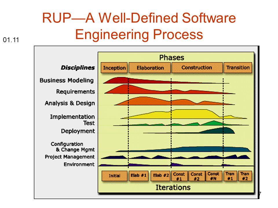
RUP—A Well-Defined Software Engineering Process
01.11
38
The RUP—A Well-Defined Software Engineering Process
Dynamic structure – time dimension Static structure – describes how process elements—activities, disciplines, artifacts, and roles—are logically grouped into core process disciplines

39
Basic Concepts in the Rational Unified Process

40
The Dynamic Structure of the Rational Unified Process

41
RUP Lifecycle

42
RUP Lifecycle (detail)
")
43
Iteration

44
The Dynamic Structure of the Rational Unified Process
Inception Elaboration Construction Transition

45
The Four Phases

46
Objectives of the Phases
Inception: Understand what to build Elaboration: Understand how to build it Construction: Build a beta version of the product Transition: Build the final version of the product time

47
Milestones

48
Resources

49
Models

50
Inception

51
Inception Establish a good understanding of what system to build by getting a high-level understanding of all the requirements and establishing the scope of the system Mitigate many of the business risks, Produce the business case for building the system Get buy-in from all stakeholders on whether to proceed with the project

52
Inception Phase Objectives: Milestone:
Understand the scope of the project Build the business case Get stakeholder buy-in to move ahead Milestone: Lifecycle Objective Milestone (LCO)
")
53
Relative cost to fix defect at different lifecycle phases

54
Stakeholder Needs

55
Early Lifecycle Activities

56
Detailing and Review Activities for Use Cases

57
Software Requirements

58
Derived business rules at the summary meeting

59
Elaboration

60
Elaboration Take care of many of the most technically difficult tasks:
Design, implement, test, and baseline an executable architecture, including subsystems, their interfaces, key components, and architectural mechanisms, such as how to deal with inter-process communication or persistency Address major technical risks, such as resource contention risks, performance risks, and data security risks, by implementing and validating actual code

61
Elaboration Phase Objectives: Milestone:
Mitigate major technical risks Create a baselined architecture Understand what it takes to build the system Milestone: Lifecycle Architecture Milestone (LCA)
")
62
Workflow for Architectural Analysis

63
Use-Case Analysis activity

64
The steps of use case analysis

65
Use Case Design activity

66
The steps of Use Case Design

67
Requirements Management: Discipline Details

68
Workflow Detail: Analyze the Problem

69
Workflow Detail: Understand Stakeholder Needs

70
Workflow Detail: Define the System

71
Workflow Detail: Manage the Scope of the System

72
Workflow Detail: Refine the System Definition

73
Workflow Detail: Manage Changing Requirements

74
Requirements Artifacts

75
Construction

76
Construction Do most of the implementation as you move from an executable architecture to the first operational version of your system Deploy several internal and alpha releases to ensure that the system is usable and addresses user needs End the phase by deploying a fully functional beta version of the system, including installation and supporting documentation and training material (although the system will likely still require tuning of functionality, performance, and overall quality)
")
77
Construction Phase Objective: Milestone:
Build the first operational version of the product Milestone: Initial Operational Capability Milestone (IOC)
")
78
Design artifacts drive development of source code

79
Transition

80
Transition Ensure that software addresses the needs of its users
This includes testing the product in preparation for release and making minor adjustments based on user feedback At this point in the lifecycle, user feedback focuses mainly on fine-tuning the product, configuration, installation, and usability issues; all the major structural issues should have been worked out much earlier in the project lifecycle

81
Transition Phase Objective: Milestone:
Build the final version of the product and deliver it to the customer Milestone: Product Release Milestone (PR)
")
82
The Static Structure of the Rational Unified Process

83
RUP—A Well-Defined Software Engineering Process

84
The Static Structure of the Rational Unified Process

85
Four Key Modeling Elements of the RUP
Roles. The who Activities. The how Artifacts. The what Workflows. The when

86
Roles A role is like a "hat" that an individual (or group) wears during a project. One individual may wear many different hats. This is an important point because it is natural to think of a role as an individual on the team, or as a fixed job title, but in the RUP the roles simply define how the individuals should do the work, and they specify the competence and responsibility that the individual(s) playing that role should have. A person usually performs one or more roles, and several people can perform the same role.
 playing that role should have. A person usually performs one or more roles, and several people can perform the same role.")
87
People and Workers John

88
Activities An activity of a specific role is a unit of work that an individual in that role may be asked to perform The activity has a clear purpose, usually expressed in terms of creating or updating some artifacts, such as a model, a component, or a plan Each activity is assigned to a specific role An activity generally takes a few hours to a few days to complete, usually involves one person, and affects one or only a small number of artifacts An activity should be usable as an element of planning and progress; if it is too small, it will be neglected, and if it is too large, progress would have to be expressed in terms of an activity's parts Activities may be repeated several times on the same artifact—especially when going from one iteration to another, refining and expanding the system—by the same role, but not necessarily by the same individual

89
Steps Activities are broken down into steps, which fall into three main categories: Thinking steps, where the person playing the role understands the nature of the task, gathers and examines the input artifacts, and formulates an outcome Performing steps, where the role creates or updates some artifacts Reviewing steps, where the role inspects the results against some criteria Not all steps are necessarily performed each time an activity is invoked, so steps can be expressed in the form of alternate flows.

90
Artifacts An artifact is a piece of information that is produced, modified, or used by a process Artifacts are the tangible project elements: things the project produces or uses while working toward the final product Artifacts are used as input by roles to perform an activity and are the result or output of other activities

91
Artifacts Artifacts may take various shapes or forms:
A model, such as the Use-Case Model or the Design Model A model element, that is, an element within a model, such as a class, a use case (UC), or a subsystem A document, such as the Vision or Business Case Source code Executables, such as an executable Prototype
, or a subsystem. A document, such as the Vision or Business Case. Source code. Executables, such as an executable Prototype.")
92
Workflows A mere listing of all roles, activities, and artifacts does not quite constitute a process You need a way to describe meaningful sequences of activities that produce some valuable result and to show interactions between roles—this is exactly what workflows do

93
Workflows Workflows come in different shapes and forms
Disciplines, which are high-level workflows Workflow Details, which are workflows within a discipline

94
Disciplines All process elements—roles, activities, artifacts, and the associated concepts, guidelines, and templates—are grouped into logical containers called Disciplines: Business modeling Requirements management Analysis and design Implementation Deployment Test Project management Change management Environment

95
The Spirit of the RUP: Guidelines for Success

96
Attack Major Risks Early and Continuously, or They Will Attack You

97
Attack Major Risks Early and Continuously, or They Will Attack You
At the beginning of each iteration, the RUP advises you to make, or revise, a list of top risks Prioritize the risk list Risks need to be addressed from multiple perspectives such as requirements design, and testing For each of these perspectives, start with a coarse solution and successively detail it to diminish the risk Then decide what you need to do to address, typically, the top three to five risks

98
Attack Major Risks Early

99
Ongoing Focus on Risk Addressing the most critical risks early in the life cycle. The goal is to mitigate risks to the greatest extent possible during each iteration, so each iteration poses fewer risks of less importance than its predecessors.

100
Ongoing Focus on Risk (cont.)
Three categories of risks useful in discussing the Unified Process. Technical risks Architectural risks Requirements risk

101
Technical risks Technical risks are those associated with the various technologies that will come into play during the project and with issues such as performance and the reliability, scalability, etc. The process doesn't specifically address technical risks; however, the emphasis on architecture reflects the principle that the team should address technical risks early, before coding starts.

102
Architectural risks Architectural risks are those associated with the ability of the architecture to serve as a strong foundation of the system and also be sufficiently resilient and adaptable to the addition of features in future releases of the system. Risks associated with "make versus buy" decisions are also part of this category. The process addresses architectural risks by defining activities that involve analyzing, designing, and implementing the architecture, and by defining a number of other activities that include keeping the architecture description up to date so it can assume its place front and center within the development effort.

103
Requirements risk Requirements risk is the risk of not building the right system — the system that the customers are paying for — by not understanding the requirements and not using associated use cases to drive development. The process addresses requirements risk with activities specifically defined to facilitate the discovery and negotiation of requirements and with its premise that use cases should drive all aspects of development.

104
Ensure That You Deliver Value to Your Customer
Use-case-driven approach Use cases are a way of capturing functional requirements Since they describe how a user will interact with the system, they are easy for a user to relate to And since they describe the interaction in a time-sequential order, it is easy for both users and analysts to identify any holes in the use case A use case can almost be considered a section in the future user manual for the system under development, but it is written with no knowledge about the specific user interface Use cases force you to stay externally focused on the user's perspective, and they allow you to validate the design and implementation with respect to the user requirements

105
Accommodate Change Early in the Project
We group changes into four categories: Cost of change to the business solution Cost of change to the architecture Cost of change to the design and implementation Cost of change to the scope

106
Cost of change RUP

107
Cost of change to the business solution
There is a fair amount of flexibility in making this type of modification during the Inception phase, but costs escalate as you move into the Elaboration phase This is why you force an agreement on the vision for the system in Inception

108
Cost of change to the architecture
You can make fairly significant architectural changes at low cost until the end of Elaboration After that, significant architectural changes become increasingly costly, which is why the architecture must be baselined at the end of Elaboration

109
Cost of change to the design and implementation
Because of the component-based approach, these types of changes are typically localized and can hence be made at fairly low cost throughout the Construction phase These types of changes are, however, increasingly expensive in the Transition phase, which is why you typically introduce "feature freeze" at the end of Construction

110
Cost of change to the scope
The cost of cutting scope—and hence postponing features to the next release—is relatively inexpensive throughout the project, if done within limits Scope cutting is greatly facilitated by iterative development; project managers should use it as a key tool to ensure on-time project delivery

111
Cost of change

112
Baseline an Executable Architecture Early On
The architecture comprises the software system's most important building blocks and their interfaces, that is, the subsystem, the interfaces of the subsystems, and the most important components and their interfaces The architecture provides a skeleton structure of the system, comprising perhaps 10 to 20 percent of the final amount of code

113
Baseline an Executable Architecture Early On
A strict layered architecture states that design elements (classes, components, packages, subsystems) only use the services of the layer below them. Services can include event-handling, error-handling, database access, and so forth. It contains more palpable mechanisms, as opposed to raw operating system level calls documented in the bottom layer.
 only use the services of the layer below them. Services can include event-handling, error-handling, database access, and so forth. It contains more palpable mechanisms, as opposed to raw operating system level calls documented in the bottom layer.")
114
Build Your System with Components
Functional Decomposition Architecture vs. Component-Based Architecture

115
Quality

116
Adopting the Rational Unified Process

117
The RUP—A Customizable Process Product
Best practices The RUP comes with a library of best practices, produced by IBM Software and its partners These best practices are continually evolving and cover a broader scope than this book can cover The best practices are expressed in the form of phases, roles, activities, artifacts, and workflows

118
The RUP—A Customizable Process Product
Process delivery tools The RUP is literally at the developers' fingertips because it is delivered online using Web technology, rather than using books or binders This delivery allows the process to be integrated with the many software development tools in the Rational Suite and with any other tools so developers can access process guidance within the tool they are using

119
The RUP—A Customizable Process Product
Configuration tools The RUP's modular and electronic form allows it to be tailored and configured to suit the specific needs of a development organization

120
The RUP—A Customizable Process Product
Process authoring tools Rational Process Workbench (RPW) is a process authoring tool, allowing you to capture your own best practices into the RUP format
 is a process authoring tool, allowing you to capture your own best practices into the RUP format.")
121
The RUP—A Customizable Process Product
Community/Marketplace The Rational Developer Network (RDN) online community allows users to exchange experiences with peers and experts, and provides access to the latest information in terms of artifacts, articles, or additional RUP content
 online community allows users to exchange experiences with peers and experts, and provides access to the latest information in terms of artifacts, articles, or additional RUP content.")
122
“Right-size" the Process
Right-sizing: Allow projects to "right-size" the process they use; that is, allow projects to use "just enough" process. Users should be able to start with a small process, and as project needs expand, to grow the process to address those needs. Process guidance: Make a wide array of process guidance available to users, including specific guidance on how to develop software for a variety of architectures, target devices, and hardware/software platforms.

123
Configuring the RUP Producing a RUP Process Configuration
The RUP process framework contains a vast amount of guidance, artifacts, and roles. Because no project should use all of these artifacts, you need to specify a subset of the RUP to use for your project. This is done by selecting or producing a RUP Process Configuration, which constitutes a complete process from the perspective of a particular project's requirements. You can use one of the ready-made configurations as is or use a ready-made configuration as a starting point or create a process configuration from scratch.

124
Producing a RUP Process Configuration
A RUP Process Component is a coherent, quasi-independent "chunk" or module of process knowledge that can be named, packaged, exchanged, and assembled with other process components. A RUP Library is a collection of Process Components out of which a set of RUP Process Configurations may be "compiled" with RUP Builder. New Process Components can be added to a RUP Library through the means of RUP Plug-Ins. A RUP Base is a collection of Process Components meant to be extended by applying plug-ins to generate RUP Process Configurations. It resides in a RUP Library. A RUP Plug-In is a deployable unit for one or several Process Components that can be readily "dropped" onto a RUP Base to extend it. A RUP Plug-In can be compiled into a single physical file (with extension ".cfu"), allowing it to be moved around and added to a RUP Library with a compatible RUP Base. To explain this via a simple analogy, a RUP Plug-In is a set of "precompiled" RUP Process Components, ready to be "linked" into a RUP Base to create one or more RUP Configurations.
, allowing it to be moved around and added to a RUP Library with a compatible RUP Base. To explain this via a simple analogy, a RUP Plug-In is a set of precompiled RUP Process Components, ready to be linked into a RUP Base to create one or more RUP Configurations.")
125
MyRUP

126
Configurable RUP

127
Rational Process Workbench and Process Engineering Process
You create RUP Plug-Ins by using Rational Process Workbench, a process authoring tool that consists of the following: RUP Modeler. This tool allows a process engineer to visually model process elements such as activities, artifacts, roles, disciplines, and tool mentors and their relationships, and to compile them into RUP Process Components. RUP Modeler is an add-in to Rational XDE and works in conjunction with RUP Organizer. RUP Organizer. This tool allows you to associate content files to process elements such as activities, artifacts, roles, disciplines, and tool mentors, all of which comprise a Process Component, and to compile these RUP Process Components and create a RUP Plug-In with the new or modified files. The files can be examples, guidelines, or reusable assets (among others). RUP Organizer also allows you to modify Extended Help. RUP Process Library. This contains process models with all the process elements such as roles, artifacts, activities, and tool mentors defined in the RUP as well as related content files for each model element. Process Engineering Process. This provides process guidance for customizing, implementing, and improving the process, as well as templates for content authoring, such as HTML templates for descriptions and guidelines, a template for producing plug-ins, and all graphics needed for process authoring.
. RUP Organizer also allows you to modify Extended Help. RUP Process Library. This contains process models with all the process elements such as roles, artifacts, activities, and tool mentors defined in the RUP as well as related content files for each model element. Process Engineering Process. This provides process guidance for customizing, implementing, and improving the process, as well as templates for content authoring, such as HTML templates for descriptions and guidelines, a template for producing plug-ins, and all graphics needed for process authoring.")
128
Summary

129
Methods’ scopes

131
Project Management

132
Enterprise Unified Process

133
Teams Organized Around Architecture

134
When to Sign a Contract?

135
The Six UP Models (Views of the Application)
Use-case model Test model Analysis model Implementation model Design model Deployment model

Similar presentations


>")


 Explain when to use an adaptive approach to.>")


>")