Download presentation
Presentation is loading. Please wait.

1
Boiler Xpress 1 Final Presentation April 26, 2001 Kacie BurtonKevin Dahya Kerem KorayMellisa Glaser Wael NourTanya Tuinstra

2
Project Objective Write a MATLAB computer program for dynamic modeling and control system design of fixed wing aircraft Use Boiler Xpress geometry, mass, and aerodynamic data Produce stability and control derivatives Determine 4 th order TF, Q(s)/ E (s), R(s)/ R (s), and P(s)/ A (s) Determine 12 th order TF, Q(s)/ E (s), R(s)/ R (s), and P(s)/ A (s) Design 3 stability augmentation systems Pitch rate feedback to elevator to increase of Short Period mode Yaw rate feedback to rudder to increase of Dutch Roll mode Roll rate feedback to aileron to decrease time constant of roll mode
/ E (s), R(s)/ R (s), and P(s)/ A (s) Determine 12 th order TF, Q(s)/ E (s), R(s)/ R (s), and P(s)/ A (s) Design 3 stability augmentation systems Pitch rate feedback to elevator to increase of Short Period mode Yaw rate feedback to rudder to increase of Dutch Roll mode Roll rate feedback to aileron to decrease time constant of roll mode")
3
How we did it… Modified Cessna182.m to apply to the BoilerXpress Calculated control derivatives using Jan Roskam, Methods for Estimating Stability and Control Derivatives of Conventional Subsonic Airplanes 4 th order transfer functions: BoilerXpressLatSC.m BoilerXpressLongSC.m Plotted root loci 12 th order transfer functions and step responses: FlatEarth.mdl and FlatEarthAnal.m

4
How we did it… Modified DesignPitch.m, DesignYaw.m, and DesignRoll.m to use Boiler Xpress 4 th order transfer functions Varied control gain, K, to achieve design damping ratio Used 6 th order transfer functions from DesignPitch.m, DesignYaw.m, and DesignRoll.m to determine n for design damping ratio

5
Control Derivative Constants Lifting Force: C LO =0.95 C L =4.9174 C L ’ =0.3333 C Lq =5.3879 Side Force: C yO =0 C y =-0.0484 C y A =0 C y R =0.0353 C y p =-0.0056 C y R =0.7080 Reference Positions: xbar ac =0.3412 xbar cg =0.3412

6
Control Derivative Constants Pitching Moment: C mO =-0.0400 C m =-1.8448 Cm ’ =-0.6329 C mq =-2.9935 Rolling Moment: Clo=0 Cl =-0.0331 Cl A =0.8000 Cl R =0 Cl p =-0.1500 Cl R =0.2467 Yawing Moment: Cno=0 Cn =0.1100 Cn A =-0.1203 Cn R =-0.1280 Cn p =-0.1233 Cn R =-0.7214

7
Universal Block Diagram Transfer Function Gain k inputoutput + -

8
4 th Order Transfer Functions Pitch: Yaw: Roll:

9
12 th Order Transfer Functions Pitch: Yaw: Roll:

10
Root Locus for Q(s)/ E (s)
/ E (s)")
11
Root Locus for R(s)/ R (s)
/ R (s)")
12
Root Locus for P(s)/ A (s)
/ A (s)")
13
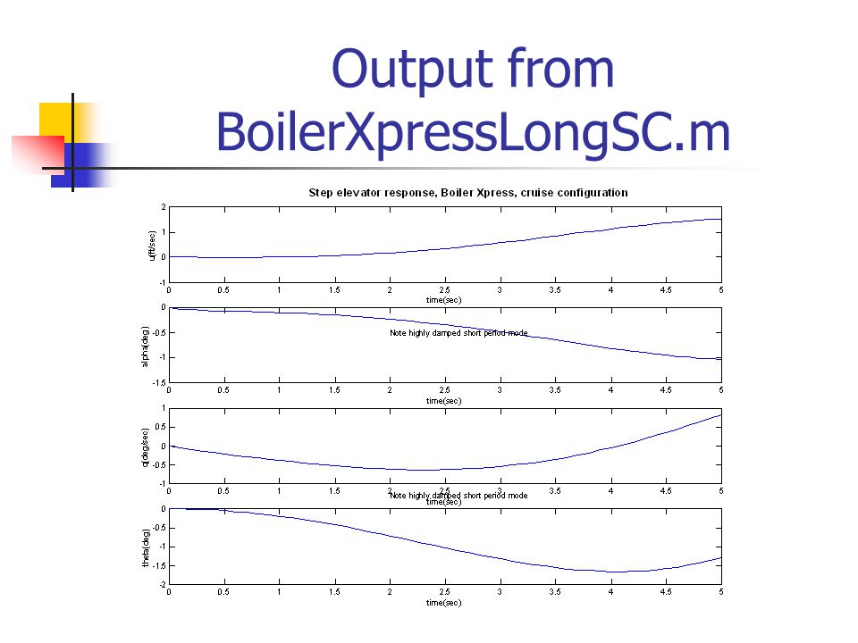
Output from BoilerXpressLongSC.m

15
Q(s)/ E (s) from FlatEarth.m
/ E (s) from FlatEarth.m")
16
R(s)/ R (s) from FlatEarth.m
/ R (s) from FlatEarth.m")
17
P(s)/ A (s) from FlatEarth.m 150 200 time (sec) Y (ft) linear sim nonlinear sim
/ A (s) from FlatEarth.m time (sec) Y (ft) linear sim nonlinear sim")
18
Pitch Stability Augmentation System Incorporated Boiler Xpress and Cessna 182 transfer functions into DesignPitch.m for system comparison Adjusted gains to meet following criteria -1.3<K<1.3 = 0.707 For K=0.2885, =0.707 Damping objective met for pitch stability

19
Pitch Stability Augmentation System Used 6 th order transfer function from DesignPitch.m to determine n for design damping ratio Pitch Root Locus

20
Yaw Stability Augmentation System Incorporated Boiler Xpress and Cessna 182 transfer functions into DesignYaw.m for system comparison Adjusted gains to meet following criteria -1.3<K<1.3 = 0.26 For K=0.35, =0.261 Damping objective met for yaw stability

21
Yaw Stability Augmentation System Used 6 th order transfer function from DesignYaw.m to determine n for design damping ratio Yaw Root Locus

22
Roll Stability Augmentation System Incorporated Boiler Xpress and Cessna 182 transfer functions into DesignRoll.m for system comparison Adjusted gains to meet following criteria -1.3<K<1.3 T = 0.1 For K=0.0001, T=0.05 Damping objective not met for roll stability

23
Roll Stability Augmentation System Used 6 th order transfer function from DesignRoll.m to determine n for design damping ratio Roll Root Locus

24
Results Pitch Stability Augmentation System K=0.2885, n =0.305 rad/sec, =0.707 Yaw Stability Augmentation System K=0.35, n =25 rad/sec, =0.261 Roll Stability Augmentation System K=0.0001, n =31 rad/sec, =0.65 T=0.05

25
Conclusions Stability and control derivatives found for Boiler Xpress 4 th and 12 th order transfer functions determined for Boiler Xpress Desired damping ratio met for pitch and yaw cases within gain limits; roll case did not meet design time constant Corresponding natural frequencies were found for each case Purpose is to achieve stable system by adding a control system

Similar presentations