Download presentation
Presentation is loading. Please wait.

1
OPTICS

2
I. IMAGES A. Definition- An image is formed where light rays originating from the same point on an object intersect on a surface or appear to intersect for the observer A. Definition- An image is formed where light rays originating from the same point on an object intersect on a surface or appear to intersect for the observer B. Real Image- formed when light rays from a common point pass though an optical system that causes them to converge and intersect at a point B. Real Image- formed when light rays from a common point pass though an optical system that causes them to converge and intersect at a point

3
1. A real image can be projected on a screen when placed where the image is formed. 1. A real image can be projected on a screen when placed where the image is formed. a. Lenses in a slide projector or a camera produce real images a. Lenses in a slide projector or a camera produce real images C. Virtual Image-formed when the light rays from a common point pass through or are reflected by an optical system that causes them to diverge and appear to come to a single point.

4
1. cannot be projected on a screen because no light from the object actually reaches the point where the image appears to be located 1. cannot be projected on a screen because no light from the object actually reaches the point where the image appears to be located a. Example Reflection in a plane mirror. The rays reaching the observers eyes actually come from the object. They are reflected by the mirror in such a way that they appear to come from the image a. Example Reflection in a plane mirror. The rays reaching the observers eyes actually come from the object. They are reflected by the mirror in such a way that they appear to come from the image

5
EACH RAY IS REFLECTED IN A REGULAR WAY ( MEANING THAT THE ANGLE OF REFLECTION EQUALS THE ANGLE OF INCIDENCE). IF THE REFLECTED RAY IS PROJECTED BACK THEY FORM THE LOCATION OF THE IMAGE BEHIND THE MIRROR, A VIRTUAL IMAGE

6
II. CONSTRUCTING A RAY DIAGRAM FOR A PLANE MIRROR. 1. DRAW A RAY FROM THE OBJECT TO THE MIRROR. 2. THEN CONSTRUCT THE REFLECTED RAY. 3. EXTEND THE REFLECTED RAY BEHIND THE MIRROR. Use dotted lines 4. REPEAT FOR ONE MORE RAY. 5. WHERE THE RAYS INTERSCET BEHIND THE MIRROR IS WHERE IS IMAGE IS LOCATED.

7
IMAGES PRODUCED BY A PLANE MIRROR ARE VIRTURAL, THE SAME SIZE AS THE OBJECT AND LOCATED AN EQUAL DISTANCE BEHIND THE MIRROR AS THE OBJECT WAS IN FRONT OF THE MIRROR

8
► III. Images formed by spherical mirrors A. Definitions A. Definitions 1. Concave mirrors-Generally form real images 1. Concave mirrors-Generally form real images 2. Convex Mirror-Always form virtual images 3. Convex Lens-Generally form real images 4. Concave Lens-Always form virtual images

9
► Constructing Ray Diagrams for Mirrors ► REMEMBER MIRRORS REFLECT LIGHT 1. Concave mirrors a. Use the real focal point, located in front of the mirror a. Use the real focal point, located in front of the mirror b. A real image is always formed except when the object is located between F and b. A real image is always formed except when the object is located between F and the mirror. the mirror. c. If the rays do not intersect in front the mirror extend them behind the mirror to locate the virtual image c. If the rays do not intersect in front the mirror extend them behind the mirror to locate the virtual image

10
2. Convex Mirrors a. A virtual image is always formed a. A virtual image is always formed b. Use the virtual focal point (located behind the mirror) b. Use the virtual focal point (located behind the mirror) c. The rays do not intersect in front the mirror, extend them behind the mirror to locate the virtual image c. The rays do not intersect in front the mirror, extend them behind the mirror to locate the virtual image
 b. Use the virtual focal point (located behind the mirror) c. The rays do not intersect in front the mirror, extend them behind the mirror to locate the virtual image c. The rays do not intersect in front the mirror, extend them behind the mirror to locate the virtual image.")
11
Lenses- Refract light Constructing Ray Diagrams for Lenses ► Convex Lenses a. Use the real focal point located on the a. Use the real focal point located on the side opposite of the object. side opposite of the object. b. Will always form real images except b. Will always form real images except when the object is located between F when the object is located between F and the lens and the lens c. If the rays do not intersect behind of the lens then extend them to the front of the lens to locate the virtual image

12
2. Concave Lens a. Always form virtual images a. Always form virtual images b. Use the virtual focal point (located on the same side of the lens as the object ) b. Use the virtual focal point (located on the same side of the lens as the object ) c. The rays will not intersect behind the lens so extend them to in front of the lens to locate the virtual image c. The rays will not intersect behind the lens so extend them to in front of the lens to locate the virtual image
 b. Use the virtual focal point (located on the same side of the lens as the object ) c. The rays will not intersect behind the lens so extend them to in front of the lens to locate the virtual image c. The rays will not intersect behind the lens so extend them to in front of the lens to locate the virtual image.")
13
► VI Mirror/lens Equations ► A. Mathematically relates the locations and size of the image and the object B. 1 + 1 = 1 B. 1 + 1 = 1 d o d i f d o d i fWhere d o = distance from object to mirror/lens d o = distance from object to mirror/lens d 1 = distance from image to mirror/lens d 1 = distance from image to mirror/lens f = focal length f = focal length Units- any unit of length all must be the same For convex mirror and concave lens make f negative

14
C. S o = d o C. S o = d o S i d i S i d iWhere S o = size of object S o = size of object S i = size of image S i = size of image d o = distance from object to mirror/lens d i = distance from image to mirror/lens Units- any units of length, all the same

15
Example: An object 2.0 cm high is 30.0 cm from a concave mirror. The focal length of the mirror is 10.0cm. A. What is the location of the image? B. What is the size of the image? 1 + 1 = 1 1 + 1 = 1 d o d i f 30cm d i 10.0cm 1 = 0.06667 d i = 15 cm didididi

16
► B. S o = d o ► B. S o = d o 2.0cm = 30.0cm S i d i S i 15cm S i d i S i 15cm Cross multiply 2X 15 = 30 S i S i = 1cm

17
Example 2: Find the location and size of the image of a 2.0cm high object located 5.0cm in front of a convex lens of focal length 10.0cm. 1 + 1 = 1 1 + 1 = 1 d o d i f 5.0cm d i 10.0cm 1 = -.10 d i = -10.0cm negative indicates 1 = -.10 d i = -10.0cm negative indicates d i virtual image d i virtual image

18
S o = d o 2.0cm = 5.0cm S i d i S i -10.0cm Cross multiply -20 = 5 S i S i = -4 cm Negative means virtual image

19
Example 3: calculate the position of the image of an object located 15cm in front of a convex mirror of focal length -10.ocm. 1 + 1 = 1 1 + 1 = 1 d o d i f 15cm d i -10.0cm 1= -0.1667 d i =-6.0cm negative means 1= -0.1667 d i =-6.0cm negative means d i a virtual image d i a virtual image

20
VIII. Lens Defects A. Two Types A. Two Types 1. Chromatic Aberration 1. Chromatic Aberration a. Occurs because different colors of light do not focus at the same point. a. Occurs because different colors of light do not focus at the same point. b. Lens edges act like a prism, different wavelengths bent at slightly different angles. b. Lens edges act like a prism, different wavelengths bent at slightly different angles. c. Often occurs in cameras c. Often occurs in cameras d. Reduced by using combination of lenses made of different types of glass. d. Reduced by using combination of lenses made of different types of glass.

21
2. Spherical Aberration 2. Spherical Aberration a. Occurs because the spherical shape of the lens is not ideal for converging light to a single point. a. Occurs because the spherical shape of the lens is not ideal for converging light to a single point. b. Can be reduced by restricting the light beam so it is incident close to the center of the lens. b. Can be reduced by restricting the light beam so it is incident close to the center of the lens. c. accomplished by reducing the size of the lens opening. (the aperture) c. accomplished by reducing the size of the lens opening. (the aperture)
 c. accomplished by reducing the size of the lens opening. (the aperture).")
22
► DIFFRACTION AND INTERFERENCE OF LIGHT

23
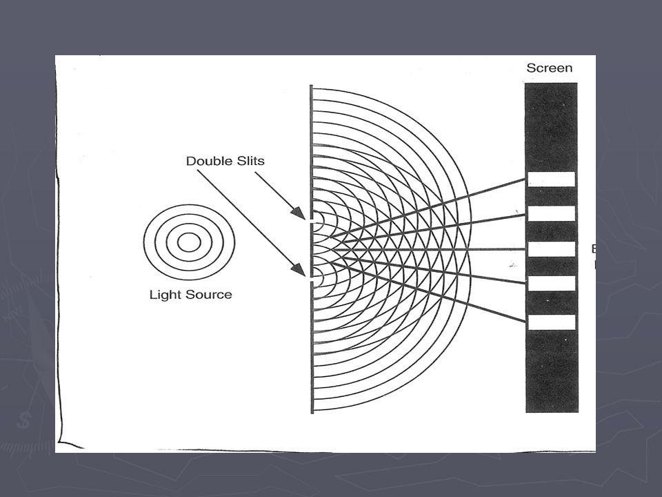
A. Diffraction- Bending of waves around a boundary. Readily seen with water waves. B. Young’s Double Slit experiment 1. Young showed that light bends or diffracts around boundaries. 1. Young showed that light bends or diffracts around boundaries. 2. Light was allowed to fall on two closely spaced narrow slits. 2. Light was allowed to fall on two closely spaced narrow slits. 3. The light passing through each slit was diffracted. 3. The light passing through each slit was diffracted. 4. The spreading light from the two slits overlap. (Interfere) 4. The spreading light from the two slits overlap. (Interfere)
 4. The spreading light from the two slits overlap. (Interfere).")
24
5. When the light from the two slits fell on a screen a pattern of light and dark bands were observed. Called interference fringes. 6.Bright bands correspond to constructive interference. (two crests or two troughs) 6.Bright bands correspond to constructive interference. (two crests or two troughs) 7. Dark bands correspond to destructive interference. (a crest and a trough) 8. Central Band- zero order band 9. bright bands on either side of the central band are referred to as the first order band, second- order band and so on.
 6.Bright bands correspond to constructive interference. (two crests or two troughs) 7. Dark bands correspond to destructive interference. (a crest and a trough) 8. Central Band- zero order band 9. bright bands on either side of the central band are referred to as the first order band, second- order band and so on..")
26
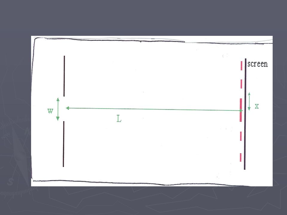
► J. Mathematical Relationship X = λL X = λL d Where X is the distance between any two bright bands.λ = wavelength of light used L= distance from the slits to the screen. d.= distance between the slits. Units of length all must be the same

27
1. Example Monochromatic light is incident on a pair of slits 1.95 X 10 -5 m apart. The distance between the first two bright bands is 2.11 X 10 -2 m. If the distance between the slits and the screen is 0.600m. A) calculate the wavelength A) calculate the wavelength B) state the color of the light B) state the color of the light d= 1.95 X 10 -5 m X= 2.11 X 10 -2 m L = 0.600m
 calculate the wavelength A) calculate the wavelength B) state the color of the light B) state the color of the light d= 1.95 X m X= 2.11 X m L = 0.600m.")
28
X = λL X = λL d 2.11 X 10 -2 m = λ( 0.600m) 1.95 X 10 -5 m 1.95 X 10 -5 m λ = 2.11 X 10 -2 m (1.95 X 10 -5 m) 0.6 00m 0.6 00m λ = 6.86 X 10 -7 m This is red light
 1.95 X m 1.95 X m λ = 2.11 X m (1.95 X m) m m λ = 6.86 X m This is red light")
29
III. Single Slit Diffraction A. Diffraction pattern produced differs from that of a double slit. A. Diffraction pattern produced differs from that of a double slit. 1. The central bright band is much wider than any of the other bright bands 1. The central bright band is much wider than any of the other bright bands 2. The intensity of the central band is greater than the intensity of any of the other bright bands. 2. The intensity of the central band is greater than the intensity of any of the other bright bands.

31
3. Mathematical Relationship 3. Mathematical Relationship X= λL X= λL wWhere X = separation distance between central band and dark band.λ = wavelength of light used L = distance from the slit to the screen. W = width of the slit. Units of length all must be the same

32
4. Example: Monochromatic orange light of wavelength 605nm falls on a single slit of width 0.095mm. The silt is located 85cm from a screen. How far is the first dark band? λ= 605nm = 605 X 10 -9 m w = 0.095mm =.000095m L = 85cm=.85m

33
X= λL w X=605 X 10 -9 m (.85m).000095m.000095m X =.0054m= 5.4mm
 m m X =.0054m= 5.4mm")
34
IV. Diffraction Gratings A. Used in practice to measure the wavelength of light. A. Used in practice to measure the wavelength of light. B. Made by scratching very fine lines with a diamond point on glass. B. Made by scratching very fine lines with a diamond point on glass. 1. The clear lines on the glass serve as the slits. 1. The clear lines on the glass serve as the slits. 2. There may be as many as 10,000 lines per cm. 2. There may be as many as 10,000 lines per cm. C. Interference Pattern similar to double silt except: C. Interference Pattern similar to double silt except:

35
1. The bright bands are narrower and the dark bands are broader. 1. The bright bands are narrower and the dark bands are broader. 2. gives a more precise measurement than double slit. 2. gives a more precise measurement than double slit. D. Mathematical relationship X = λL d

36
Examples: Examples: A good diffraction grating has 2.50 X 10 3 lines/cm. What is the distance between two lines in the grating? 1/2.50 X 10 3 lines/cm=.00040cm Example: Using a grating with a spacing of 4.00 X 10 -4 cm, a red line appears 16.5 cm from the central line on a screen. The screen is 1.00m from the grating. What is the wavelength of the red light.

37
X = λL d 16.5cm = λ(100cm) 4.00 X 10 -4 cm 4.00 X 10 -4 cm λ=6.6 X 10 -5 cm
 4.00 X cm 4.00 X cm λ=6.6 X cm")
Similar presentations