Download presentation
Presentation is loading. Please wait.

1
บทที่ 5 การกรอง (Filtration)
เรียบเรียงโดย อ.อรอุมา วงศางาม

2
การกรองเป็นการแยกทางกลอีกชนิดหนึ่ง
โดยของเหลวมีอนุภาคแขวนลอยอยู่ผ่านตัวกลางที่เป็นรูพรุน ตัวกลางจะจับอนุภาคที่แขวนลอย ซึ่งมีอนุภาคซึ่งมีขนาดใหญ่กว่าช่องเปิดของตัวกลาง แล้วให้ของเหลวซึ่งได้รับแรงให้เคลื่อนที่ผ่านไปได้

3
Filter cake = อนุภาคของแข็งซึ่งมีขนาดใหญ่กว่าช่องเปิดจะถูกกักอยู่บนผิวของตัวกรอง
Filtrate = ของเหลวซึ่งได้รับแรงให้เคลื่อนที่ผ่านตัวกรองไปได้ Filtering medium หรือ Septum = ตัวกรอง มีลักษณะเป็นรูพรุน

4
ทฤษฎีการวิเคราะห์การกรอง
The analysis of filtration is largely a question of studying the flow system. The fluid passes through the filter medium, which offers resistance to its passage, under the influence of a force which is the pressure differential across the filter. Thus, we can write the familiar equation: rate of filtration = driving force/resistance

5
Thus the overall equation giving the volumetric rate of flow dV/dt is:
As the total resistance is proportional to the viscosity of the fluid, we can write:

6
where R is the resistance to flow through the filte is the viscosity of the fluid r is the specific resistance of the filter cake Lc is the thickness of the filter cake L is the fictitious equivalent thickness of the filter cloth and pre-coat A is the filter area is the pressure drop across the filter.

7
If the rate of flow of the liquid and its solid content are known and assuming that all solids are retained on the filter, the thickness of the filter cake can be expressed by: Lc = wV/A where w is the fractional solid content per unit volume of liquid, V is the volume of fluid that has passed through the filter and A is the area of filter surface on which the cake forms. The resistance can then be written

8
and the equation for flow through the filter, under the driving force of the pressure drop is then:
Equation may be regarded as the fundamental equation for filtration. It expresses the rate of filtration in terms of quantities that can be measured, found from tables, or in some cases estimated. It can be used to predict the performance of large-scale filters on the basis of laboratory or pilot scale tests. Two applications of eqn. are filtration at a constant flow rate and filtration under constant pressure.

9
Constant-rate Filtration
In the early stages of a filtration cycle, it frequently happens that the filter resistance is large relative to the resistance of the filter cake because the cake is thin. Under these circumstances, the resistance offered to the flow is virtually constant and so filtration proceeds at a more or less constant rate.

10
Equation (10.12) can then be integrated to give the quantity of liquid passed through the filter in a given time. The terms on the right-hand side of eqn.(10.12) are constant so that integration is very simple: From eqn. (10.13) the pressure drop required for any desired flow rate can be found. Also, if a series of runs is carried out under different pressures, the results can be used to determine the resistance of the filter cake.
 the pressure drop required for any desired flow rate can be found. Also, if a series of runs is carried out under different pressures, the results can be used to determine the resistance of the filter cake.")
11
Constant-pressure Filtration
Once the initial cake has been built up, and this is true of the greater part of many practical filtration operations, flow occurs under a constant-pressure differential. Under these conditions, the term DP in eqn. (10.12) is constant and so and integration from V = 0 at t = 0, to V = V at t = t
 is constant and so. and integration from V = 0 at t = 0, to V = V at t = t.")
12
and rewriting this Y Slope X Intercept สมการเส้นตรง y= mx+c

13
Equation (10.14) is useful because it covers a situation that is frequently found in a practical filtration plant. It can be used to predict the performance of filtration plant on the basis of experimental results. If a test is carried out using constant pressure, collecting and measuring the filtrate at measured time intervals, a filtration graph can be plotted of t/(V/A) against (V/A) and from the statement of eqn. (10.14) it can be seen that this graph should be a straight line.
 against (V/A) and from the statement of eqn. (10.14) it can be seen that this graph should be a straight line.")
14
Slope = the intercept = Since, in general, , w, and A are known or can be measured, the values of the slope and intercept on this graph enable L and r to be calculated.

15
EX 1 Volume of filtrate from a filter press
A filtration test was carried out, with a particular product slurry, on a laboratory filter press under a constant pressure of 340 kPa and volumes of filtrate were collected as follows: The area of the laboratory filter was m2. In a plant scale filter, it is desired to filter a slurry containing the same material, but at 50% greater concentration than that used for the test, and under a pressure of 270 kPa. Estimate the quantity of filtrate that would pass through in 1 hour if the area of the filter is 9.3 m 2. Filtrate volume (kg) 20 40 60 80 Time (min) 8 26 54.5 93
 Time (min)")
16
From the experimental data:
V (kg) 20 40 60 80 t (s) 480 1560 3270 5580 V/A (kg/m2) 107.5 215 323 430 t/(V/A) (s m2 kg-1) 4.47 7.26 10.12 12.98
 t (s) V/A (kg/m2) t/(V/A) (s m2 kg-1)")
17
slope = the intercept =1.6 Fig 1 Filtration Graph

18
From the graph, we find that
These values of t/(V/A) are plotted against the corresponding values of V/A in Fig 1 From the graph, we find that the slope of the line is the intercept 1.6
 are plotted against the corresponding values of V/A in Fig 1. From the graph, we find that. the slope of the line is the intercept 1.6.")
19
Then substituting in eqn. (10.14) we have t/(V/A) = 0.0265(V/A) + 1.6.
To fit the desired conditions for the plant filter, the constants in this equation will have to be modified. If all of the factors in eqn. (10.14) except those which are varied in the problem are combined into constants, K and K', we can write (a)
 except those which are varied in the problem are combined into constants, K and K , we can write. (a)")
20
In the laboratory experiment ;
w=w1 and so that and For the new plant condition, w = w2 and P = P2 , so that, substituting in the eqn.(a) above, we then have for the plant filter, under the given conditions:
 above, we then have for the plant filter, under the given conditions:")
21
and since from these conditions
= 340/270 and w2/w1 = 150/100, t/(V/A) = (340/270)(150/100)(V/A) + 1.6(340/270) = 0.05(V/A) t = 0.5(V/A) (V/A).
 = (340/270)(150/100)(V/A) + 1.6(340/270) = 0.05(V/A) t = 0.5(V/A) (V/A).")
22
To find the volume that passes the filter in 1 h which is 3600 s, that is to find V for t = 3600.
= 0.05(V/A) (V/A) and solving this quadratic equation, we find that V/A = 250 kg/ m2 and so the slurry passing through 9.3 m2 in 1 h would be= 250 x 9.3 = 2325 kg.
 (V/A) and solving this quadratic equation, we find that V/A = 250 kg/ m2. and so the slurry passing through 9.3 m2 in 1 h would be= 250 x 9.3 = 2325 kg.")
23
Filtration Equipment The basic requirements for filtration equipment are: mechanical support for the filter medium flow accesses to and from the filter medium provision for removing excess filter cake In some instances, washing of the filter cake to remove traces of the solution may be necessary. Pressure can be provided on the upstream side of the filter, or a vacuum can be drawn downstream, or both can be used to drive the wash fluid through.

24
Filtration Equipment Plate and frame filter press Rotary vacuum filter
Centrifugal filter

25
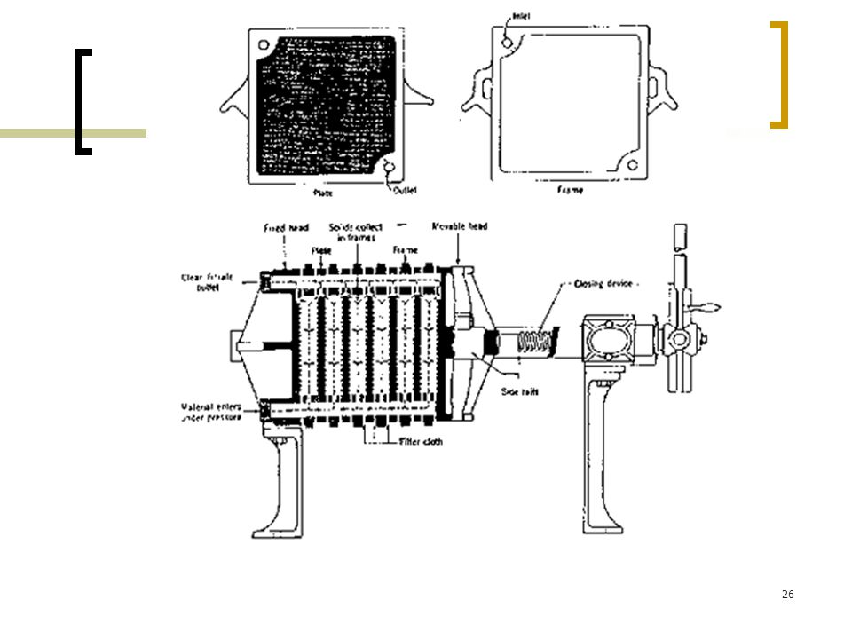
1. Plate and frame filter press
Fig 2 Plate and frame filter press

27
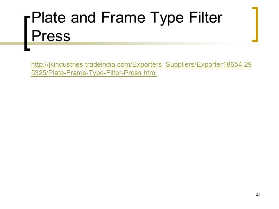
Plate and Frame Type Filter Press
28
In the plate and frame filter press, a cloth or mesh is spread out over plates which support the cloth along ridges but at the same time leave a free area, as large as possible, below the cloth for flow of the filtrate. The plates with their filter cloths may be horizontal, but they are more usually hung vertically with a number of plates operated in parallel to give sufficient area.

29
Filter cake builds up on the upstream side of the cloth, that is the side away from the plate.
In the early stages of the filtration cycle, the pressure drop across the cloth is small and filtration proceeds at more or less a constant rate. As the cake increases, the process becomes more and more a constant-pressure one and this is the case throughout most of the cycle.

30
When the available space between successive frames is filled with cake, the press has to be dismantled and the cake scraped off and cleaned, after which a further cycle can be initiated.

31
The plate and frame filter press is cheap but it is difficult to mechanize to any great extent.
Variants of the plate and frame press have been developed which allow easier discharging of the filter cake. For example, the plates, which may be rectangular or circular, are supported on a central hollow shaft for the filtrate and the whole assembly enclosed in a pressure tank containing the slurry. Filtration can be done under pressure or vacuum.

32
The advantage of vacuum filtration is that the pressure drop can be maintained whilst the cake is still under atmospheric pressure and so can be removed easily. The disadvantages are the greater costs of maintaining a given pressure drop by applying a vacuum and the limitation on the vacuum to about 80 kPa maximum. In pressure filtration, the pressure driving force is limited only by the economics of attaining the pressure and by the mechanical strength of the equipment.

33
2. Rotary filters Fig 3 Rotary filters

34
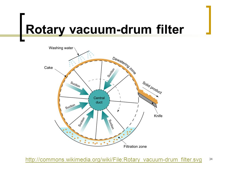
Rotary vacuum-drum filter
35
http://snair. tradeindia. com/Exporters_Suppliers/Exporter13280
36
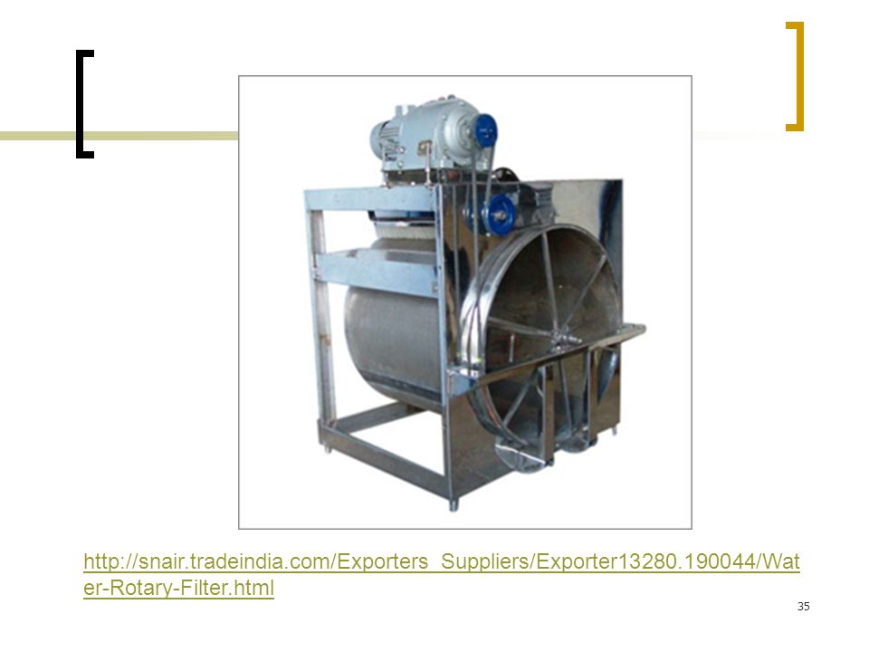
The Rotary Drum Filter Description
The Rotary Vacuum Drum Filter belongs to the bottom feed group and is one of the oldest filters applied to the chemical process industry. The filter consists of the following subassemblies:

37
Rotary filters In rotary filters, the flow passes through a rotating cylindrical cloth from which the filter cake can be continuously scraped. Either pressure or vacuum can provide the driving force, but a particularly useful form is the rotary vacuum filter. In this, the cloth is supported on the periphery of a horizontal cylindrical drum that dips into a bath of the slurry. Vacuum is drawn in those segments of the drum surface on which the cake is building up. A suitable bearing applies the vacuum at the stage where the actual filtration commences and breaks the vacuum at the stage where the cake is being scraped off after filtration. Filtrate is removed through trunnion bearings. Rotary vacuum filters are expensive, but they do provide a considerable degree of mechanization and convenience. A rotary vacuum filter is illustrated diagrammatically in Fig. 10.8(b).
.")
38
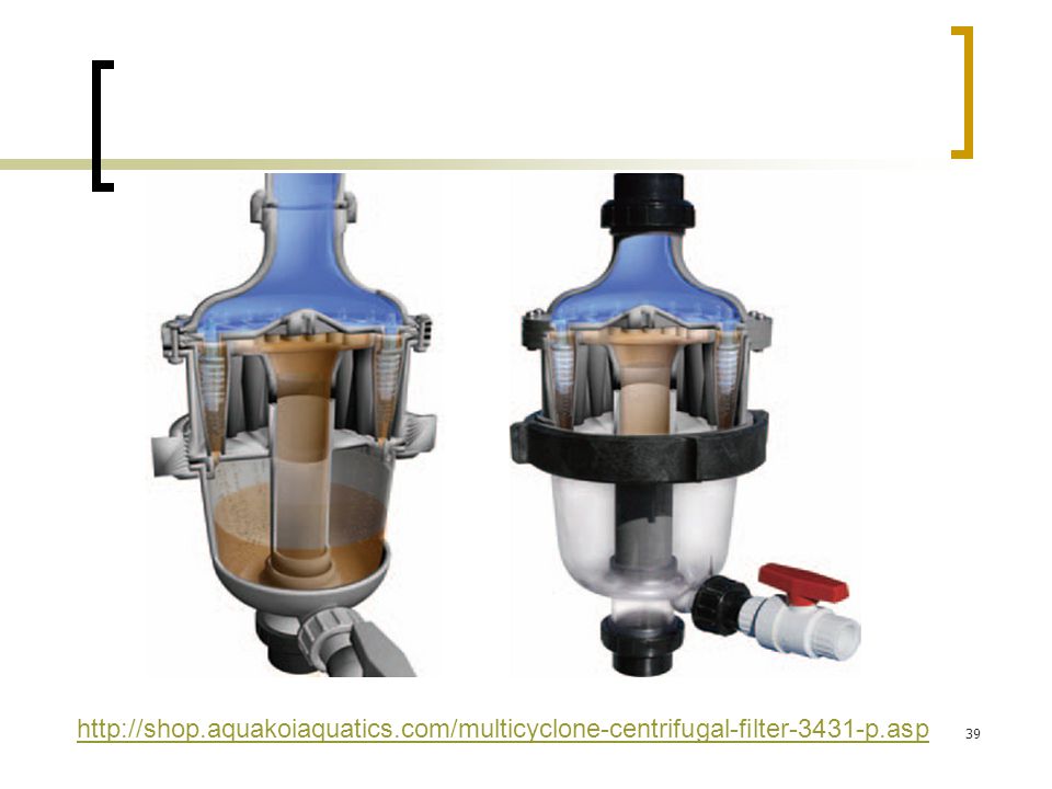
Centrifugal filters Fig 4 Centrifugal filters

39
http://shop. aquakoiaquatics
40
Centrifugal filters Centrifugal force is used to provide the driving force in some filters. These machines are really centrifuges fitted with a perforated bowl that may also have filter cloth on it. Liquid is fed into the interior of the bowl and under the centrifugal forces, it passes out through the filter material. This is illustrated in Fig. 10.8(c).
.")
41
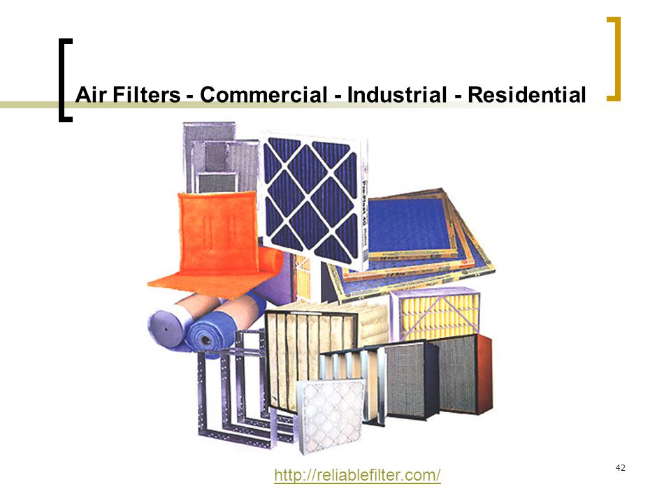
Air filters Filters are used quite extensively to remove suspended dust or particles from air streams. The air or gas moves through a fabric and the dust is left behind. These filters are particularly useful for the removal of fine particles. One type of bag filter consists of a number of vertical cylindrical cloth bags cm in diameter, the air passing through the bags in parallel. Air bearing the dust enters the bags, usually at the bottom and the air passes out through the cloth.

42
Air Filters - Commercial - Industrial - Residential
43
A familiar example of a bag filter for dust is to be found in the domestic vacuum cleaner. Some designs of bag filters provide for the mechanical removal of the accumulated dust. For removal of particles less than 5 mm diameter in modern air sterilization units, paper filters and packed tubular filters are used. These cover the range of sizes of bacterial cells and spores.

Similar presentations


>")


 for control of airborne contaminants.>")


