Download presentation
Presentation is loading. Please wait.

1
Design of a Transverse Field Magneto-Optical Filter Consortium for Undergraduate Research Experience (CURE) Rossen Chemelekov, Los Angeles City College Kelvin Konevsky, Los Angeles Valley College Mentor: Dr. Neil Murphy, Jet Propulsion Laboratory

2
Introduction Objective: Development and testing of a transverse field Magneto-Optical Filter (MOF) to improve the Compact Doppler/Magnetograph (CDM) Benefits: The CDM is smaller and lighter than current Doppler and Magnetoraph instruments that are used in space. The transverse field MOF should provide an improvement in the sensitivity of the CDM.

3
What Does a Doppler/Magnetograph Do? The Compact Doppler/Magnetograph is designed to be a low-cost flight instrument that images the full solar disk through two narrow-band filters at the red and blue wings of the solar potassium absorption line. It measures the line-of-sigh velocity and magnetic field of the Sun's photosphere.

4
Why study the sun? The Sun is a star: studying it helps us learn about other stars Space Weather affects us It's a Physical Laboratory – fusion The CDM is used to perform seismology of the Sun – sounding its interior to determine its structure. Magnetic field measurements show us how active magnetic regions and sunsports evolve

5
Data Collection We use a Heliostat to track the sun and provide light to the Compact Doppler/Magnetograph.

6
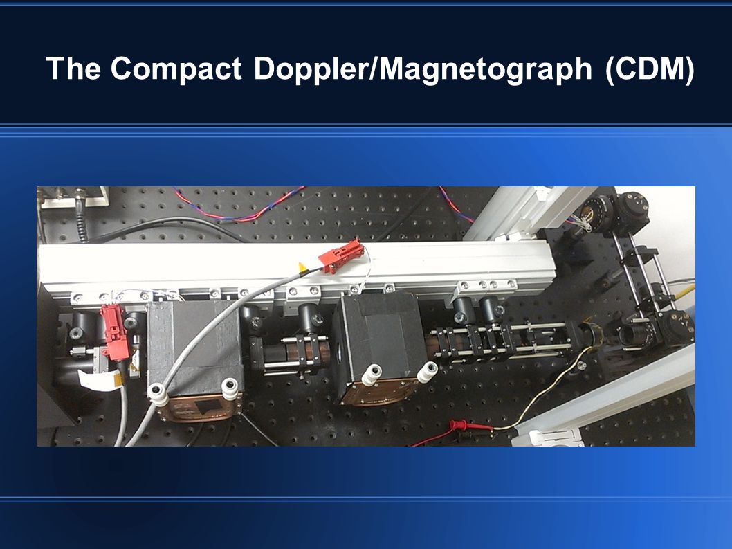
The Compact Doppler/Magnetograph (CDM)
")
8
Compact Doppler/Magnetograph Overview Fig.1 (above) shows a schematic diagram of the Magneto-Optical Filter The CDM has three parts: Polarization analyzer Filter Section Zeeman Effect Birefringence Wing Selector Inverse Zeeman Effect
 shows a schematic diagram of the Magneto-Optical Filter The CDM has three parts: Polarization analyzer Filter Section Zeeman Effect Birefringence Wing Selector Inverse Zeeman Effect")
9
MOF pass-bands Pass-bands after filter section Single pass-band after wing selector Longitudinal field caseTransverse field at 45° case In the transverse field case, the final pass-band is narrower, allowing better velocity sensitivity (less smoothing of the solar line) Zeeman split line positions
 Zeeman split line positions")
10
Existing Magnet Assembly

11
New Magnet

12
Designing the Transverse Field MOF

13
The New MOF

14
It Works!

15
Initial Sensitivity Measurements Fig. 3 Shows initial sensitivity measurements of the transverse field MOF based on data collected over several days of testing.

16
Future Measurements In the future further testing should be performed with direct comparison between the sensitivity of the two MOF. There's a light leak-through, probably due to contamination on the cell windows, which needs to be addressed in order to increase the intensity and sensitivity of the image.

17
Acknowledgment We would like to thank our mentor Dr. Neil Murphy, CURE program director Paul McCudden, as well as Rich Alvidrez, Marshal Fong, Dr. Milan Mijic and last but not least our fellow interns Tzitlaly Barajas and Karen Garcia. This research was supported by the National Science Foundation under grant 0852088 to Cal State LA, it was carried out at NASA's Jet Propulsion Laboratory.

18
Questions? Video (above) shows a time-lapse clip of the Sun as observed on July 11th, 2012
 shows a time-lapse clip of the Sun as observed on July 11th, 2012")
Similar presentations
 – National Center for Atmospheric Research (NCAR) The National Center for Atmospheric Research is operated by the University.>")

, A. Winebarger², S. Farid³,>")
. temperature (compare to blackbody curve). (line-of-sight) velocity.>")


 evolution and solar rotation well define long term, persistent, coronal streamers.>")


