Download presentation
Presentation is loading. Please wait.

1
Electrical Seminar Your Voltmeter is the best tool to have in your tool box! Presented by Larry Shepard Missouri Valley Region MARC

2
Here’s a comment or two I’d like to share with you from a few things I read while preparing for the seminar. -How do you expect me to trouble shoot the car with the meter when I don’t even know what to do on the meter? -One fellow wrote: I don’t understand but with all things electrical no two people will give you the same answer. The bigger mystery is deciding which answers are correct. It is a black art. Not everyone can understand. I’ll die never understanding… signed Bob

3
AnalogDigital

4
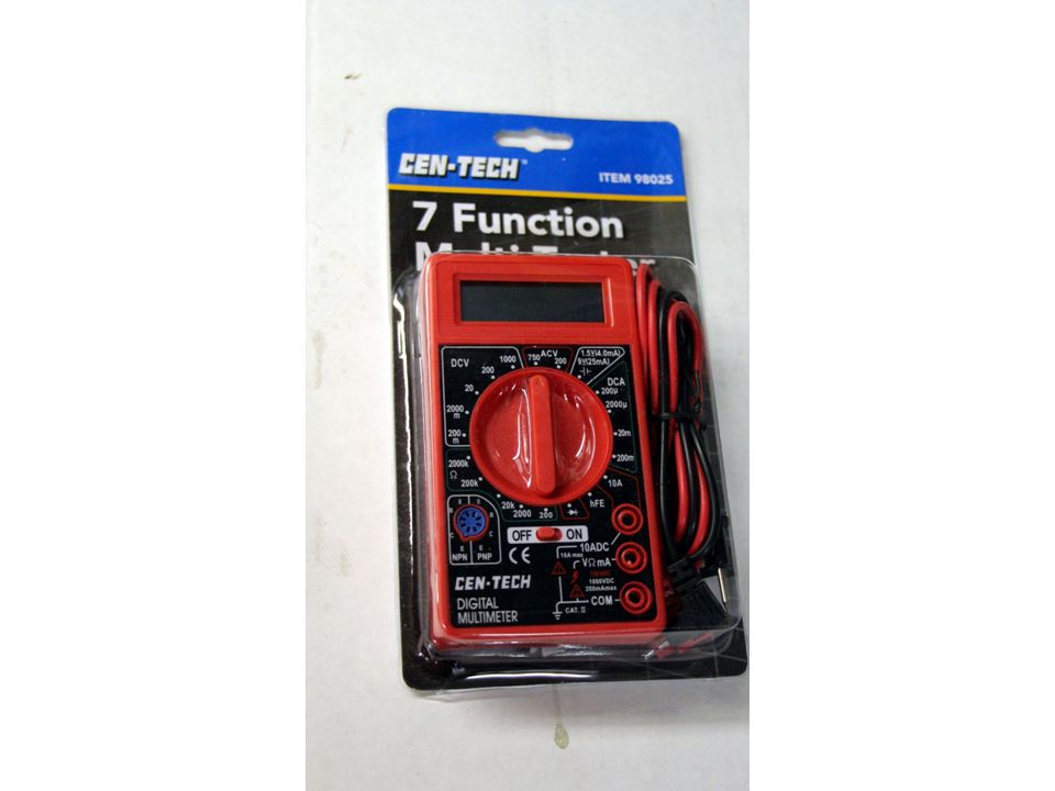
Volt/Ohm Meters.The older meters were called “analog” for their needle/reflective type nature. Today’s newer meters are “digital” in nature and much simpler to use and understand. There are cheap inexpensive meters that will do the job for roadside or an occasional garage function use. These typically have their own on/off switch ( don’t forget to turn it off when done) and have a setting that you must “set the meter to “ for correct useage, like 20V (volt) scale DC for most automotive applications of 6 or 12Volt. More expensive meters, like Fluke brank often have autorange feautures where you don’t have to worry about selecting the range to test the circuit. If you don’t mind spending a little more a better meter is well worth it. Also.. carry an extra set of batteries for your meter if you’re carrying it with you in the “A”. Nothing worse than a car that’s dead and your meter.
 and have a setting that you must set the meter to for correct useage, like 20V (volt) scale DC for most automotive applications of 6 or 12Volt. More expensive meters, like Fluke brank often have autorange feautures where you don’t have to worry about selecting the range to test the circuit. If you don’t mind spending a little more a better meter is well worth it. Also.. carry an extra set of batteries for your meter if you’re carrying it with you in the A . Nothing worse than a car that’s dead and your meter..")
5
Examples of Digital Meters Harbor Freight Fluke

7
Example of “Clamp On” style meter for measuring current without breaking circuit

8
Test Leads

9
Needless to say...hopefully we will be of some help to you today. The electrical system in an “A” is pretty basic, but can still be challenging… so to better understand things… let’s start with some basic principles first.

10
Voltage( Measured in Volts) – the electrical “pressure” that is provided in the circuit by the battery ( or other power source). The Model A is a 6 volt electrical system, a 12 volt system would have of course more “pressure” or voltage. Current ( Measured in Amps, short for Amperage) – is the rate of flow of the electricity (electrons) You can correlate it to like the flow of a river. A larger fast flowing river has more power than a small stream. Resistance ( load)– Wire in itself can be a load on a circuit. A light bulb, coil, radio, etc are all loads in a 6 or 12 volt automotive system. Additionally, poor connections, loose, dirty, etc can also cause additional load which can cause poor function within the circuit.
 – is the rate of flow of the electricity (electrons) You can correlate it to like the flow of a river. A larger fast flowing river has more power than a small stream. Resistance ( load)– Wire in itself can be a load on a circuit. A light bulb, coil, radio, etc are all loads in a 6 or 12 volt automotive system. Additionally, poor connections, loose, dirty, etc can also cause additional load which can cause poor function within the circuit..")
11
Shorts/Opens An “open” is a break in the circuit, meaning that there is a poor connection/break in the wire, or something in the circuit that is preventing the voltage to be present. A “short” is where the hot lead is in connection improperly to the ground or other source or hot wire. When this occurs the common reference is “shorted”. This can be due to connection issues, bare wires/burned/melted together wires, bad switches. Etc. The volt-ohm meter can be used to effectively and quickly pinpoint the source of these. With a few basic checks you can pinpoint where the problems exist and correct them.

13
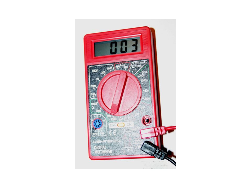
Measure DC voltage

14
Meter Set to Ohms To measure resistance

15
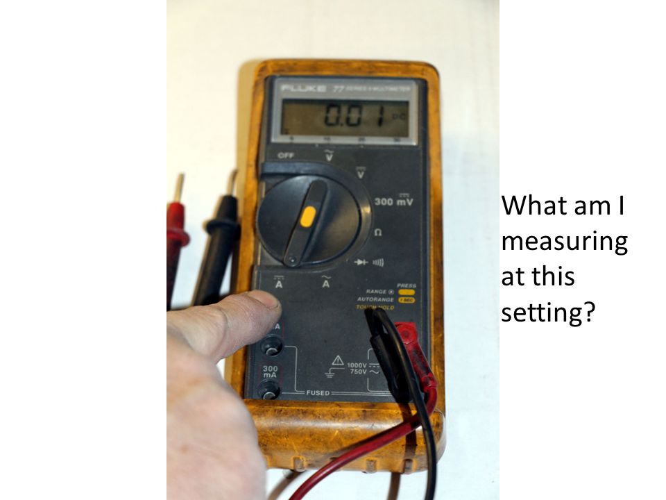
Measure DC Current (Amps)
")
16
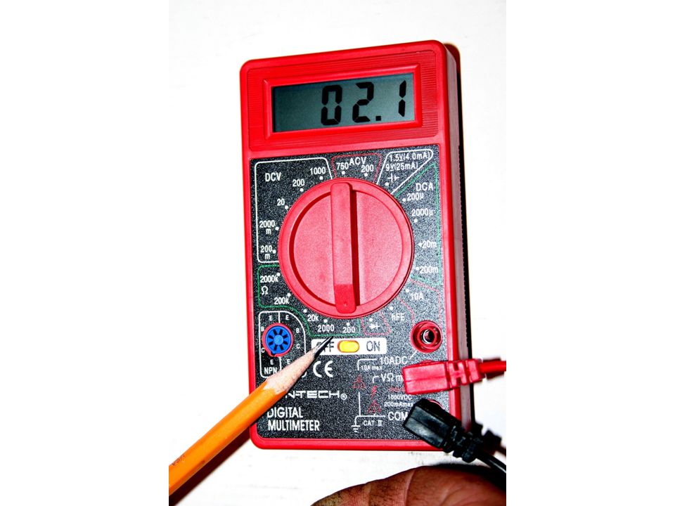
What am I measuring at this setting?

22
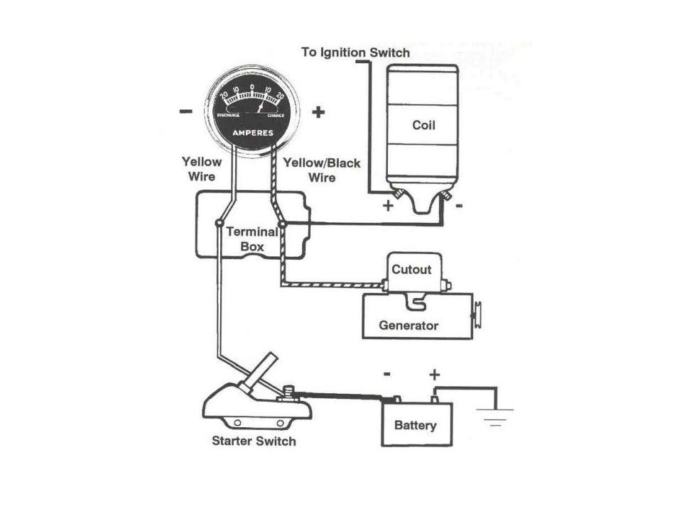
Voltage check at starter switch Remember your battery polarity, Positive ground ( red lead is positive on meter) black is negative
 black is negative")
23
Voltage check at Terminal Box Both lugs should be the same voltage. If not then you have a poor connection at the terminal box or the ammeter

24
Voltage check at coil (both terminals)
")
26
A few Resistance checks….. Coil 1.2-1.4 ohms at the Primary terminals Primary is low voltage, secondary is High voltage. - An original straight pole coil produces approximatetly 10-12 Kvolts (10,000- 12,000 volts) -An original slant pole coil will produce approximately 14-18KV (14,000-18,000) -Cutout exciter coil between ground and armature terminal is approximately 48 ohms – should show open between the terminals when no input voltage/current is applied. If shorted then internal problem with cutout exist.
 -An original slant pole coil will produce approximately 14-18KV (14,000-18,000) -Cutout exciter coil between ground and armature terminal is approximately 48 ohms – should show open between the terminals when no input voltage/current is applied. If shorted then internal problem with cutout exist..")
27
Coil Polarity Checker Courtesty of Brattons

28
Coil output tester, adjust pin down to check for large KV output Tester courtesy of Brattons

29
High Quality Harness Harness made/supplied by Bratton’s

30
Soldered Connections

31
NOS Cutout – ( yes I know it’s a closed foot)
")
32
Measure resistance of exciter coil in cutout It should be approx 48 Ohms

33
Looking for opens/low voltage. -Check from the battery source on top of the starter switch. This is a common problem area on the “A”’s. -Make sure the nut is tight holding the batter cable down. Measure the voltage at the connection, then move to the battery lead on the generator cutout, and then terminal box ( both terminals), coil ( both sides). Voltage should be within a tenth of a volt with engine not running. If it is less you have a poor connection somewhere. Most likely the terminal box.
, coil ( both sides). Voltage should be within a tenth of a volt with engine not running. If it is less you have a poor connection somewhere. Most likely the terminal box..")
34
A few potential problem areas ( battery/ignition circuit) : -Ring terminal and wire poor at starter switch -Fuse mounts – if present in poor shape, terminals not tight or clean -poor wiring/terminal at generator -poor connections at terminal box. Must be clean and tight -Repro terminal boxes troublesome – Need fixed prior to installation on the firewall -Popout/ignition switch connection not tight or popout switch has internal connection problem or wiring inner cable to distributor

35
-Ammeter connections not tight – must be brass ammeter No aluminum backed ammeters -Possible shorting of screw in contact from ignition cable to distributor. Tip in insulating – when rebuilding distributor use a rubber insualtor between lower plate and housing. It will never short, no matter how much you screw it in! -Poor pigtail at distributor upper to lower plate ( very common) -Poor point alignment
 -Poor point alignment.")
36
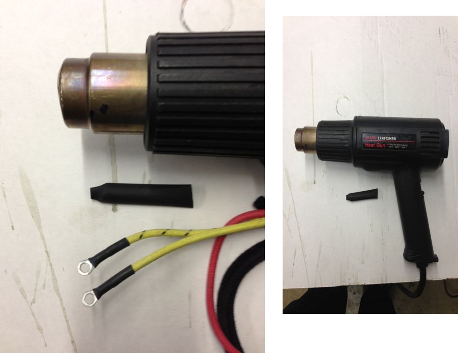
Good wiring practice tips: 1. Use good quality terminals – solder if at all possible 2. Use heatshrink on terminal ends 3. If a splice/repair is necessary solder the connection and use heatshrink – not a junk crimp splice 4. Use high quality wiring – Brattons harnesses recommended, sometimes you have to relieve the wiring loom with a razor blade on the dash harness at the dash 5. Use correct wiring clips and bullet ends. Make sure all connectors on headlight wiring are soldered at the connector. Then insert into bullet splice and ensure tight. Neatness counts! Use wire tires where necessary if on a driver. Bullet connectors inside of the headlights are good idea and helps to eliminate troublesome connections at ferrules /headlight 6- Use your meter and check for good grounds.

37
7. Repro terminal boxes need the studs tightened and back screws epoxy filled prior to mounting if used. Check all boxes for tight studs. 8. Ensure good clean battery cables and routing. Be aware of chaffing potential 9. Use the correct gauge wire for the voltage/circuit/load.

39
Can’t fix your popout/ignition switch… this keeps it simple.

40
Security by Coco

Similar presentations


>")


