Download presentation
Presentation is loading. Please wait.

1
555 timer

2
555 timer; - What is the 555 timer?
Pin configurations of the 555 timer ; 555 timer in astable operation ; 555 timer in monostable operation ; What are the 555 timer applications?

3
555 Timer; The 555 timer is one of the most remarkable integrated circuits ever developed. It comes in a single or dual package and even low power cmos versions exist - ICM7555. Common part numbers are; LM555, NE555, LM556, NE556.

4
Pin configurations

5
two voltage comparators a bi-stable flip flop a discharge transistor
The 555 timer consists of; two voltage comparators a bi-stable flip flop a discharge transistor and a resistor divider network.

7
555 timer in astable operation ;

8
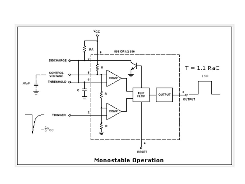
555 timer in monostable operation ;

9
Applications using 555 timer;
- Random Flashers ; - A light dimmer ; ; - A car tachometer - Traffic Lights ; - Infra Red (IR) remote control ;
 remote control ;")
10
'Random' Flasher for 8 LEDs Project

12
What is a light dimmer?

13
A light dimmer is a means of controlling the
"brightness" level of a lamp

15
For the light dimmer to work the 555 timer is configured as a "variable cycle", astable oscillator running some where around 300 Hz.

16
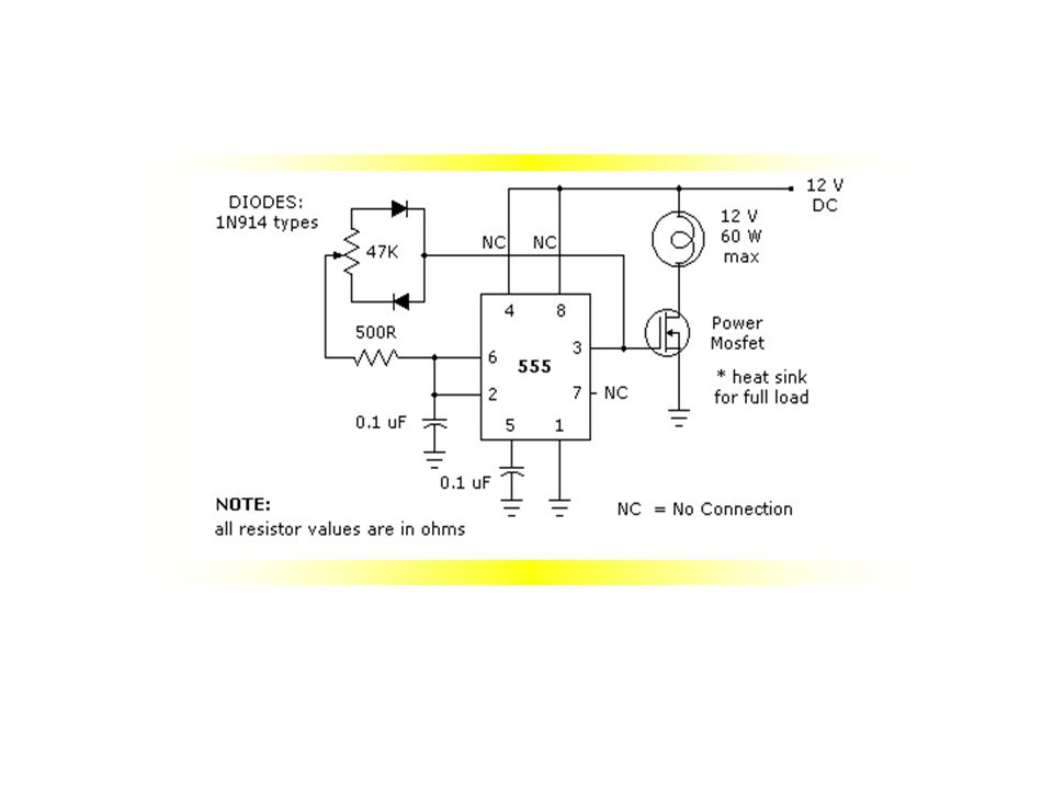
What is a car tachometer?

17
A tachometer is simply a means of counting the engine revolutions of an automobile engine.

18
In this suggested idea a NE555 timer is configured as a monostable or one shot.
The period of the 555 timer for our car tachometer is determined by the resistor from the 9V regulated supply to pin 7 (50K) and the capacitor from pin 6 and ground (0.1 uF). Time "T" = 1.1 RC or 1.1 X 50,000 X 0.1 X10 -6 = or 5.5 mS (milli-seconds).
 and the capacitor from pin 6 and ground (0.1 uF). Time T = 1.1 RC or 1.1 X 50,000 X 0.1 X10 -6 = or 5.5 mS (milli-seconds).")
20
Extra: Supply is taken from the 12V automobile system and for the NE555 timer car tachometer is reduced to a regulated 9V by the 15 ohm resistor in conjunction with the 9V zener diode. Note that the 10 uF polarised capacitor must be placed physically as close as possible to the supply pin 8. It is depicted in the schematic diagram in this manner purely for clarity.

21
Traffic Light

23
The time taken for the complete red - red & amber - green – amber
sequence can be varied from about 7s to about 2½minutes by adjusting the 1M preset.

24
IR Remote Control

25
We know that if we want to calculate charging, discharging
time and the frequency, we will use these equs.

27
Questions

28
If you ask or even try

30
adel al khamees

Similar presentations


. What is a Counter? In digital logic and computing, a counter is a device which stores (and sometimes displays)>")
>")


