Download presentation
Presentation is loading. Please wait.

1
Chapter 8 – Principles of Solidification
The Science and Engineering of Materials, 4th ed Donald R. Askeland – Pradeep P. Phulé Chapter 8 – Principles of Solidification

2
Objectives of Chapter 8 Study the principles of solidification as they apply to pure metals. Examine the mechanisms by which solidification occurs. Examine how techniques such as welding, brazing, and soldering are used for joining metals.

3
Chapter Outline 8.1 Technological Significance 8.2 Nucleation
8.3 Applications of Controlled Nucleation 8.4 Growth Mechanisms 8.5 Solidification Time and Dendrite Size 8.6 Cooling Curves 8.7 Cast Structure 8.8 Solidification Defects

4
Chapter Outline (Continued)
8.9 Casting Processes for Manufacturing Components 8.10 Continuous Casting and Ingot Casting 8.11 Directional Solidification (DS), Single Crystal Growth, and Epitaxial Growth 8.12 Solidification of Polymers and Inorganic Glasses 8.13 Joining of Metallic Materials
, Single Crystal Growth, and Epitaxial Growth Solidification of Polymers and Inorganic Glasses Joining of Metallic Materials.")
5
Section 8.1 Technological Significance
Primary processing - Processes involving casting of molten metals into ingots or semi-finished useful shapes such as slabs. Secondary processing - Processes such as rolling, extrusion, etc.used to process ingots or slabs and other semi-finished shapes.

6
Figure 8. 1 An image of a bronze object
Figure 8.1 An image of a bronze object. This Canteen (bian hu) from China, Warring States period, circa 3rd century BCE (bronze inlaid with silver). (Courtesy of Freer Gallery of Art, Smithsonian Institution, Washington, D.C.) Figure 8.2 (a) Aluminum alloy wheels for automotives, (b) optical fibers for communication. (Courtesy of PhotoDisc/Getty Images.)
 from China, Warring States period, circa 3rd century BCE (bronze inlaid with silver). (Courtesy of Freer Gallery of Art, Smithsonian Institution, Washington, D.C.) Figure 8.2 (a) Aluminum alloy wheels for automotives, (b) optical fibers for communication. (Courtesy of PhotoDisc/Getty Images.)")
7
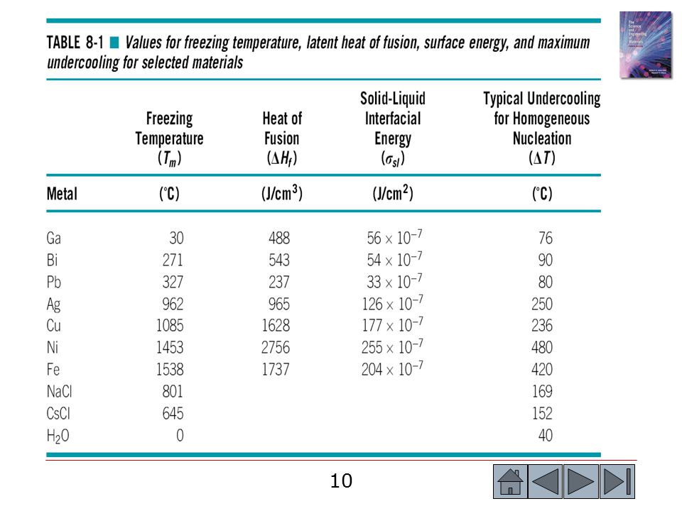
Section 8.2 Nucleation Nucleation - The physical process by which a new phase is produced in a material. Critical radius (r*) - The minimum size that must be formed by atoms clustering together in the liquid before the solid particle is stable and begins to grow. Undercooling - The temperature to which the liquid metal must cool below the equilibrium freezing temperature before nucleation occurs. Homogeneous nucleation - Formation of a critically sized solid from the liquid by the clustering together of a large number of atoms at a high undercooling (without an external interface). Heterogeneous nucleation - Formation of a critically sized solid from the liquid on an impurity surface.
 - The minimum size that must be formed by atoms clustering together in the liquid before the solid particle is stable and begins to grow. Undercooling - The temperature to which the liquid metal must cool below the equilibrium freezing temperature before nucleation occurs. Homogeneous nucleation - Formation of a critically sized solid from the liquid by the clustering together of a large number of atoms at a high undercooling (without an external interface). Heterogeneous nucleation - Formation of a critically sized solid from the liquid on an impurity surface.")
8
Figure 8.3 An interface is created when a solid forms from the liquid
©2003 Brooks/Cole, a division of Thomson Learning, Inc. Thomson Learning™ is a trademark used herein under license. Figure 8.3 An interface is created when a solid forms from the liquid

9
©2003 Brooks/Cole, a division of Thomson Learning, Inc
©2003 Brooks/Cole, a division of Thomson Learning, Inc. Thomson Learning™ is a trademark used herein under license. Figure 8.4 The total free energy of the solid-liquid system changes with the size of the solid. The solid is an embryo if its radius is less than the critical radius, and is a nucleus if its radius is greater than the critical radius

11
Example 8.1 Calculation of Critical Radius for the Solidification of Copper
Calculate the size of the critical radius and the number of atoms in the critical nucleus when solid copper forms by homogeneous nucleation. Comment on the size of the nucleus and assumptions we made while deriving the equation for radius of nucleus. Example 8.1 SOLUTION

12
Example 8.1 SOLUTION (Continued)
")
13
©2003 Brooks/Cole, a division of Thomson Learning, Inc
©2003 Brooks/Cole, a division of Thomson Learning, Inc. Thomson Learning™ is a trademark used herein under license. Figure 8.5 A solid forming on an impurity can assumed the critical radius with a smaller increase in the surface energy. Thus, heterogeneous nucleation can occur with relatively low undercoolings

14
©2003 Brooks/Cole, a division of Thomson Learning, Inc
©2003 Brooks/Cole, a division of Thomson Learning, Inc. Thomson Learning™ is a trademark used herein under license. Figure 8.6 Rate of nucleation (l) as a function of temperature of the liquid (T)
 as a function of temperature of the liquid (T)")
15
Section 8.3 Applications of Controlled Nucleation
Grain refinement - The addition of heterogeneous nuclei in a controlled manner to increase the number of grains in a casting. Dispersion strengthening - Increase in strength of a metallic material by generating resistance to dislocation motion by the introduction of small clusters of a second material. Solid-state phase transformation - A change in phase that occurs in the solid state. Rapid solidification processing - Producing unique material structures by promoting unusually high cooling rates during solidification.

16
Section 8.4 Growth Mechanisms
Specific heat - The heat required to change the temperature of a unit weight of the material one degree. Solidification front - Interface between a solid and liquid. Planar growth - The growth of a smooth solid-liquid interface during solidification, when no undercooling of the liquid is present. Dendrite - The treelike structure of the solid that grows when an undercooled liquid solidifies.

17
©2003 Brooks/Cole, a division of Thomson Learning, Inc
©2003 Brooks/Cole, a division of Thomson Learning, Inc. Thomson Learning™ is a trademark used herein under license. Figure 8.7 When the temperature of the liquid is above the freezing temperature a protuberance on the solid-liquid interface will not grow, leading to maintenance of a planer interface. Latent heat is removed from the interface through the solid

18
©2003 Brooks/Cole, a division of Thomson Learning, Inc
©2003 Brooks/Cole, a division of Thomson Learning, Inc. Thomson Learning™ is a trademark used herein under license. Figure 8.8 (a) If the liquid is undercooled, a protuberance on the solid-liquid interface can grow rapidly as a dendrite. The latent heat of fusion is removed by raising the temperature of the liquid back to the freezing temperature. (b) Scanning electron micrograph of dendrites in steel (x 15)
 If the liquid is undercooled, a protuberance on the solid-liquid interface can grow rapidly as a dendrite. The latent heat of fusion is removed by raising the temperature of the liquid back to the freezing temperature. (b) Scanning electron micrograph of dendrites in steel (x 15)")
19
Section 8.5 Solidification Time and Dendrite Size
Chvorinov’s rule - The solidification time of a casting is directly proportional to the square of the volume-to-surface area ratio of the casting. Mold constant (B) - A characteristic constant in Chvorinov’s rule. Secondary dendrite arm spacing (SDAS) - The distance between the centers of two adjacent secondary dendrite arms.
 - A characteristic constant in Chvorinov’s rule. Secondary dendrite arm spacing (SDAS) - The distance between the centers of two adjacent secondary dendrite arms.")
20
Example 8.2 Redesign of a Casting for Improved Strength
Your company currently is producing a disk-shaped brass casting 2 in. thick and 18 in.in diameter. You believe that by making the casting solidify 25% faster, the improvement in the tensile properties of the casting will permit the casting to be made lighter in weight. Design the casting to permit this.Assume that the mold constant is 22 min/in.2 for this process.

21
Example 8.2 SOLUTION If d is the diameter and x is the thickness of the casting, then the volume, surface area, and solidification time of the 2-in.thick casting are:

22
Example 8.2 SOLUTION (Continued)
Since the casting conditions have not changed, the mold constant B is unchanged. The V/A ratio of the new casting is:

23
Figure 8. 9 (a) The secondary dendrite arm spacing (SDAS)
Figure 8.9 (a) The secondary dendrite arm spacing (SDAS). (b) Dendrites in an aluminum alloy (x 50). (From ASM Handbook, Vol. 9, Metallography and Microstructure (1985), ASM International, Materials Park, OH )
 The secondary dendrite arm spacing (SDAS). (b) Dendrites in an aluminum alloy (x 50). (From ASM Handbook, Vol. 9, Metallography and Microstructure (1985), ASM International, Materials Park, OH )")
24
©2003 Brooks/Cole, a division of Thomson Learning, Inc
©2003 Brooks/Cole, a division of Thomson Learning, Inc. Thomson Learning™ is a trademark used herein under license. Figure The effect of solidification time on the secondary dendrite arm spacings of copper, zinc and aluminum

25
©2003 Brooks/Cole, a division of Thomson Learning, Inc
©2003 Brooks/Cole, a division of Thomson Learning, Inc. Thomson Learning™ is a trademark used herein under license. Figure The effect of the secondary dendrite arm spacing on the properties of an aluminum casting alloy

26
Example 8.3 Secondary Dendrite Arm Spacing for Aluminum Alloys
Determine the constants in the equation that describe the relationship between secondary dendrite arm spacing and solidification time for aluminum alloys (Figure 8.10). ©2003 Brooks/Cole, a division of Thomson Learning, Inc. Thomson Learning™ is a trademark used herein under license. Figure The effect of solidification time on the secondary dendrite arm spacings of copper, zinc and aluminum
. ©2003 Brooks/Cole, a division of Thomson Learning, Inc. Thomson Learning™ is a trademark used herein under license. Figure 8.10 The effect of solidification time on the secondary dendrite arm spacings of copper, zinc and aluminum.")
27
Example 8.3 SOLUTION Figure 8.10, we can mark five equal units on the vertical scale and 12 equal units on the horizontal scale.The slope is:

28
Example 8.4 Time of Solidification
A 4-in.-diameter aluminum bar solidifies to a depth of 0.5 in. beneath the surface in 5 minutes. After 20 minutes, the bar has solidified to a depth of 1.5 in. How much time is required for the bar to solidify completely? Example 8.4 SOLUTION From our measurements, we can determine the constants ksolidification and c1.

29
Example 8.5 Design of an Aluminum Alloy Casting
Design the thickness of an aluminum alloy casting whose length is 12 in. and width is 8 in., in order to produce a tensile strength of 40,000 psi. The mold constant in Chvorinov’s rule for aluminum alloys cast in a sand mold is 45 min/in2. Assume that data shown in Figures 8.10 and 8.11 can be used. ©2003 Brooks/Cole, a division of Thomson Learning, Inc. Thomson Learning™ is a trademark used herein under license. Figure The effect of solidification time on the secondary dendrite arm spacings of copper, zinc and aluminum

30
Example 8.5 (Continued) ©2003 Brooks/Cole, a division of Thomson Learning, Inc. Thomson Learning™ is a trademark used herein under license. Figure The effect of the secondary dendrite arm spacing on the properties of an aluminum casting alloy

31
Example 8.5 SOLUTION Since the length is 12 in.and the width is 8 in.: Thickness of an aluminum alloy casting

32
Section 8.6 Cooling Curves
Recalescence - The increase in temperature of an undercooled liquid metal as a result of the liberation of heat during nucleation. Thermal arrest - A plateau on the cooling curve during the solidification of a material caused by the evolution of the latent heat of fusion during solidification. Total solidification time - The time required for the casting to solidify completely after the casting has been poured. Local solidification time - The time required for a particular location in a casting to solidify once nucleation has begun.

33
©2003 Brooks/Cole, a division of Thomson Learning, Inc
©2003 Brooks/Cole, a division of Thomson Learning, Inc. Thomson Learning™ is a trademark used herein under license. Figure 8.12 (a) Cooling curve for a pure metal that has not been well inoculated. Liquid cools as specific heat is removed (betweens points A and B). Undercooling is thus necessary (between points B and C). As the nucleation begins (point C), latent heat of fusion is released causing an increase in the temperature of the liquid. This process is known as recalescence (point C to point D). Metal continues to solidify at a constant temperature (T melting). At point E, solidification is complete. Solid casting continues to cool from the point. (b) Cooling curve for a well inoculated, but otherwise pure metal. No undercooling is needed. Recalescence is not observed. Solidification begins at the melting temperature
 Cooling curve for a pure metal that has not been well inoculated. Liquid cools as specific heat is removed (betweens points A and B). Undercooling is thus necessary (between points B and C). As the nucleation begins (point C), latent heat of fusion is released causing an increase in the temperature of the liquid. This process is known as recalescence (point C to point D). Metal continues to solidify at a constant temperature (T melting). At point E, solidification is complete. Solid casting continues to cool from the point. (b) Cooling curve for a well inoculated, but otherwise pure metal. No undercooling is needed. Recalescence is not observed. Solidification begins at the melting temperature.")
34
Section 8.7 Cast Structure
Chill zone - A region of small, randomly oriented grains that forms at the surface of a casting as a result of heterogeneous nucleation. Columnar zone - A region of elongated grains having a preferred orientation that forms as a result of competitive growth during the solidification of a casting. Equiaxed zone - A region of randomly oriented grains in the center of a casting produced as a result of widespread nucleation.

35
©2003 Brooks/Cole, a division of Thomson Learning, Inc
©2003 Brooks/Cole, a division of Thomson Learning, Inc. Thomson Learning™ is a trademark used herein under license. Figure Development of the ingot structure of a casting during solidification: (a) Nucleation begins, (b) the chill zone forms, (c) preferred growth produces the columnar zone3, and (d) additional nucleation creates the equiaxed zone
 Nucleation begins, (b) the chill zone forms, (c) preferred growth produces the columnar zone3, and (d) additional nucleation creates the equiaxed zone.")
36
©2003 Brooks/Cole, a division of Thomson Learning, Inc
©2003 Brooks/Cole, a division of Thomson Learning, Inc. Thomson Learning™ is a trademark used herein under license. Figure Competitive growth of the grains in the chill zone results in only those grains with favorable orientations developing into columnar grains

37
Section 8.8 Solidification Defects
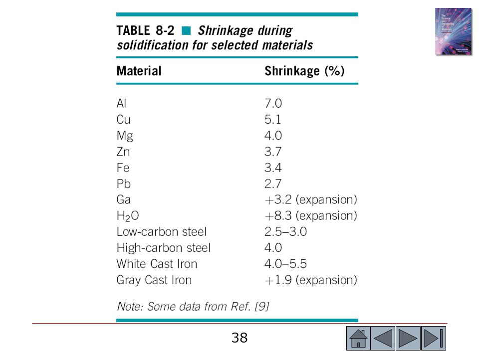
Shrinkage - Contraction of a casting during solidification. Microshrinkage - Small, frequently isolated pores between the dendrite arms formed by the shrinkage that accompanies solidification. Gas porosity - Bubbles of gas trapped within a casting during solidification, caused by the lower solubility of the gas in the solid compared with that in the liquid. Sievert’s law - The amount of a gas that dissolves in a metal is proportional to the partial pressure of the gas in the surroundings.

39
©2003 Brooks/Cole, a division of Thomson Learning, Inc
©2003 Brooks/Cole, a division of Thomson Learning, Inc. Thomson Learning™ is a trademark used herein under license. Figure Several types of macroshrinkage can occur, including cavities and pipes. Risers can be used to help compensate for shrinkage

40
Example 8.6 Design of a Riser for a Casting
Design a cylindrical riser, with a height equal to twice its diameter, that will compensate for shrinkage in a 2 cm 8 cm 16 cm casting (Figure 8.16). ©2003 Brooks/Cole, a division of Thomson Learning, Inc. Thomson Learning™ is a trademark used herein under license. Figure The geometry of the casting and riser (for Example 8.6)
. ©2003 Brooks/Cole, a division of Thomson Learning, Inc. Thomson Learning™ is a trademark used herein under license. Figure 8.16 The geometry of the casting and riser (for Example 8.6)")
41
Example 8.6 SOLUTION We know that the riser must freeze after the casting. To be conservative, however, we typically require that the riser take 25% longer to solidify than the casting. Therefore:

42
Example 8.6 SOLUTION (Continued)
")
43
©2003 Brooks/Cole, a division of Thomson Learning, Inc
©2003 Brooks/Cole, a division of Thomson Learning, Inc. Thomson Learning™ is a trademark used herein under license. Figure (a) Shrinkage can occur between the dendrite arms. (b) Small secondary dendrite arm spacings result in smaller, more evenly distributed shrinkage porosity. (c) Short primary arms can help avoid shrinkage. (d) Interdendritic shrinkage in an aluminum alloy is shown (x 80)
 Shrinkage can occur between the dendrite arms. (b) Small secondary dendrite arm spacings result in smaller, more evenly distributed shrinkage porosity. (c) Short primary arms can help avoid shrinkage. (d) Interdendritic shrinkage in an aluminum alloy is shown (x 80)")
44
©2003 Brooks/Cole, a division of Thomson Learning, Inc
©2003 Brooks/Cole, a division of Thomson Learning, Inc. Thomson Learning™ is a trademark used herein under license. Figure The solubility of hydrogen gas in aluminum when the partial pressure of H2 = 1 atm.

45
Example 8.7 Design of a Degassing Process for Copper
After melting at atmospheric pressure, molten copper contains 0.01 weight percent oxygen. To assure that your castings will not be subject to gas porosity, you want to reduce the weight percent to less than % prior to pouring. Design a degassing process for the copper.

46
Example 8.7 SOLUTION In one approach, the liquid copper is placed in a vacuum chamber; the oxygen is then drawn from the liquid and carried away into the vacuum. The vacuum required can be estimated from Sievert’s law: Another approach would be to introduce a copper-15% phosphorous alloy. The phosphorous reacts with oxygen to produce P2O5, which floats out of the liquid, by the reaction: 5O + 2P P2O5

47
Section 8.9 Casting Processes for Manufacturing Components
Sand casting - A casting process using sand molds. Investment casting - A casting process that is used for making complex shapes such as turbine blades, also known as the lost wax process. Lost foam process - A process in which a polymer foam is used as a pattern to produce a casting. Permanent mold casting - A casting process in which a mold can be used many times. Pressure die casting - A casting process in which molten metal/alloys is forced into a die under pressure.

48
©2003 Brooks/Cole, a division of Thomson Learning, Inc
©2003 Brooks/Cole, a division of Thomson Learning, Inc. Thomson Learning™ is a trademark used herein under license. Figure 8.19 Four typical casting processes: (a) and (b) Green sand molding, in which clay-bonded sand is packed around a pattern. Sand cores can produce internal cavities in the casting. (c) The permanent mold process, in which ,metal is poured into an iron or steel mold. (d) Die casting, in which metal is injected at high pressure into a steel die. (e) Investment casting, in which a wax pattern is surrounded by a ceramic; after the wax is melted and drained, metal is poured into the mold
 and (b) Green sand molding, in which clay-bonded sand is packed around a pattern. Sand cores can produce internal cavities in the casting. (c) The permanent mold process, in which ,metal is poured into an iron or steel mold. (d) Die casting, in which metal is injected at high pressure into a steel die. (e) Investment casting, in which a wax pattern is surrounded by a ceramic; after the wax is melted and drained, metal is poured into the mold.")
49
Figure 8-20 Engine block produced using the lost foam casting process
Figure 8-20 Engine block produced using the lost foam casting process. (Courtesy of Paul Arch, Nova Chemicals.)
")
50
Section 8.10 Continuous Casting and Ingot Casting
Ingot casting - The process of casting ingots.This is different from the continuous casting route. Continuous casting - A process to convert molten metal or an alloy into a semi-finished product such as a slab.

51
Figure 8.21 Summary of steps in the extraction of steels using iron ores, coke and limestone. (Source: Used with permission of the American Iron and Steel Institute.)
.")
52
©2003 Brooks/Cole, a division of Thomson Learning, Inc
©2003 Brooks/Cole, a division of Thomson Learning, Inc. Thomson Learning™ is a trademark used herein under license. Figure Vertical continuous casting, used in producing many steel products. Liquid metal contained in the tundish partially solidifies in a mold

53
Figure 8.23 Secondary processing steps in processing of steel and alloys. (Source: Used with permission of the American Iron and Steel Institute.)
.")
54
Example 8.8 Design of a Continuous Casting Machine
Figure 8.24 shows a method for continuous casting of 0.25-in.-thick, 48-in.-wide aluminum plate that is subsequently rolled into aluminum foil. The liquid aluminum is introduced between two large steel rolls that slowly turn. We want the aluminum to be completely solidified by the rolls just as the plate emerges from the machine. The rolls act as a permanent mold with a mold constant B of about 5 min/in.2 when the aluminum is poured at the proper superheat. Design the rolls required for this process.

55
©2003 Brooks/Cole, a division of Thomson Learning, Inc
©2003 Brooks/Cole, a division of Thomson Learning, Inc. Thomson Learning™ is a trademark used herein under license. Figure 8.24 Horizontal continuous casting of aluminum (for Example 8.8)
")
56
Example 8.8 SOLUTION The average thickness is (0.50 in in.)/2 = in. Then: V = (thickness)(length)(width) = 0.375lw A = 2(length)(width) = 2lw V/A = (0.375lw)/(2lw) = in.
(width) = 2lw. V/A = (0.375lw)/(2lw) = in.")
57
Example 8.8 SOLUTION (Continued)
In selecting our final design, we prefer to use the largest practical roll diameter to assure high production rates. As the rolls become more massive, however, they and their supporting equipment become more expensive.

58
Section 8.11 Directional Solidification (DS), Single Crystal Growth, and Epitaxial Growth
Directional solidification (DS) - A solidification technique in which cooling in a given direction leads to preferential growth of grains in the opposite direction, leading to an anisotropic-oriented microstructure. Bridgman processes - A process to grow semiconductor and other single crystals. Epitaxial growth - Growth of a material via epitaxy. Homoepitaxy - Growth of a highly oriented material onto a crystal of the same material. Heteroepitaxy - Growth of a highly oriented material onto a different substrate material.
 - A solidification technique in which cooling in a given direction leads to preferential growth of grains in the opposite direction, leading to an anisotropic-oriented microstructure. Bridgman processes - A process to grow semiconductor and other single crystals. Epitaxial growth - Growth of a material via epitaxy. Homoepitaxy - Growth of a highly oriented material onto a crystal of the same material. Heteroepitaxy - Growth of a highly oriented material onto a different substrate material.")
59
©2003 Brooks/Cole, a division of Thomson Learning, Inc
©2003 Brooks/Cole, a division of Thomson Learning, Inc. Thomson Learning™ is a trademark used herein under license. Figure Controlling grain structure in turbine blades: (a) conventional equiaxed grains, (b) directionally solidified columnar grains, and (C) single crystal.
 conventional equiaxed grains, (b) directionally solidified columnar grains, and (C) single crystal.")
60
Figure 8.26 (a) Silicon single crystal, (b) silicon wafer, and (c) Bridgman technique. (Courtesy of PhotoDisc/Getty Images.)
.")
61
Section 8.12 Solidification of Polymers and Inorganic Glasses
Lamellar - A plate-like arrangement of crystals within a material. Spherulite - Spherical-shaped crystals produced when certain polymers solidify. Preform - A component from which a fiber is drawn or a bottle is made.

62
Figure 8. 27 An amorphous boundary region separates the lamellae
Figure 8.27 An amorphous boundary region separates the lamellae. A spherulite in polystyrene (8000). (From R. Young and P. Lovell, Introduction to Polymers, 2nd Ed., Chapman & Hall, 1991).
. (From R. Young and P. Lovell, Introduction to Polymers, 2nd Ed., Chapman & Hall, 1991).")
63
Figure 8. 28 Processing scheme for float glasses. (Source: www
Figure 8.28 Processing scheme for float glasses. (Source:

64
Section 8.13 Joining of Metallic Materials
Brazing - An alloy, known as a filler, is used to join two materials to one another. Soldering - Soldering is a joining process in which the filler has a melting temperature below 450oC, no melting of the base materials occurs. Fusion welding - Joining processes in which a portion of the materials must melt in order to achieve good bonding. Fusion zone - The portion of a weld heated to produce all liquid during the welding process. Solidification of the fusion zone provides joining.

65
©2003 Brooks/Cole, a division of Thomson Learning, Inc
©2003 Brooks/Cole, a division of Thomson Learning, Inc. Thomson Learning™ is a trademark used herein under license. Figure A schematic diagram of the fusion zone and solidification of the weld during fusion welding: (a) initial prepared joint, (b) weld at the maximum temperature, with joint filled with filler metal, and (c) weld after solidification.
 initial prepared joint, (b) weld at the maximum temperature, with joint filled with filler metal, and (c) weld after solidification.")
66
Figure 8.30 Schematic diagram showing interaction between the heat source and the base metal. Three distinct regions in the weldment are the fusion zone, the heat-affected zone, and the base metal. (Source: Reprinted with permission from ‘‘Current Issues and Problems in Welding Science,’’ by S.A. David and T. DebRoy, 1992, Science, 257, pp. 497–502, Fig. 2. Copyright © 1992 American Association for the Advancement of Science.)
.")
67
Figure 8.33 Cooling curve (for Problem 8.45)
©2003 Brooks/Cole, a division of Thomson Learning, Inc. Thomson Learning™ is a trademark used herein under license. Figure Cooling curve (for Problem 8.45)
")
68
Figure 8.34 Cooling curve (for Problem 8.46)
©2003 Brooks/Cole, a division of Thomson Learning, Inc. Thomson Learning™ is a trademark used herein under license. Figure Cooling curve (for Problem 8.46)
")
69
Figure 8.35 Cooling curves (for Problem 8.47)
©2003 Brooks/Cole, a division of Thomson Learning, Inc. Thomson Learning™ is a trademark used herein under license. Figure Cooling curves (for Problem 8.47)
")
70
Figure 8.36 Step-block casting (for Problem 8.56).
©2003 Brooks/Cole, a division of Thomson Learning, Inc. Thomson Learning™ is a trademark used herein under license. Figure Step-block casting (for Problem 8.56).
.")
71
Figure 8.37 Step-block casting (for Problem 8.57).
©2003 Brooks/Cole, a division of Thomson Learning, Inc. Thomson Learning™ is a trademark used herein under license. Figure Step-block casting (for Problem 8.57).
.")
72
Figure 8.38 Casting to be risered (for Problem 8.97).
©2003 Brooks/Cole, a division of Thomson Learning, Inc. Thomson Learning™ is a trademark used herein under license. Figure Casting to be risered (for Problem 8.97).
.")
73
©2003 Brooks/Cole, a division of Thomson Learning, Inc
©2003 Brooks/Cole, a division of Thomson Learning, Inc. Thomson Learning™ is a trademark used herein under license. Figure 8.18 (repeated for Problem 8.67) The solubility of hydrogen gas in aluminum when the partial pressure of H2 = 1 atm.
 The solubility of hydrogen gas in aluminum when the partial pressure of H2 = 1 atm.")
74
©2003 Brooks/Cole, a division of Thomson Learning, Inc
©2003 Brooks/Cole, a division of Thomson Learning, Inc. Thomson Learning™ is a trademark used herein under license. Figure 8.11 (Repeated for Problem 8.99) The effect of the secondary dendrite arm spacing on the properties of an aluminum casting alloy.
 The effect of the secondary dendrite arm spacing on the properties of an aluminum casting alloy.")
Similar presentations


>")


>")


