Download presentation
Presentation is loading. Please wait.

1
Data Models

2
A data model is an abstraction of a complex real-world data environment.
Data model is the relatively simple representation, usually graphical, of complex real-world data structures. The model’s main function is to help us understand the complexities of the real-world environment. Within the database environment, a data model represents data structures and their characteristics, relations, constraints, and transformation Among database practitioners, the terms data model and database model are often used interchangeably but we will use database model to refer to a specific implementation of a data model

3
The database designer employs data models as communication tools to facilitate the interaction among the designer, the applications programmer, and the end user. If a data model is developed well, it can foster a much improved understanding of the organization for which the database design is developed. A good database design is the foundation for good applications and a good database design uses an appropriate data model as its foundation Data model is an abstraction, meaning one cannot draw a required data out of a data model

4
Characteristics of Data Model
A data model must show some degree of conceptual simplicity without compromising the semantic completeness of the database. It does not make sense to have a data model that is more difficult to conceptualize than the real world. A data model must represent the real world as closely as possible. This goal is more easily realized by adding more semantics to the model’s data representation. (Semantics concern the dynamic data behavior, while data representation constitutes the static aspect of the real-world scenario.) Representation of the real-world transformations (behavior) must be in compliance with the consistency and integrity characteristics of any data model.
 Representation of the real-world transformations (behavior) must be in compliance with the consistency and integrity characteristics of any data model.")
5
Data model basic building blocks
The basic building blocks of all data models are entities, attributes, and relationships. An entity is anything, such as a person, place, thing, or event, about which data are to be collected and stored. Entities may be physical objects such as customers or products. But entities may also be abstractions such as flight routes or musical concerts An attribute is a characteristic of an entity. For example, a CUSTOMER entity would be described by attributes such as customer last name, customer first name, customer phone etc. The attributes are the equivalent of fields in file systems

6
A relationship describes an association among (two or more) entities
A relationship describes an association among (two or more) entities. For example, there is a relationship between customers and Agents that may be described as “ an agent can serve many customers and each customer may be served by one agent”. Data models use three types of relationships: one-to-many, many-to-many, and one-to-one. Database designers usually use the shorthand notations 1:M, M:N, and I:I for them respectively. Although the M:N notation is a standard label for the many-to-many relationship, the label M:M may also be used.
 entities. For example, there is a relationship between customers and Agents that may be described as an agent can serve many customers and each customer may be served by one agent . Data models use three types of relationships: one-to-many, many-to-many, and one-to-one. Database designers usually use the shorthand notations 1:M, M:N, and I:I for them respectively. Although the M:N notation is a standard label for the many-to-many relationship, the label M:M may also be used.")
7
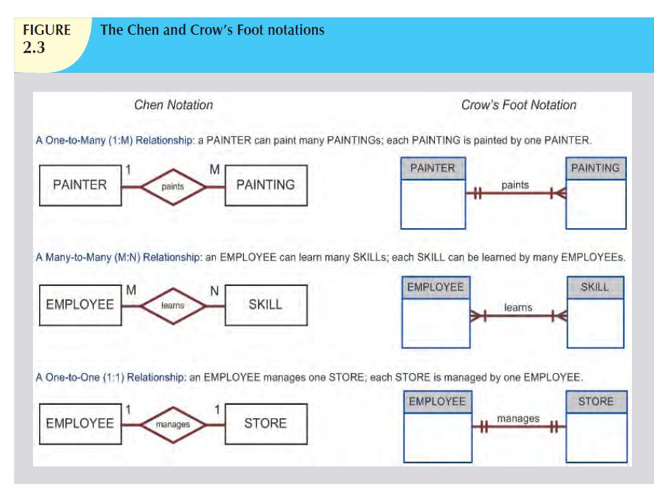
Examples One-to-many (1:M) relationship: A painter paints many different paintings, but each one of them is painted by only one painter. Therefore, database designers label the relationship “PAINTER paints PAINTING” as 1:M Many-to-many (M:N or M:M) relationship: An employee might learn many job skills, and each job skill might be learned by many employees. Database designers label the relationship “EMPLOYEE learns SKILL” as M:N. One-to-one (1:1) relationship: A retail company’s management structure may require that each one of its stores be managed by a sing employee. The relationship “EMPLOYEE manages STORE” is labeled 1:1
 relationship: A painter paints many different paintings, but each one of them is painted by only one painter. Therefore, database designers label the relationship PAINTER paints PAINTING as 1:M. Many-to-many (M:N or M:M) relationship: An employee might learn many job skills, and each job skill might be learned by many employees. Database designers label the relationship EMPLOYEE learns SKILL as M:N. One-to-one (1:1) relationship: A retail company’s management structure may require that each one of its stores be managed by a sing employee. The relationship EMPLOYEE manages STORE is labeled 1:1.")
8
Business Rules How do database designers go about selecting or determining the entities, attributes, and relationships that will build a data model? From a database point of view, the collection of data becomes meaningful only when it reflects properly defined business rules. A business rule is a brief, precise, and unambiguous description of a policy, procedure, or principle within a specific organization’s environment. In a sense, business rules are minsname: they apply to any organization –a business, a government unit, a religious group, or a research laboratory-large or small- that stores and uses data to generate information

9
Business rules, derived from a detailed description of an organization’s operations, help to create and enforce actions within the organization’s environment. Business rules must be rendered in writing and updated to reflect any change in the organization’s operational environment Properly written business rules are used to define entities, attributes, relationships, and constraints.

10
To be effective, business rules must be easy to understand and widely disseminated to ensure that every person in the organization shares a common interpretation of such rules. Business rules describe the main and distinguishing characteristics of the data as viewed by the company.

11
Examples of business rules
A customer may make many payments on an account Each payment on an account is credited to only one customer A customer may generate many invoices Each invoice is generated by only one customer Note that these business rules establish entities, relationships, and constraints

12
The main sources of business rules are company managers, policy makers, department managers, and written documentation such as company’s procedures, standards, or operations manual. A faster and more direct source of business rules is direct interviews with end users. Knowing the business rules promote the creation of an accurate data model based on how the organization actually works and what role is played by the data within that organization’s operations. The database designer must identify the organization’s business rules and analyze their impact on the nature, role, and scope of data

13
Importance of Business rules
They help standardize the company’s view of data They constitute a communications tool between users and designers They allow the designer to understand the nature, role, and scope of the data They allow the designer to understand business processes They allow the designer to develop appropriate relationship participation rules and constraints Note: not all business rules can be modeled.

14
Naming Conventions During the translation of business rules to data model components, you identify entities, attributes, relationships, and constraints. This identification process includes naming the object in a way that makes the object unique and distinguishable from other objects in the problem domain. Therefore, it is important that you pay special attention to how you name the objects you are discovering. Entity names should be descriptive of the objects in the business environment, and use terminology that is familiar to the users. An attribute name should also be descriptive of the data represented by that attribute. It is also a good practice to prefix the name of an attribute with the name of the entity (or an abbreviation of the entity name) in which it occurs. For example, in the CUSTOMER entity, the customer’s credit limit may be called CUS_CREDIT_LIMIT. The CUS indicates that the attribute is descriptive of the CUSTOMER entity, while CREDIT_LIMIT makes it easy to recognize the data that will be contained in the attribute. The use of a proper naming convention will improve the data model’s ability to facilitate communication among the designer, application programmer, and the end user. In fact, a proper naming convention can go a long way toward making your model self-documenting.
 in which it occurs. For example, in the CUSTOMER entity, the customer’s credit limit may be called CUS_CREDIT_LIMIT. The CUS indicates that the attribute is descriptive of the CUSTOMER entity, while CREDIT_LIMIT makes it easy to recognize the data that will be contained in the attribute. The use of a proper naming convention will improve the data model’s ability to facilitate communication among the designer, application programmer, and the end user. In fact, a proper naming convention can go a long way toward making your model self-documenting.")
15
Evolution of Data models

16
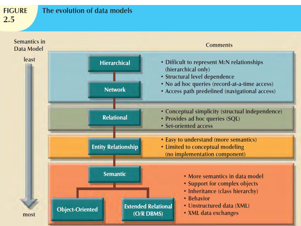
The quest for better data management has led to several models that attempt to resolve the file system’s critical shortcomings. These models represent schools of thought as to what a database is, what it should do, the types of structures that it should employ, and the technology that would be used to implement these structures. Perhaps confusingly, these models are called data models just as are the graphical data models that we have been discussing. This section gives an overview of the major data models in roughly chronological order. You will discover that many of the “new” database concepts and structures bear a remarkable resemblance to some of the “old” data model concepts and structures.

18
The Hierarchical Model
The hierarchical model was developed in the 1960s to manage large amounts of data for complex manufacturing projects such as the Apollo rocket that landed on the moon in 1969. Its basic logical structure is represented by an upside-down tree. The hierarchical structure contains levels, or segments. A segment is the equivalent of a file system’s record type. Within the hierarchy, a higher layer is perceived as the parent of the segment directly beneath it, which is called the child. The hierarchical model depicts a set of one-to-many (1:M) relationships between a parent and its children segments. (Each parent can have many children, but each child has only one parent.) It is data independence but not structural independence
 relationships between a parent and its children segments. (Each parent can have many children, but each child has only one parent.) It is data independence but not structural independence.")
19
Advantages of Hierarchical Model
1. It promotes data sharing. 2. Parent/Child relationship promotes conceptual simplicity. 3. Database security is provided and enforced by DBMS. 4. Parent/Child relationship promotes data integrity. 5. It is efficient with 1:M relationships.

20
Disadvantages 1. Complex implementation requires knowledge of physical data storage characteristics. 2. Navigational system yields complex application development,management, and use; requires knowledge of hierarchical path. 3. Changes in structure require changes in all application programs. 4. There are implementation limitations (no multiparent or M:N relationships). 5. There is no data definition or data manipulation language in the DBMS. 6. There is a lack of standards
. 5. There is no data definition or data manipulation language in the DBMS. 6. There is a lack of standards")
21
Network Model The network model was created to represent complex data relationships more effectively than the hierarchical model, to improve database performance, and to impose a database standard. In the network model, the user perceives the network database as a collection of records in 1:M relationships. However, unlike the hierarchical model, the network model allows a record to have more than one parent. While the network database model is generally not used today, the definitions of standard database concepts that emerged with the network model are still used by modern data models.

22
Some important concepts that were defined at this time are:
The schema, which is the conceptual organization of the entire database as viewed by the database administrator. The subschema, which defines the portion of the database “seen” by the application programs that actually produce the desired information from the data contained within the database. A data management language (DML), which defines the environment in which data can be managed and to work with the data in the database. A schema data definition language (DDL), which enables the database administrator to define the schema components.
, which defines the environment in which data can be managed and to work with the data in the database. A schema data definition language (DDL), which enables the database administrator to define the schema components.")
23
As information needs grew and as more sophisticated databases and applications were required, the network model became too cumbersome. The lack of ad hoc query capability put heavy pressure on programmers to generate the code required to produce even the simplest reports. And although the existing databases provided limited data independence, any structural change in the database could still produce havoc in all application programs that drew data from the database. Because of the disadvantages of the hierarchical and network models, they were largely replaced by the relational data model in the 1980s. It is data independence but not structural independence

24
Advantages 1. Conceptual simplicity is at least equal to that of the hierarchical model. 2. It handles more relationship types, such as M:N and multiparent. 3. Data access is more flexible than in hierarchical and file system models. 4. Data Owner/Member relationship promotes data integrity. 5. There is conformance to standards. 6. It includes data definition language (DDL) and data manipulation language (DML) in DBMS.
 and data manipulation language (DML) in DBMS.")
25
Disadvantages 1. System complexity limits efficiency—still a navigational system. 2. Navigational system yields complex implementation, application development, and management. 3. Structural changes require changes in all application programs.

26
The Relational Model The relational model was introduced in 1970 by E. F. Codd (of IBM) in his landmark paper “A Relational Model of Data for Large Shared Databanks” (Communications of the ACM, June 1970, pp. 377−387). The relational model represented a major breakthrough for both users and designers. To use an analogy, the relational model produced an “automatic transmission” database to replace the “standard transmission” databases that preceded it. Its conceptual simplicity set the stage for a genuine database revolution. The relational model foundation is a mathematical concept known as a relation.
 in his landmark paper A Relational Model of Data for Large Shared Databanks (Communications of the ACM, June 1970, pp. 377−387). The relational model represented a major breakthrough for both users and designers. To use an analogy, the relational model produced an automatic transmission database to replace the standard transmission databases that preceded it. Its conceptual simplicity set the stage for a genuine database revolution. The relational model foundation is a mathematical concept known as a relation.")
27
To avoid the complexity of abstract mathematical theory, you can think of a relation (sometimes called a table) as a matrix composed of intersecting rows and columns. Each row in a relation is called a tuple. Each column represents an attribute. The relational model also describes a precise set of data manipulation constructs based on advanced mathematical concepts. In 1970, Codd’s work was considered ingenious but impractical. The relational model’s conceptual simplicity was bought at the expense of computer overhead; computers at that time lacked the power to implement the relational model. Fortunately, computer power grew exponentially, as did operating system efficiency. Better yet, the cost of computers diminished rapidly as their power grew. Today even PCs, costing a fraction of what their mainframe ancestors did, can run sophisticated relational database software such as Oracle, DB2, Microsoft SQL Server, MySQL, and other mainframe relational software.

28
The relational data model is implemented through a very sophisticated relational database management system (RDBMS). The RDBMS performs the same basic functions provided by the hierarchical and network DBMS systems, in addition to a host of other functions that make the relational data model easier to understand and implement. Arguably the most important advantage of the RDBMS is its ability to hide the complexities of the relational model from the user. The RDBMS manages all of the physical details, while the user sees the relational database as a collection of tables in which data are stored. The user can manipulate and query the data in a way that seems intuitive and logical. Tables are related to each other through the sharing of a common attribute (value in a column).
.")
29
Although the tables are independent of one another, you can easily associate the data between tables. The relational model provides a minimum level of controlled redundancy to eliminate most of the redundancies commonly found in file systems. The relationship type (1:1, 1:M, or M:N) is often shown in a relational schema. A relational diagram is a representation of the relational database’s entities, the attributes within those entities, and the relationships between those entities.
 is often shown in a relational schema. A relational diagram is a representation of the relational database’s entities, the attributes within those entities, and the relationships between those entities.")
30
A relational table stores a collection of related entities
A relational table stores a collection of related entities. In this respect, the relational database table resembles a file. But there is one crucial difference between a table and a file: A table yields complete data and structural independence because it is a purely logical structure. How the data are physically stored in the database is of no concern to the user or the designer; the perception is what counts. And this property of the relational data model became the source of a real database revolution. Another reason for the relational data model’s rise to dominance is its powerful and flexible query language. For most relational database software, the query language is Structured Query Language (SQL), which allows the user to specify what must be done without specifying how it must be done. The RDBMS uses SQL to translate user queries into instructions for retrieving the requested data. SQL makes it possible to retrieve data with far less effort than any other database or file environment.
, which allows the user to specify what must be done without specifying how it must be done. The RDBMS uses SQL to translate user queries into instructions for retrieving the requested data. SQL makes it possible to retrieve data with far less effort than any other database or file environment.")
31
From an end-user perspective, any SQL-based relational database application involves three parts: a user interface, a set of tables stored in the database, and the SQL “engine.” The end-user interface. Basically, the interface allows the end user to interact with the data (by auto-generating SQL code). Each interface is a product of the software vendor’s idea of meaningful interaction with the data. You can also design your own customized interface with the help of application generators that are now standard fare in the database software arena. A collection of tables stored in the database. In a relational database, all data are perceived to be stored in tables. The tables simply “present” the data to the end user in a way that is easy to understand. Each table is independent. Rows in different tables are related by common values in common attributes. SQL engine. Largely hidden from the end user, the SQL engine executes all queries, or data requests. Keep in mind that the SQL engine is part of the DBMS software. The end user uses SQL to create table structures and to perform data access and table maintenance. The SQL engine processes all user requests—largely behind the scenes and without the end user’s knowledge. Hence, it’s said that SQL is a declarative language that tells what must be done but not how it must be done.
. Each interface is a product of the software vendor’s idea of meaningful interaction with the data. You can also design your own customized interface with the help of application generators that are now standard fare in the database software arena. A collection of tables stored in the database. In a relational database, all data are perceived to be stored in tables. The tables simply present the data to the end user in a way that is easy to understand. Each table is independent. Rows in different tables are related by common values in common attributes. SQL engine. Largely hidden from the end user, the SQL engine executes all queries, or data requests. Keep in mind that the SQL engine is part of the DBMS software. The end user uses SQL to create table structures and to perform data access and table maintenance. The SQL engine processes all user requests—largely behind the scenes and without the end user’s knowledge. Hence, it’s said that SQL is a declarative language that tells what must be done but not how it must be done.")
32
Because the RDBMS performs the behind-the-scenes tasks, it is not necessary to focus on the physical aspects of the database. Instead, the concentrate should be on the logical portion of the relational database and its design.

33
The Entity Relationship Model
The conceptual simplicity of relational database technology triggered the demand for RDBMSs. In turn, the rapidly increasing requirements for transaction and information created the need for more complex database implementation structures, thus creating the need for more effective database design tools. (Building a skyscraper requires more detailed design activities than building a doghouse, for example.) Complex design activities require conceptual simplicity to yield successful results. Although the relational model was a vast improvement over the hierarchical and network models, it still lacked the features that would make it an effective database design tool. Because it is easier to examine structures graphically than to describe them in text, database designers prefer to use a graphical tool in which entities and their relationships are pictured. Thus, the entity relationship (ER) model, or ERM, has become a widely accepted standard for data modeling.
 Complex design activities require conceptual simplicity to yield successful results. Although the relational model was a vast improvement over the hierarchical and network models, it still lacked the features that would make it an effective database design tool. Because it is easier to examine structures graphically than to describe them in text, database designers prefer to use a graphical tool in which entities and their relationships are pictured. Thus, the entity relationship (ER) model, or ERM, has become a widely accepted standard for data modeling.")
34
Peter Chen first introduced the ER data model in 1976; it was the graphical representation of entities and their relationships in a database structure that quickly became popular because it complemented the relational data model concepts. The relational data model and ERM combined to provide the foundation for tightly structured database design. ER models are normally represented in an entity relationship diagram (ERD), which uses graphical representations to model database components.
, which uses graphical representations to model database components.")
35
The ER model is based on the following components:

36
ENTITY

37
Entity An entity is anything about which data are to be collected and stored. An entity is represented in the ERD by a rectangle, also known as an entity box. The name of the entity, a noun, is written in the center of the rectangle. The entity name is generally written in capital letters and is written in the singular form: PAINTER rather than PAINTERS, and EMPLOYEE rather than EMPLOYEES. Usually, when applying the ERD to the relational model, an entity is mapped to a relational table. Each row in the relational table is known as an entity instance or entity occurrence in the ER model. Each entity is described by a set of attributes that describes particular characteristics of the entity.

38
Note A collection of like entities is known as an entity set. For example, you can think of the AGENT file as a collection of three agents (entities) in the AGENT entity set. Technically speaking, the ERD depicts entity sets. Unfortunately, ERD designers use the word entity as a substitute for entity set
 in the AGENT entity set. Technically speaking, the ERD depicts entity sets. Unfortunately, ERD designers use the word entity as a substitute for entity set.")
39
Advantages 1. Structural independence is promoted by the use of independent tables. Changes in a table’s structure do not affect data access or application programs. 2. Tabular view substantially improves conceptual simplicity, thereby promoting easier database design, implementation, management, and use. 3. Ad hoc query capability is based on SQL. 4. Powerful RDBMS isolates the end user from physical-level details and improves implementation and management simplicity.

40
Disadvantages 1. The RDBMS requires substantial hardware and system software overhead. 2. Conceptual simplicity gives relatively untrained people the tools to use a good system poorly, and if unchecked, it may produce the same data anomalies found in file systems. 3. It may promote “islands of information” problems as individuals and departments can easily develop their own applications.

41
Relational Model is structural and data independence

42
RELATIONSHIPS

43
Relationships Relationships describe associations among data. Most relationships describe associations between two entities. When the basic data model components were introduced, three types of relationships among data were illustrated: one-to-many (1:M), many-to-many (M:N), and one-to-one (1:1). The ER model uses the term connectivity to label the relationship types. The name of the relationship is usually an active or passive verb. For example, a PAINTER paints many PAINTINGs; an EMPLOYEE learns many SKILLs; an EMPLOYEE manages a STORE.
, many-to-many (M:N), and one-to-one (1:1). The ER model uses the term connectivity to label the relationship types. The name of the relationship is usually an active or passive verb. For example, a PAINTER paints many PAINTINGs; an EMPLOYEE learns many SKILLs; an EMPLOYEE manages a STORE.")
44
ER Notations We can show the different types of relationships using two ER notations: the original Chen notation and the more current Crow’s Foot notation. The Chen notation is based on Peter Chen’s landmark paper. In this notation, the connectivities are written next to each entity box. Relationships are represented by a diamond connected to the related entities through a relationship line. The relationship name is written inside the diamond.

45
Crow Foot Notation The name “Crow’s Foot” is derived from the three-pronged symbol used to represent the “many” side of the relationship. connectivities are represented by symbols. Most data modeling tools let you select the Crow’s Foot notation. Microsoft Visio Professional software was used to generate the Crow’s Foot designs

47
Its exceptional visual simplicity makes the ER model the dominant database modeling and design tool.
Nevertheless, the search for better data-modeling tools continues as the data environment continues to evolve.

48
Advantages 1. Visual modeling yields exceptional conceptual simplicity. 2. Visual representation makes it an effective communication tool. 3. It is integrated with dominant relational model.

49
Disadvantages There is limited constraint representation.
There is limited relationship representation. There is no data manipulation language. Loss of information content occurs when attributes are removed from entities to avoid crowded displays. (This limitation has been addressed in subsequent graphical versions.)
")
50
The Object-Oriented (OO) Model
Increasingly complex real-world problems demonstrated a need for a data model that more closely represented the real world. In the object-oriented data model (OODM), both data and their relationships are contained in a single structure known as an object. In turn, the OODM is the basis for the object-oriented database management system (OODBMS).
, both data and their relationships are contained in a single structure known as an object. In turn, the OODM is the basis for the object-oriented database management system (OODBMS).")
51
An OODM reflects a very different way to define and use entities.
Like the relational model’s entity, an object is described by its factual content. But quite unlike an entity, an object includes information about relationships between the facts within the object, as well as information about its relationships with other objects. Therefore, the facts within the object are given greater meaning. The OODM is said to be a semantic data model because semantic indicates meaning.

52
Subsequent OODM development has allowed an object to also contain all operations that can be performed on it, such as changing its data values, finding a specific data value, and printing data values. Because objects include data, various types of relationships, and operational procedures, the object becomes self-contained, thus making the object—at least potentially—a basic building block for autonomous structures.

53
The OO data model is based on the following components:

54
An object is an abstraction of a real-world entity
An object is an abstraction of a real-world entity. In general terms, an object may be considered equivalent to an ER model’s entity. More precisely, an object represents only one occurrence of an entity. (The object’s semantic content is defined through several of the items in this list.) Attributes describe the properties of an object. For example, a PERSON object includes the attributes Name, Social Security Number, and Date of Birth.
 Attributes describe the properties of an object. For example, a PERSON object includes the attributes Name, Social Security Number, and Date of Birth.")
55
Objects that share similar characteristics are grouped in classes
Objects that share similar characteristics are grouped in classes. A class is a collection of similar objects with shared structure (attributes) and behavior (methods). In a general sense, a class resembles the ER model’s entity set. However, a class is different from an entity set in that it contains a set of procedures known as methods. A class’s method represents a real-world action such as finding a selected PERSON’s name, changing a PERSON’s name, or printing a PERSON’s address. In other words, methods are the equivalent of procedures in traditional programming languages. In OO terms, methods define an object’s behavior. Classes are organized in a class hierarchy. The class hierarchy resembles an upside-down tree in which each class has only one parent. For example, the CUSTOMER class and the EMPLOYEE class share a parent PERSON class. (Note the similarity to the hierarchical data model in this respect.) Inheritance is the ability of an object within the class hierarchy to inherit the attributes and methods of the classes above it. For example, two classes, CUSTOMER and EMPLOYEE, can be created as subclasses from the class PERSON. In this case, CUSTOMER and EMPLOYEE will inherit all attributes and methods from PERSON.
 and behavior (methods). In a general sense, a class resembles the ER model’s entity set. However, a class is different from an entity set in that it contains a set of procedures known as methods. A class’s method represents a real-world action such as finding a selected PERSON’s name, changing a PERSON’s name, or printing a PERSON’s address. In other words, methods are the equivalent of procedures in traditional programming languages. In OO terms, methods define an object’s behavior. Classes are organized in a class hierarchy. The class hierarchy resembles an upside-down tree in which each class has only one parent. For example, the CUSTOMER class and the EMPLOYEE class share a parent PERSON class. (Note the similarity to the hierarchical data model in this respect.) Inheritance is the ability of an object within the class hierarchy to inherit the attributes and methods of the classes above it. For example, two classes, CUSTOMER and EMPLOYEE, can be created as subclasses from the class PERSON. In this case, CUSTOMER and EMPLOYEE will inherit all attributes and methods from PERSON.")
56
Object-oriented data models are typically depicted using Unified Modeling Language (UML) class diagrams. Unified Modeling Language (UML) is a language based on OO concepts that describes a set of diagrams and symbols that can be used to graphically model a system. UML class diagrams are used to represent data and their relationships within the larger UML object-oriented system’s modeling language. The object representation is a simple way to visualize a single object occurrence.
 is a language based on OO concepts that describes a set of diagrams and symbols that can be used to graphically model a system. UML class diagrams are used to represent data and their relationships within the larger UML object-oriented system’s modeling language. The object representation is a simple way to visualize a single object occurrence.")
58
As you examine the diagram, note that:
The object representation of the INVOICE includes all related objects within the same object box. Note that the connectivities (1 and M) indicate the relationship of the related objects to the INVOICE. For example, the 1 next to the CUSTOMER object indicates that each INVOICE is related to only one CUSTOMER. The M next to the LINE object indicates that each INVOICE contains many LINEs. The UML class diagram uses three separate object classes (CUSTOMER, INVOICE, and LINE) and two relationships to represent this simple invoicing problem. Note that the relationship connectivities are represented by the 1..1, 0..*, and 1..* symbols and that the relationships are named in both ends to represent the different “roles” that the objects play in the relationship. The ER model also uses three separate entities and two relationships to represent this simple invoice problem.
 indicate the relationship of the related objects to the INVOICE. For example, the 1 next to the CUSTOMER object indicates that each INVOICE is related to only one CUSTOMER. The M next to the LINE object indicates that each INVOICE contains many LINEs. The UML class diagram uses three separate object classes (CUSTOMER, INVOICE, and LINE) and two relationships to represent this simple invoicing problem. Note that the relationship connectivities are represented by the 1..1, 0..*, and 1..* symbols and that the relationships are named in both ends to represent the different roles that the objects play in the relationship. The ER model also uses three separate entities and two relationships to represent this simple invoice problem.")
59
The OODM advances were felt in many areas, from system modeling to programming.
The added semantics of the OODM allowed for a richer representation of complex objects. This in turn enabled applications to support increasingly complex objects in innovative ways.

60
Advantages 1. Semantic content is added.
2. Visual representation includes semantic content. 3. Inheritance promotes data integrity.

61
Disadvantages Slow development of standards caused vendors to supply their own enhancements, thus eliminating a widely accepted standard. It is a complex navigational system. There is a steep learning curve. High system overhead slows transactions.

62
Newer Data Models: Object/Relational and XML
Facing the demand to support more complex data representations, the relational model’s main vendors evolved the model further and created the extended relational data model (ERDM). The ERDM adds many of the OO model’s features within the inherently simpler relational database structure. The ERDM gave birth to a new generation of relational databases supporting OO features such as objects (encapsulated data and methods), extensible data types based on classes, and inheritance. That’s why a DBMS based on the ERDM is often described as an object/relational database management system (O/R DBMS).
. The ERDM adds many of the OO model’s features within the inherently simpler relational database structure. The ERDM gave birth to a new generation of relational databases supporting OO features such as objects (encapsulated data and methods), extensible data types based on classes, and inheritance. That’s why a DBMS based on the ERDM is often described as an object/relational database management system (O/R DBMS).")
63
The use of complex objects received a boost with the Internet revolution.
When organizations integrated their business models with the Internet, they realized the potential of the Internet to access, distribute, and exchange critical business information. This resulted in the widespread adoption of the Internet as a business communication tool. It is in this environment that Extensible Markup Language (XML) emerged as the de facto standard for the efficient and effective exchange of structured, semistructured, and unstructured data. Organizations using XML data soon realized there was a need to manage the large amounts of unstructured data such as word-processing documents, Web pages, s, diagrams, etc., found in most of today’s organizations. To address this need, XML databases emerged to manage unstructured data within a native XML format At the same time, O/R DBMSs added support for XML-based documents within their relational data structure.
 emerged as the de facto standard for the efficient and effective exchange of structured, semistructured, and unstructured data. Organizations using XML data soon realized there was a need to manage the large amounts of unstructured data such as word-processing documents, Web pages, s, diagrams, etc., found in most of today’s organizations. To address this need, XML databases emerged to manage unstructured data within a native XML format. At the same time, O/R DBMSs added support for XML-based documents within their relational data structure.")
64
The Future of Data Models
Today the O/R DBMS is the dominant database for business applications. Its success could be attributed to the model’s conceptual simplicity, easy-to-use query language, high transaction performance, high availability, security, scalability, and expandability. In contrast, the OO DBMS is popular in niche markets such as computer-aided drawing/computeraided manufacturing (CAD/CAM), geographic information systems (GIS), telecommunications, and multimedia, which require support for complex objects.
, geographic information systems (GIS), telecommunications, and multimedia, which require support for complex objects.")
65
The OO and the relational data models have two totally different approaches.
The OO data model was created to address very specific engineering needs, not the wide-ranging needs of general data management tasks. The relational model was created with a focus on better data management based on a sound mathematical foundation. Given these differences, it is not surprising that the growth of the OO market has been slow compared to the rapid growth of the relational data model. One area in which OO concepts have been very influential is systems development and programming languages.

66
Most contemporary programming languages are object-oriented (Java, Ruby, Perl, C#, .NET, to name a few). Also, there is an increasing need to manage an organization’s unstructured data. It is difficult to speculate on the future development of database models. Will unstructured data management overcome structured data management? We think that each approach complements and augments the other. O/R databases have proven to efficiently support structured and unstructured data management. Furthermore, history has shown that O/R DBMS are remarkably adaptable in supporting ever-evolving data management needs.

67
Two examples of this evolution are:
Hybrid DBMSs are emerging that retain the advantages of the relational model and at the same time provide programmers with an object-oriented view of the underlying data. These types of databases preserve the performance characteristics of the relational model and the semantically rich programmatic support of the object-oriented model. SQL data services, such as Microsoft SQL Data Services (SDS) on its Azure Services Platform, are becoming a critical component of relational database vendors’ Internet service strategies. These “cloud-based” (that is, remotely processed and Internet-based) data services make it possible for companies of any size to store their data in relational databases without incurring expensive hardware, software, and personnel costs, while having access to high-end database features such as failover, backup, high transaction rates, and global data distribution. Companies can use a “pay as you go” system based primarily on their storage and bandwidth utilization and the features used.
 on its Azure Services Platform, are becoming a critical component of relational database vendors’ Internet service strategies. These cloud-based (that is, remotely processed and Internet-based) data services make it possible for companies of any size to store their data in relational databases without incurring expensive hardware, software, and personnel costs, while having access to high-end database features such as failover, backup, high transaction rates, and global data distribution. Companies can use a pay as you go system based primarily on their storage and bandwidth utilization and the features used.")
69
Degrees of Data Abstraction
If you ask 10 database designers what a data model is, you will end up with 10 different answers—depending on the degree of data abstraction. To illustrate the meaning of data abstraction, consider the example of automotive design. A car designer begins by drawing the concept of the car that is to be produced. Next, engineers design the details that help transfer the basic concept into a structure that can be produced. Finally, the engineering drawings are translated into production specifications to be used on the factory floor. As you can see, the process of producing the car begins at a high level of abstraction and proceeds to an ever-increasing level of detail. The factory floor process cannot proceed unless the engineering details are properly specified, and the engineering details cannot exist without the basic conceptual framework created by the designer.

70
Designing a usable database follows the same basic process
Designing a usable database follows the same basic process. That is, a database designer starts with an abstract view of the overall data environment and adds details as the design comes closer to implementation. Using levels of abstraction can also be very helpful in integrating multiple (and sometimes conflicting) views of data as seen at different levels of an organization.
 views of data as seen at different levels of an organization.")
71
In the early 1970s, the American National Standards Institute (ANSI) Standards Planning and Requirements Committee (SPARC) defined a framework for data modeling based on degrees of data abstraction. The ANSI/SPARC architecture (as it is often referred to) defines three levels of data abstraction: external, conceptual, and internal. You can use this framework to better understand database models. The ANSI/SPARC framework has been expanded with the addition of a physical model to explicitly address physical-level implementation details of the internal model.
 defines three levels of data abstraction: external, conceptual, and internal. You can use this framework to better understand database models. The ANSI/SPARC framework has been expanded with the addition of a physical model to explicitly address physical-level implementation details of the internal model.")
72
The External Model The external model is the end users’ view of the data environment. The term end users refers to people who use the application programs to manipulate the data and generate information. End users usually operate in an environment in which an application has a specific business unit focus. Companies are generally divided into several business units, such as sales, finance, and marketing. Each business unit is subject to specific constraints and requirements, and each one uses a data subset of the overall data in the organization. Therefore, end users working within those business units view their data subsets as separate from or external to other units within the organization.

74
Because data are being modeled, ER diagrams will be used to represent the external views.
A specific representation of an external view is known as an external schema.

75
Example To illustrate the external model’s view, examine the data environment of Tiny College. Figure 2.7 presents the external schemas for two Tiny College business units: student registration and class scheduling. Each external schema includes the appropriate entities, relationships, processes, and constraints imposed by the business unit. Also note that although the application views are isolated from each other, each view shares a common entity with the other view. For example, the registration and scheduling external schemas share the entities CLASS and COURSE.

76
Note the entity relationships represented in Figure 2.7. For example:
A PROFESSOR may teach many CLASSes, and each CLASS is taught by only one PROFESSOR; that is, there is a 1:M relationship between PROFESSOR and CLASS. A CLASS may ENROLL many students, and each student may ENROLL in many CLASSes, thus creating an M:N relationship between STUDENT and CLASS. Each COURSE may generate many CLASSes, but each CLASS references a single COURSE. For example, there may be several classes (sections) of a database course having a course code of CIS-420. One of those classes might be offered on MWF from 8:00 a.m. to 8:50 a.m., another might be offered on MWF from 1:00 p.m. to 1:50 p.m., while a third might be offered on Thursdays from 6:00 p.m. to 8:40 p.m. Yet all three classes have the course code CIS-420. Finally, a CLASS requires one ROOM, but a ROOM may be scheduled for many CLASSes. That is, each classroom may be used for several classes: one at 9:00 a.m., one at 11:00 a.m., and one at 1 p.m., for example. In other words, there is a 1:M relationship between ROOM and CLASS.
 of a database course having a course code of CIS-420. One of those classes might be offered on MWF from 8:00 a.m. to 8:50 a.m., another might be offered on MWF from 1:00 p.m. to 1:50 p.m., while a third might be offered on Thursdays from 6:00 p.m. to 8:40 p.m. Yet all three classes have the course code CIS-420. Finally, a CLASS requires one ROOM, but a ROOM may be scheduled for many CLASSes. That is, each classroom may be used for several classes: one at 9:00 a.m., one at 11:00 a.m., and one at 1 p.m., for example. In other words, there is a 1:M relationship between ROOM and CLASS.")
78
The use of external views representing subsets of the database has some important advantages:
It makes it easy to identify specific data required to support each business unit’s operations. It makes the designer’s job easy by providing feedback about the model’s adequacy. Specifically, the model can be checked to ensure that it supports all processes as defined by their external models, as well as all operational requirements and constraints. It helps to ensure security constraints in the database design. Damaging an entire database is more difficult when each business unit works with only a subset of data. It makes application program development much simpler.

79
The Conceptual Model Having identified the external views, a conceptual model is used, graphically represented by an ERD, to integrate all external views into a single view. The conceptual model represents a global view of the entire database as viewed by the entire organization. That is, the conceptual model integrates all external views (entities, relationships, constraints, and processes) into a single global view of the data in the enterprise. Also known as a conceptual schema, it is the basis for the identification and high-level description of the main data objects (avoiding any database model–specific details). The most widely used conceptual model is the ER model. Remember that the ER model is illustrated with the help of the ERD, which is, in effect, the basic database blueprint. The ERD is used to graphically represent the conceptual schema.
 into a single global view of the data in the enterprise. Also known as a conceptual schema, it is the basis for the identification and high-level description of the main data objects (avoiding any database model–specific details). The most widely used conceptual model is the ER model. Remember that the ER model is illustrated with the help of the ERD, which is, in effect, the basic database blueprint. The ERD is used to graphically represent the conceptual schema.")
80
The conceptual model yields some very important advantages.
First, it provides a relatively easily understood bird’s-eye (macro level) view of the data environment. Second, the conceptual model is independent of both software and hardware. Software independence means that the model does not depend on the DBMS software used to implement the model. Hardware independence means that the model does not depend on the hardware used in the implementation of the model. Therefore, changes in either the hardware or the DBMS software will have no effect on the database design at the conceptual level. Generally, the term logical design is used to refer to the task of creating a conceptual data model that could be implemented in any DBMS.
 view of the data environment. Second, the conceptual model is independent of both software and hardware. Software independence means that the model does not depend on the DBMS software used to implement the model. Hardware independence means that the model does not depend on the hardware used in the implementation of the model. Therefore, changes in either the hardware or the DBMS software will have no effect on the database design at the conceptual level. Generally, the term logical design is used to refer to the task of creating a conceptual data model that could be implemented in any DBMS.")
81
The Internal Model Once a specific DBMS has been selected, the internal model maps the conceptual model to the DBMS. The internal model is the representation of the database as “seen” by the DBMS. In other words, the internal model requires the designer to match the conceptual model’s characteristics and constraints to those of the selected implementation model. An internal schema depicts a specific representation of an internal model, using the database constructs supported by the chosen database.

82
The development of a detailed internal model is especially important to database designers who work with hierarchical or network models because those models require very precise specification of data storage location and data access paths. In contrast, the relational model requires less detail in its internal model because most RDBMSs handle data access path definition transparently; that is, the designer need not be aware of the data access path details. Nevertheless, even relational database software usually requires data storage location specification, especially in a mainframe environment. For example, DB2 requires that you specify the data storage group, the location of the database within the storage group, and the location of the tables within the database.

83
Because the internal model depends on specific database software, it is said to be software-dependent. Therefore, a change in the DBMS software requires that the internal model be changed to fit the characteristics and requirements of the implementation database model. When you can change the internal model without affecting the conceptual model, you have logical independence. However, the internal model is still hardware-independent because it is unaffected by the choice of the computer on which the software is installed. Therefore, a change in storage devices or even a change in operating systems will not affect the internal model.

85
The Physical Model The physical model operates at the lowest level of abstraction, describing the way data are saved on storage media such as disks or tapes. The physical model requires the definition of both the physical storage devices and the (physical) access methods required to reach the data within those storage devices, making it both software- and hardware dependent. The storage structures used are dependent on the software (the DBMS and the operating system) and on the type of storage devices that the computer can handle. The precision required in the physical model’s definition demands that database designers who work at this level have a detailed knowledge of the hardware and software used to implement the database design.
 access methods required to reach the data within those storage devices, making it both software- and hardware dependent. The storage structures used are dependent on the software (the DBMS and the operating system) and on the type of storage devices that the computer can handle. The precision required in the physical model’s definition demands that database designers who work at this level have a detailed knowledge of the hardware and software used to implement the database design.")
86
Early data models forced the database designer to take the details of the physical model’s data storage requirements into account. However, the now dominant relational model is aimed largely at the logical rather than the physical level; therefore, it does not require the physical-level details common to its predecessors. Although the relational model does not require the designer to be concerned about the data’s physical storage characteristics, the implementation of a relational model may require physical-level fine-tuning for increased performance. Fine-tuning is especially important when very large databases are installed in a mainframe environment. Yet even such performance fine-tuning at the physical level does not require knowledge of physical data storage characteristics. As noted earlier, the physical model is dependent on the DBMS, methods of accessing files, and types of hardware storage devices supported by the operating system. When you can change the physical model without affecting the internal model, you have physical independence. Therefore, a change in storage devices or methods and even a change in operating system will not affect the internal model.

88
Exercise Generate Business rules for your case study area
Given the business rule(s) you wrote, create the basic Crow’s Foot ERD.
 you wrote, create the basic Crow’s Foot ERD.")
Similar presentations