Download presentation
Presentation is loading. Please wait.

1
A 6 meter 50 Mhz 5 Element Home Spun Yagi?
Joe Perry Jr. Wb6dco Nov 2009 article

2
Pages and Pages of Analysis!
Okay, does anyone really know how to design an E&H beam using metal tubes or wires for that matter. How does the diameter of the metal effect the design? I used EZnec V5. for analysis of models. I used QY4 to manually enter an antenna and optimize. All results seem to show that this 6 meter beam should work right out of the box!

3
What to Design? The basic requirements should be:
50 ohm or 75 ohm Z impedance at the driven element Ground height included Coax input length included Ground resistance included Element diameters included No adjustments needed when installed Design for 26 foot tower height (300 inches) Simple dipole driven element NO MATCHING balun or gamma or any other type of matching needed. The use of a 1:1 balun is considered to minimize SWR return signals Boom length 18 feet
 Simple dipole driven element. NO MATCHING balun or gamma or any other type of matching needed. The use of a 1:1 balun is considered to minimize SWR return signals. Boom length 18 feet.")
4
Why is there not a Perfect Yagi
References: Arrl Antenna Book rd Edition, Chapter 4.

5
50 Mhz Yagi Beam of 5 Elements
I have reported that I started my design from scratch using a dipole of aluminum tube of 1.125” OD for all the elements. I had these tubes left over from an unknown burned out beam used on 20/15/10 meters. I took the main tubes and cut them 12” shorter than the design. I stuck 12” long insert tubes into each end of each element so I can adjust the resonance. No matching networks to be used. Just strait coax to the Driven element.

6
Gain versus Boom Length

7
Joe’s experimental elements
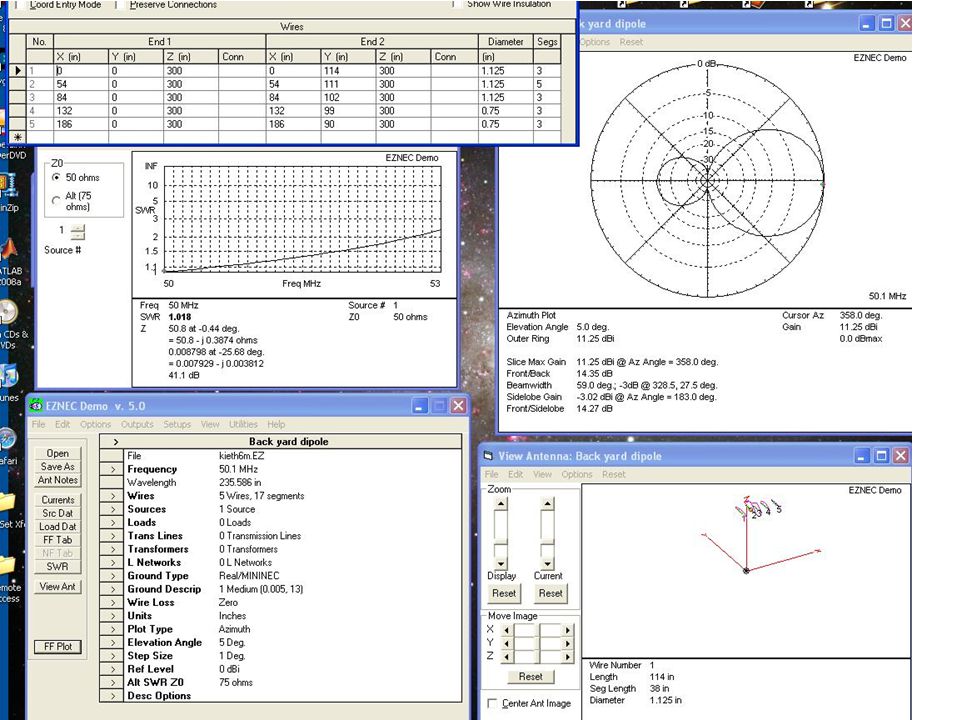
On the next page a picture is the results of using EZnec to just force the 5 element beam to have a good SWR and some Gain and still fit on an old 210” boom. Features: SWR < 1.1 near 50 Mhz to 52 Mhz Gain dBi F/B dB Z = 50.8 ohms on paper! All elements whole numbers in inches.

9
What does QY4 by WA7RAI say about the current elements
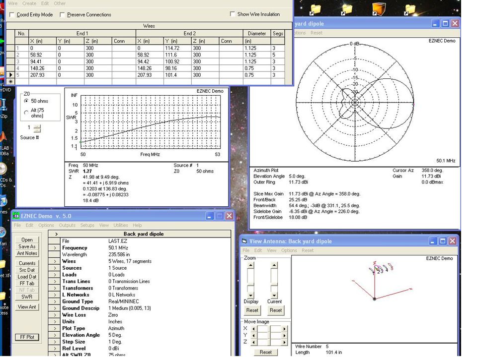
I put Joe’s EZnec design elements into QY4 and used his Optimizations to come up with new elements. I took the new QY4 values and put them back EZnec to see what it says. SWR < 1.5 around 50 Mhz but high elsewhere Gain dBi is the same as original design F/B 25 dB is double the original design Z = 41 ohms a bit lower but not too bad So, over-all this appears a bit better and only slight changes in the spacing and the element lengths. Unfortunately the beam dimensions are now in Tenths of inches. Does this really make it better?

11
Using Joe’s whole inches with new spacings
I put Joe’s original elements in to QY4 and did only a spacing improvement. Then I put those numbers back in EZnec. SWR is < 1.5 from 50 to 51 Mhz Gain is dBi Z = 44 ohms This appears to be better in SWR than the optimized previous elements but not as good as Joe’s original SWR’s over the band

13
Intermediate Testing I have designed a 6 meter beam to cover about 50Mhz to 52 Mhz with less than 1.5 SWR. If the Gain is good and the F/B is as high as it shows on the chart, then this should be a good beam on 50 Mhz. Placing the beam up in the air at lamda/2 will mean putting it on a tower at multiples of c/f = lamda would be like 900,000,000/50,000,000. = 18 feet divided by 2.

14
Assembly of the bolts and tubes
Driven Elements were installed with what we thought was insulation rubberized electrical harness clamps. Reflector and Director mounts used the same rubberized clamps and plates

15
Metal with rubber and Plastic Clamps DO NOT USE
What could go wrong with nice rubberized metal clamps. What you ask!!?? Plastic would avoid the problem of the rubber conducting at high RF frequencies, maybe!

16
The Boom U-clamps Just try and find 1.5” boom clamps. Seems this boom size is not what the current beam companies use so no one had element to boom clamps my size. I ended up buying car exhaust clamps. These are on Ebay or your local auto shop store. They work great.

17
The beam on the box This sure looks like it would work, RIGHT!
Nice boom, nice old metal tubes, nice brackets, nice insulated rubber baby bumpers! The question about elements being insulated from the boom or not insulated has not been answered yet.

18
Metal hose clamps used on the end adjustable elements

19
Here it is for testing in the air
I bolted a 1.5” mast pole and fit that into a set of fiberglass poles that sit in my fence post. Quick and easy way to get it on the air. Don’t climb the tower yet!!

20
Measurements I got out some RG213, brand new with connectors and 50’ long. The driven element of the 6 meter has an SO-239 connector installed. I drilled a hole in one of the poles and installed the threaded connector. I ran a large copper wire to the other driven element and secured it with ¼” stainless bolt.

21
Driven Element Electrical Parts
There is one issue with the methods of connecting your coax to the driven element. One can go direct with the coax and soldering lugs. One can attach an SO-239 feed through with PL-239 connector. On can attach an N type connector if you use N-type-coax with the multiple shields. Which is the best feed is unknown!

22
MFJ 269 Resonator Checker I set the checker to 27 to 70 Mhz range and attached the antenna line. I ran the TUNE knob tell I got close to 50 Mhz. I watched the SWR meter for a dip! Hello DIP..where are you DIPPY… Only a very slight dip at 48 Mhz and the Z impedance ran from 10 to 100 up and down as you scan from 40’s to the 60’s Mhz. There was no DIP and the SWR never got below 5.8?

23
Bad SWR for the 6 meter driven element
The MFJ meter says this driven element is not working correctly. So, I asked on the 2 meter radio today what might be the problem. N6nv came back that most rubber is not an insulator to high RF frequencies. So, I took off all the rubber holders and tried the SWR meter again. This time it worked. Nice 1.5 SWR at about 48 Mhz..

24
Ah-hA Moment I changed the rubber strips to cork strips.
I reinstalled the driven element on the beam boom. The SWR is like 1.2 now and the resonance frequency around 52 Mhz. I also tested with the MFJ meter if the slider tubes on the driven element actually have RF electrical connectivity and change the resonance if you move them in and out.

25
Adding Balun to Driven Element
It is also a good idea to use an "Ugly Balun" or other 1:1 balun capable of 6 meter operation near the feed point to help eliminate rf on the outside of the coax!

26
Coax Loss Table is there a best coax for your frequency range?

27
Power transmission tests
I will first reset all the elements to the best F/B settings and see how the SWR looks. If the SWR is < 1.5 across 50 to like 52 Mhz then I will leave it at those best F/B settings. If not I will attempt to adjust the element lengths. I will now test the 6 meter beam in transmitter mode across town.

28
Beams available now for 6 meters
M2’s M5x gamma 5 elements 307$ Force-12 EF-706 ?matching 7 elements 625$ KLM m7ld ?matching 7 elements 190$ Cushcraft A50-5S gamma 6 elements ?? Hy-Gain VB-64DX gamma 4 element 145$ MJF balun element 99$ Arrow S gamma element 139$ 4 element 155$ JayBeam UK ?matching 4 element 70$

29
Other comparisons

30
Lightening Strike Protection
Meet "The Deputy" -- a high quality gas discharge lightning arrestor. Has standard PL-259/SO-239 male/female fittings, plus an extra nut for optional panel mounting. Rated for legal limit. Let the Deputy arrest your lightning! There are several types of Coax lightening protection devices you put on the coax before it enters your house to the rigs. Don’t be the highest antenna in the area! Air breaks down at about 50,000 Volts per inch so an Air-Gap arrestor may not work with small spikes. Blitz Bugs are coaxial lightning arrester from

Similar presentations


 Feeders & Antennas Chelmsford Amateur.>")


 Antennas Chelmsford Amateur Radio Society.>")


 Used for all mathematical calculations in the radio world. – dB is a logarithmic number dB =10.>")
