Download presentation
Presentation is loading. Please wait.

1
Antenna, Reflector and Radome

2
Antenna Initial single-wavelength (W band) system will use a 15” diameter lens antenna A dual-wavelength feed and lens antenna is planned for the Phase C system Expected performance: Beamwidth 0.6 degrees Gain 48 dBi Sidelobes -24 dB Cross-pol. isol. -30 dB f/D ~ 1.0

3
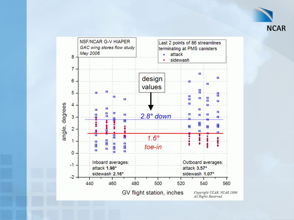
HIAPER Pitch Envelope

5
Reflector Plate Reflector plate rotates independently, nose cone/radome stationary Design to compensate for aircraft pitch envelope: 1° < pitch < 5° Locate plate pivot point at near-field beamwaist a distance, f (15”) from back of lens At beamwaist: beam is 10” 1/e2 (13.5%) power loss Plate flatness: 0.005” rms to have negligeable effect on far-field beam pattern Elliptical design: 15.5” x 0.8% power loss
 from back of lens. At beamwaist: beam is 10 1/e2 (13.5%) power loss. Plate flatness: rms to have negligeable effect on far-field beam pattern. Elliptical design: 15.5 x 0.8% power loss.")
6
Pod Beam Projections: Top and Side Views

7
Radome Sandwich design ensures:
structural integrity (FEA req’d) as well as high transmissivity (one way loss ~ 0.5 dB) functionality at both W-band (94 GHz) and Ka-band (35 GHz) Compensate for radome induced phase errors distorting far-field beam pattern by applying low-loss SAN (styreneacrylonitrile) foam to reflector plate Use ray tracing to determine above compensation
 as well as high transmissivity (one way loss ~ 0.5 dB) functionality at both W-band (94 GHz) and Ka-band (35 GHz) Compensate for radome induced phase errors distorting far-field beam pattern by applying low-loss SAN (styreneacrylonitrile) foam to reflector plate. Use ray tracing to determine above compensation.")
8
Expected Radome Performance
94 GHz

9
Expected Radome Performance
35 GHz

Similar presentations


 R. Struzak School on Digital and Multimedia Communications Using.>")
 IIIT Allahabad. High Gain ( 30-40 db) Low cross polarization Reasonable bandwidth, Fractional Bandwidth being at least.>")