Download presentation
Presentation is loading. Please wait.

1
PHYSICS: FUN EXCITING SIMPLE
Physics 1 REGULAR Module 2 Thermal Physics HEAT ENGINE PHYSICS: FUN EXCITING SIMPLE ap06/p1/thermal/ptG_engines.ppt

2
HEAT ENGINES AND REFRIGERATORS
Heat engines: Entropy (§20.1 p §20.2 p675 §20.5 p682) Heat engines: Carnot cycle (§20.6 p §20.7 p690) Internal Combustion Engines: Otto & Diesel Cycles (§20.3 p678) Refrigerators (§20.4 p680) References: University Physics 12th ed Young & Freedman
 Heat engines: Carnot cycle (§20.6 p684 §20.7 p690) Internal Combustion Engines: Otto & Diesel Cycles (§20.3 p678) Refrigerators (§20.4 p680) References: University Physics 12th ed Young & Freedman.")
3
Heat engine: device that transforms heat partly into work (mechanical energy) by a working substance undergoing a cyclic process.
 by a working substance undergoing a cyclic process.")
4
W > 0 |QH| = |W|+|QC| petrol engine: fuel + air petrol engine - hot exhaust gases + cooling system

5
All heat engines absorb heat QH from a source at a relatively high temperature (hot reservoir TH), perform some work W and reject some heat QC at a lower temperature (cold reservoir TC). First Law for a cyclic process: U = 0 = Qnet – W Qnet = |QH| - |QC| = W Thermal efficiency, e represents the fraction of QH that is converted to useful work.

6
Problem (Y & F Example 20.1) A large truck is travelling at 88 km.h-1. The engine takes in J of heat and delivers J of mechanical energy per cycle. The heat is obtained by burning petrol (heat of combustion Lcomb = 5.0107 J.kg-1). The engine undergoes 25 cycles per second. Density of petrol = 700 kg.m-3 (a) What is the thermal efficiency of the heat engine? (b) How much heat is discarded each cycle? (c) How much petrol is burnt per hour (kg.h-1)? (d) What is the petrol consumption of the truck in L/100 km?
. The engine undergoes 25 cycles per second. Density of petrol = 700 kg.m-3. (a) What is the thermal efficiency of the heat engine (b) How much heat is discarded each cycle (c) How much petrol is burnt per hour (kg.h-1) (d) What is the petrol consumption of the truck in L/100 km")
7
Solution I S E E v = 88 km.h QH = 1.0104 J/cycle W = 2103 J/cycle Lcomb = 5.0107 J.kg-1 f = 25 cycles.s-1 (a) e = ? e = W / QH = (2103) / (1.0104) = 0.20 = 20% sensible (b) QC = ? J |QH| - |QC| = W |QC| = 8.0103 J/cycle
 e = e = W / QH = (2103) / (1.0104) = 0.20 = 20% sensible. (b) QC = J |QH| - |QC| = W |QC| = 8.0103 J/cycle.")
8
(c) QH = 1104 J/cycle QH /t = (25)(1104) J.s-1 = 2.5105 J.s LC = 5.0107 J.kg-1 QH/t = (m/t) Lcomb m/t = (QH/t )/ Lcomb = (2.5105 ) / (5.0107) = 510-3 kg.s-1 m/t = (510-3)(60)(60) = 18 kg.h-1 (d) fuel consumption = ? L/100 km v = 88 km.h-1 v = d/t t = ? h d = 100 km t = d / v = 100 / 88 h = h mass used traveling 100 km m = (m/t)t = (18)(1.1364) = kg = m V L = 1 m3 volume used in traveling 100 km V = m / = ( / 700) m3 = m3 = 29.2 L petrol consumption = L/100 km
 Lcomb m/t = (QH/t )/ Lcomb = (2.5105 ) / (5.0107) = 510-3 kg.s-1. m/t = (510-3)(60)(60) = 18 kg.h-1. (d) fuel consumption = L/100 km. v = 88 km.h-1 v = d/t t = h. d = 100 km. t = d / v = 100 / 88 h = h. mass used traveling 100 km m = (m/t)t = (18)(1.1364) = kg. = m V 103 L = 1 m3. volume used in traveling 100 km V = m / = ( / 700) m3 = m3 = 29.2 L. petrol consumption = 29.2 L/100 km.")
9
Hot Reservoir QH W Engine QC= 0 Surroundings
Can a heat engine be 100% efficient in converting heat into mechanical work ? Why does this engine violate the Second Law ?

10
ENTROPY considerations:
S(engine) = cyclic process S(surrounding) = 0 no heat transfer to surroundings S(hot reservoir) < 0 heat removed S(total) < violates Second Law All heat engines (heat to work): efficiency, e < 1
 = 0 cyclic process. S(surrounding) = 0 no heat transfer to surroundings. S(hot reservoir) < 0 heat removed. S(total) < 0 violates Second Law. All heat engines (heat to work): efficiency, e < 1.")
11
Hot reservoir QH W Engine surroundings QC Cold reservoir

12
S(hot reservoir) = - |QH|/ TH
S(cold reservoir) = + |QC|/ TC S(engine) = 0 (cyclic process) S(surroundings) = 0 (no heat transfer to surroundings) S(total) = - |QH|/ TH + |QC|/ TC Useful work can only be done if S(total) 0 | QH| / TH | QC | / TC
 = + |QC|/ TC. S(engine) = 0 (cyclic process) S(surroundings) = 0 (no heat transfer to surroundings) S(total) = - |QH|/ TH + |QC|/ TC. Useful work can only be done if S(total) 0. | QH| / TH | QC | / TC.")
13
An ideal engine e.g. Carnot Cycle S = 0 | QH / TH | = | QC / TC |
e = W / QH W = |QH| - |QC| e = (|QH| - |QC| / QH)= 1 - |QC| / |QH| e = 1 – TC / TH < 1 Sadi Carnot (1824) Frenchman This is the absolute max efficiency of a heat engine NOTE: All heat (QH & QC) exchanges occurred isothermally in calculating the efficiency e = 1 – TC / TH
= 1 - |QC| / |QH| e = 1 – TC / TH < 1. Sadi Carnot (1824) Frenchman. This is the absolute max efficiency of a heat engine. NOTE: All heat (QH & QC) exchanges occurred isothermally in calculating the efficiency e = 1 – TC / TH.")
14
CARNOT CYCLE Heat engine with the maximum possible efficiency consistent with 2nd law. All thermal processes in the cycle must be reversible - all heat transfer must occur isothermally because conversion of work to heat is irreversible. When the temperature of the working substances changes, there must be zero heat exchange – adiabatic process. Carnot cycle – consists of two reversible isotherms and two reversible adiabats

15
Carnot Cycle P Q W Q V adiabatic isothermals 3 Diagram not to 4 scale,
adiabats are W much steeper than 2 shown 1 Q C released to surroundings V NOTE: All heat (QH & QC) exchanges occurred isothermally in calculating the efficiency e = 1 – TC / TH
 exchanges occurred isothermally in calculating the efficiency e = 1 – TC / TH.")
16
QC QH p V 1 and 2: “cold” 3 and 4: “hot”
1 2 Isothermal compression 2 3 Adiabatic compression 3 4 Isothermal expansion 4 1 Adiabatic expansion All energy exchanges are reversible – there are no non-recoverable energy losses

17
Proof: e = 1 - |QC| / |QH| = 1 - TC / TH
Isothermal change Q = n R T ln(Vf /Vi) 1 2: Isothermal compression heat QC rejected to sink at constant temperature TC. |QC | = n R TC ln(V2 / V1) 3 4: Isothermal expansion heat QH supplied from source at constant temperature |QH | = n R TH ln(V4 / V3) e = 1 - |QC| / |QH| = 1 – TC ln(V2 / V1) / TH ln(V4 / V3) (Eq. 1) 1 and 2: “cold” 3 and 4: “hot” V p 4 3 1 2 Adiabatic change Q = 0 TiVi-1 = TfVf-1
 1 2: Isothermal compression. heat QC rejected to sink at constant. temperature TC. |QC | = n R TC ln(V2 / V1) 3 4: Isothermal expansion. heat QH supplied from source at constant temperature. |QH | = n R TH ln(V4 / V3) e = 1 - |QC| / |QH| = 1 – TC ln(V2 / V1) / TH ln(V4 / V3) (Eq. 1) 1 and 2: cold 3 and 4: hot V. p Adiabatic change Q = 0 TiVi-1 = TfVf-1.")
18
2 3: Adiabatic expansion
In practice, the Carnot cycle cannot be used for a heat engine because the slopes of the adiabatic and isothermal lines are very similar and the net work output (area enclosed by pV diagram) is too small to overcome friction & other losses in a real engine. e = 1 - TC ln(V1 / V2) / TH ln(V4 / V3) (Eq. 1) Efficiency of Carnot engine - max possible efficiency for a heat engine operating between TC and TH
 is too small to overcome friction & other losses in a real engine. e = 1 - TC ln(V1 / V2) / TH ln(V4 / V3) (Eq. 1) Efficiency of Carnot engine - max possible efficiency for a heat engine operating between TC and TH.")
19
TC = 25 oC The strength & hardness of metals decreases rapidly above 750 oC “Re-author” Y&F Example 20.3

20
Diathermal wall: A highly thermally conducting wall.

21
CAR ENGINE The four–stroke OTTO cycle of a conventional petrol engine

22
The four–stroke OTTO cycle of a conventional petrol engine
intake compression ignition power exhaust stroke stroke stroke stroke intake stroke: isobaric expansion compression stroke: adiabatic compression ignition: isochoric heating of gas power stroke: adiabatic expansion of gas exhaust stroke: isochoric cooling of gas / isobaric compression

23
Intake1 Power 3 Compression 2 Exhaust 4

24
cooling of exhaust gases
Otto Cycle P IGNITION fuel combustion 3 adiabatic isothermals QH power stroke 2 compression stroke W 4 cooling of exhaust gases QC 5 1 released to P surroundings o V intake stroke exhaust stroke V2 V1 = r V2 r = compression ratio

25
P Otto Cycle 3 adiabatic isothermals Q H 2 4 Q C released to P 5 1 surroundings o V V V 2 1 5 1: inlet stroke volume increases as piston moves down creating a partial vacuum to aid air/fuel entering cylinder via the open inlet valve.

26
P Otto Cycle 3 adiabatic isothermals Q H 2 4 Q C released to P 5 1 surroundings o V V V 2 1 1 2: compression stroke inlet valve closes piston moves up compressing the air/fuel mixture adiabatically.

27
P Otto Cycle 3 adiabatic isothermals Q H 2 4 Q C released to P 5 1 surroundings o V V V 2 1 2 3: ignition – spark plug fires igniting mixture - constant volume combustion.

28
P Otto Cycle 3 adiabatic isothermals Q H 2 4 Q C P 5 1 released to surroundings o V V V 2 1 3 4: expansion or power stroke – heated gas expands adiabatically as the piston is pushed down doing work (Vmax = r Vmin) Compression ratio, r
. Compression ratio, r.")
29
P Otto Cycle 3 adiabatic isothermals Q H 2 4 Q C released to P 5 1 surroundings o V V V 2 1 4 1 start of Exhaust stroke – outlet valve opens and mixture expelled at constant volume then 1 5

30
P Otto Cycle 3 adiabatic isothermals Q H 2 4 Q C released to P 5 1 surroundings o V V V 2 1 1 5: Exhaust stroke – piston moves up producing a compression at constant pressure, Po (atmospheric pressure).
.")
31
Otto cycle – standard petrol engine (4 stroke)
Idealized model of the thermodynamic processes in a typical car engine. For compression ratio, r ~ 8 and = 1.4 (air) TH (peak) ~ 1800 °C TC (base) ~ 50 °C e ~ 56% (ideal engine) e ~ 35% (real engine). Efficiency increases with larger r engine operates at higher temperatures pre–ignition knocking sound and engine can be damaged. Octane rating – measure of anti-knocking – premium petrol r ~ 12. In practice, the same air does not enter the engine again, but since an equivalent amount of air does enter, we may consider the process as cyclic.
 TH (peak) ~ 1800 °C TC (base) ~ 50 °C. e ~ 56% (ideal engine) e ~ 35% (real engine). Efficiency increases with larger r engine operates at higher temperatures pre–ignition knocking sound and engine can be damaged. Octane rating – measure of anti-knocking – premium petrol r ~ 12. In practice, the same air does not enter the engine again, but since an equivalent amount of air does enter, we may consider the process as cyclic.")
32
Comparison of theoretical and actual pV diagrams for the four-stroke Otto Cycle engine.

33
P Q Q P V V V Diesel Cycle 5 to 1: intake stroke isobaric expansion
1 to 2: compression stroke abiabatic compression 2 to 3: ignition isobaric heating 3 to 4: power stroke adiabatic expansion 4 to 1: exhaust stroke (start) isochoric cooling 1 to 5: exhaust stroke (finish) isobaric compression P Q adiabatic isothermals H 2 3 4 released to Q surroundings P 5 1 C o V V V 2 1 Rudolf Diesel
 isochoric cooling. 1 to 5: exhaust stroke (finish) isobaric compression. P. Q. adiabatic. isothermals. H released to. Q. surroundings. P C. o. V. V. V Rudolf Diesel.")
34
P Diesel Cycle Q Q P V V V adiabatic isothermals 2 3 4 5 1 H C o 2 1
fuel ignition adiabatic isothermals H 2 3 power stroke compression stroke 4 Q cooling of exhaust gases C released to P 5 1 surroundings o V V V 2 1

36
DIESEL CYCLE No fuel in the cylinder at beginning of compression stroke. At the end of the adiabatic compression high temperatures are reached and then fuel is injected fast enough to keep the pressure constant. The injected fuel because of the high temperatures ignites spontaneously without the need for spark plugs. Diesel engines operate at higher temperatures than petrol engines, hence more efficient. For r ~ 18 and = 1.4 (air) TH (peak) ~ 2000 °C TC (base) ~ 50 °C e ~ 68% (ideal engine) real efficiency ~ 40 % Petrol engine ~ 56% (ideal engine) real efficiency ~ 35 %
 TH (peak) ~ 2000 °C TC (base) ~ 50 °C. e ~ 68% (ideal engine) real efficiency ~ 40 % Petrol engine ~ 56% (ideal engine) real efficiency ~ 35 %")
37
Diesel engines Heavier (higher compression ratios), lower power to weight ratio. Harder to start. More efficient than petrol engines (higher compression ratios). No pre-ignition of fuel since no fuel in cylinder during most of the compression They need no carburettor or ignition system, but the fuel-injection system requires expensive high-precision machining. Use cheaper fuels less refined heavy oils – fuel does need to be vaporized in carburettor, fuel less volatile hence safer from fire or explosion. Diesel cycle – can control amount of injected fuel per cycle – less fuel used at low speeds.
. No pre-ignition of fuel since no fuel in cylinder during most of the compression. They need no carburettor or ignition system, but the fuel-injection system. requires expensive high-precision machining. Use cheaper fuels less refined heavy oils – fuel does need to be. vaporized in carburettor, fuel less volatile hence safer from fire or. explosion. Diesel cycle – can control amount of injected fuel per cycle – less fuel used at. low speeds.")
38
These engines were designed primarily for very large container ships.
These engines were designed primarily for very large container ships.

39
Problem For the theoretical Otto cycle, calculate: (a) max cycle temperature (b) work per kilogram of fuel (c) Efficiency (d) Max efficiency Carnot engine working between same temperatures Engine characteristics: cp = kJ.kg-1.K-1 cV = kJ.kg-1.K-1 compression ratio = 8:1 Inlet conditions p = 97.5 kPa and T = 50 oC Heat supplied = 950 kJ.kg-1
 Efficiency. (d) Max efficiency Carnot engine working between same temperatures. Engine characteristics: cp = kJ.kg-1.K-1 cV = kJ.kg-1.K-1. compression ratio = 8:1. Inlet conditions p = 97.5 kPa and T = 50 oC. Heat supplied = 950 kJ.kg-1.")
40
Qp = m cp T QV = m cV T W = |QH| - |QC|
Solution Identify / Setup cp = kJ.kg-1.K-1 cV = kJ.kg-1.K-1 V1/ V2 = 8 p1 = 97.5103 Pa T1 = 50 oC = 323 K QH = 950 kJ.kg-1 TH = T3 = ? K W = ? kJ.kg-1 e = ? eCarnot = ? Adiabatic change Q = 0 T V -1 = constant = cp / cV = / = 1.4 Qp = m cp T QV = m cV T W = |QH| - |QC| e = W / |QH| eCarnot = 1 – TC / TH P Otto Cycle 3 adiabatic isothermals Q H 2 4 Q C released to P 5 1 surroundings o V V V 2 1

41
Adiabatic compression Execute
T2 / T1 = (V1/V2)-1 T2 = T1(V1 / V2)-1 = (323)(8)0.4 K = 742 K Constant volume heating QH = m cV (T3 – T2) T3 = (QH/m)/cV +T2 = (950/ ) K = 2065 K = 1792 oC Adiabatic expansion T4 / T3 = (V3 /V4)-1 T4 = T3(1/8)0.4 = 899 K Constant volume heat rejection QC = m cV (T4 – T3) QC/m = (0.718)( ) kJ.kg-1 = 414 kJ.kg-1 W = |QH| - |QC| = (950 – 414) kJ.kg-1 = 536 kJ.kg-1 e = W / |QH| = 536 / 950 = (real engine < 0.4) eCarnot = 1 – TC / TH = 1 – 323 / 2067 = 0.84
-1. T2 = T1(V1 / V2)-1 = (323)(8)0.4 K = 742 K. Constant volume heating. QH = m cV (T3 – T2) T3 = (QH/m)/cV +T2 = (950/ ) K = 2065 K = 1792 oC. Adiabatic expansion. T4 / T3 = (V3 /V4)-1. T4 = T3(1/8)0.4 = 899 K. Constant volume heat rejection. QC = m cV (T4 – T3) QC/m = (0.718)( ) kJ.kg-1 = 414 kJ.kg-1. W = |QH| - |QC| = (950 – 414) kJ.kg-1 = 536 kJ.kg-1. e = W / |QH| = 536 / 950 = 0.56 (real engine < 0.4) eCarnot = 1 – TC / TH = 1 – 323 / 2067 =")
42
Diesel Cycle Calculate the above quantities for the diesel cycle with a compression ratio = 20 P Q adiabatic isothermals H 2 3 4 released to Q surroundings P 5 1 C o V V V 2 1

43
Adiabatic compression V1 / V2 = 20
T2 / T1 = (V1/V2) T2 = T1(V1 / V2)-1 = (323)(20)0.4 K = 1071 K Isobaric heating QH = m cp (T3-T2) QH/m = cp (T3 –T2) T3 = T2 + (1/cp)(QH/m) = (1/1.005)(950) K = 2016 K Isobaric heating / Adiabatic expansion V2 / T2 = V3 / T3 V3 / V2 = T3 / T2 V4 / V2 = 20 V2 = V4 / 20 V3 / V4 = (1/20)(T3/T2) = (1/20)(2016/1071) = T3V3-1 = T4V4-1 T4 = T3 (V3/V4)-1 = (2016)(0.0941)0.4 = 783 K Isochoric cooling QC = m cv (T4 – T1) QC/m = cv (T4 – T1) = (0.718)(783 – 323) K = kJ.kg-1 W = QH – QC = (950 – 330) kJ = 620 kJ.kg-1 e = W / QH = 620 / 950 = e = 1- QC/QH = 1 – 330/950 = 0.65 The work output and efficiency are considerably higher than for Otto Cycle
-1 T2 = T1(V1 / V2)-1 = (323)(20)0.4 K = 1071 K. Isobaric heating. QH = m cp (T3-T2) QH/m = cp (T3 –T2) T3 = T2 + (1/cp)(QH/m) = (1/1.005)(950) K = 2016 K. Isobaric heating / Adiabatic expansion. V2 / T2 = V3 / T3 V3 / V2 = T3 / T2 V4 / V2 = 20 V2 = V4 / 20. V3 / V4 = (1/20)(T3/T2) = (1/20)(2016/1071) = T3V3-1 = T4V4-1 T4 = T3 (V3/V4)-1 = (2016)(0.0941)0.4 = 783 K. Isochoric cooling. QC = m cv (T4 – T1) QC/m = cv (T4 – T1) = (0.718)(783 – 323) K = kJ.kg-1. W = QH – QC = (950 – 330) kJ = 620 kJ.kg-1. e = W / QH = 620 / 950 = 0.65 e = 1- QC/QH = 1 – 330/950 = The work output and efficiency are considerably higher than for Otto Cycle.")
44
Example Consider two engines, the details of which are given in the following diagrams. For both engines, calculate the heat flow to the cold reservoir and the changes in entropy of the hot reservoir, cold reservoir and engine. Which engine violates the Second Law? What is the efficiency of the working engine?

45
Solution First Law: U = Qnet – W Engine: cyclic process U = 0 Qnet = W |QH| - |QC| |QC | = |QH| - W Engine 1: |QC| = = 800 J Engine 2: |QC| = = 700 J

46
S(total) = - |QH|/ TH + |QC|/ TC
Engine 1: S = ( ) J.K-1 = J.K-1 > 0 Second Law validated Engine 2: S = ( ) J.K-1 = J.K-1 < 0 Second Law not validated Engine 1 is the working engine efficiency, e = (work out / energy input) 100 = (200 / 1000)(100) = 20 %
 J.K-1 = J.K-1 > 0. Second Law validated. Engine 2: S = ( ) J.K-1 = J.K-1 < 0. Second Law not validated. Engine 1 is the working engine. efficiency, e = (work out / energy input) 100. = (200 / 1000)(100) = 20 %")
47
Semester 1, 2007 Examination question (5 marks)
A hybrid petrol-engine car has a higher efficiency than a petrol-only car because it recovers some of the energy that would normally be lost as heat to the surrounding environment during breaking. (a) If the efficiency of a typical petrol-only car engine is 20%, what efficiency could be achieved if the amount of heat loss during breaking is halved? (b) Is it possible to recover all the energy lost as heat during braking and convert it into mechanical energy? Explain your answer.
 If the efficiency of a typical petrol-only car engine is 20%, what efficiency could be achieved if the amount of heat loss during breaking is halved (b) Is it possible to recover all the energy lost as heat during braking and convert it into mechanical energy Explain your answer.")
48
Solution Identify / Setup efficiency Second Law of Thermodynamics 100% of heat can not be transformed into mechanical energy e < 1 Execute (a) Reduce heat loss by half (b) Would require |QC| = 0, this would be a violation of the Second Law
 Reduce heat loss by half. (b) Would require |QC| = 0, this would be a violation of the Second Law.")
49
What is a heat pump ? Better buy this quick: 500 % efficiency

50
cold evaporator gas absorbs heat from interior of frig.
|QH| = |Qc| + |W| cold compressor heats gas by compression hot expansion value rapid expansion: liquid to gas, sudden large drop in temp (~35 oC) condenser gas to liquid (high pressure)
 condenser. gas to liquid (high pressure)")
51
The compressor compresses the gas (e. g. ammonia)
The compressor compresses the gas (e.g. ammonia). The compressed gas heats up as it is pressurized (orange). The gas represents the working substance eg ammonia and the compressor driven by an electric motor does work W. The condenser coils at the back of the refrigerator let the hot ammonia gas dissipate its heat QH. The ammonia gas condenses into ammonia liquid (dark blue) at high pressure gas (gas liquid). The high-pressure ammonia liquid flows through the expansion valve The liquid ammonia immediately boils and vaporizes (light blue), its temperature dropping to about –35 °C by the expansion. This makes the inside of the refrigerator cold by absorption of heat QC . The cold ammonia gas enters the compressor and the cycle repeats.
. The compressed gas heats up as it is pressurized (orange). The gas represents the working substance eg ammonia and the compressor driven by an electric motor does work W. The condenser coils at the back of the refrigerator let the hot ammonia gas dissipate its heat QH. The ammonia gas condenses into ammonia liquid (dark blue) at high pressure gas (gas liquid). The high-pressure ammonia liquid flows through the expansion valve The liquid ammonia immediately boils and vaporizes (light blue), its temperature dropping to about –35 °C by the expansion. This makes the inside of the refrigerator cold by absorption of heat QC . The cold ammonia gas enters the compressor and the cycle repeats.")
52
K = what we want / what we pay for
Refrigeration Cycle Heat engine operating in reverse – it takes heat from a cold place and gives it off at a warmer place, this requires a net input of work. |QH| = |QC| + |W| Best refrigerator – one that removes the greatest amount of heat |QC| from inside the refrigerator for the least expenditure of work |W| coefficient of performance, K (higher K value, better the refrigerator) K = what we want / what we pay for K = extraction of max heat from cold reservoir / least amount of work
 K = what we want / what we pay for. K = extraction of max heat from cold reservoir / least amount of work.")
53
QH p W QC V

54
|QH| = |Qc| + |W|

55
|QH| = |Qc| + |W|

56
|QH| = |Qc| + |W|

57
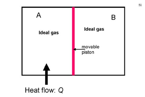
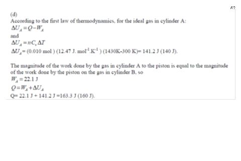
PHYS Exam Question 10 In the figure above, cylinder A is separated from cylinder B by an adiabatic piston which is freely movable. In cylinder A there is mole of an ideal monatomic gas with an initial temperature 300 K and a volume of 1.0x10⁻⁴ m3. In cylinder B, there is mole of the same ideal monatomic gas with the same initial temperature and the same volume as the gas in cylinder A. Suppose that heat is allowed to flow slowly to the gas in cylinder A, and that the gas in cylinder B undergoes the thermodynamic process of adiabatic compression. Heat flows into cylinder A until finally the gas in cylinder B is compressed to a volume of 0.5x10⁻⁵ m3. Assume that CV = J.mol-1.K-1 and the ratio of heat capacities is = (a) Calculate the final temperature and pressure of the ideal monatomic gas in cylinder B after the adiabatic compression. (b) How much work does the gas in cylinder B do during the compression? Explain the meaning of the sign of the work. (c) What is the final temperature of the gas in the cylinder A? (Hint: the pressure exerted by the gas in cylinder A on the piston is equal to that exerted by the gas in cylinder B on the piston.) (d) How much heat flows to the gas in the cylinder A during the process?
 Calculate the final temperature and pressure of the ideal monatomic gas in cylinder B after the adiabatic compression. (b) How much work does the gas in cylinder B do during the compression Explain the meaning of the sign of the work. (c) What is the final temperature of the gas in the cylinder A (Hint: the pressure exerted by the gas in cylinder A on the piston is equal to that exerted by the gas in cylinder B on the piston.) (d) How much heat flows to the gas in the cylinder A during the process")
Similar presentations


 Stirling heat engine Internal combustion engine (Otto cycle) Diesel engine Steam engine (Rankine.>")


>")


, heat(Q),>")

