Download presentation
Presentation is loading. Please wait.

1
Terminal Learning Objective: (TLO)
During this block of instruction you will receive training on identifying the major terrain features, minor terrain features, and colors found on a Military map. Demonstrate the ability to find a point on the map using a protractor, determine the elevation using contour lines on a Military map and demonstrate the ability to use a lensatic compass.

2
Action: Identify the major terrain features, minor terrain features, colors found on a Military map. In addition, demonstrate the ability to find a point on the map using a protractor, determine the elevation using contour lines and determine distance on a Military Map, demonstrate the ability to use a Lensatic Compass, Basic Land Navigation techniques, Intersection, Resection, Triangulation and Military terms and symbols for a Map Overlay. Condition: In a classroom environment, given the student handouts, Prescribed Equipment and a writing utensil. Standards: Achieve 100% on all the written exams as well as participate in the check on learning.

3
Safety: Low. Risk: Low Environmental Considerations: None; Classroom environment Evaluation: You will be evaluated at the end of each block of instruction, and must receive a first time go on each evaluation. The evaluations will be written exams or in class exercises and you must correctly get 100% on each evaluation to pass.

4
Identify key terrain features on a Military Map.
ELO A: Identify key terrain features on a Military Map.

5
Action. Identify key terrain features on a map in 1 minute or less.
Condition: In a classroom environment, given a student handout and a writing utensil. Standard: Demonstrate the ability to match the terrain feature pictured to the label on the left in 1 minute or less.

7
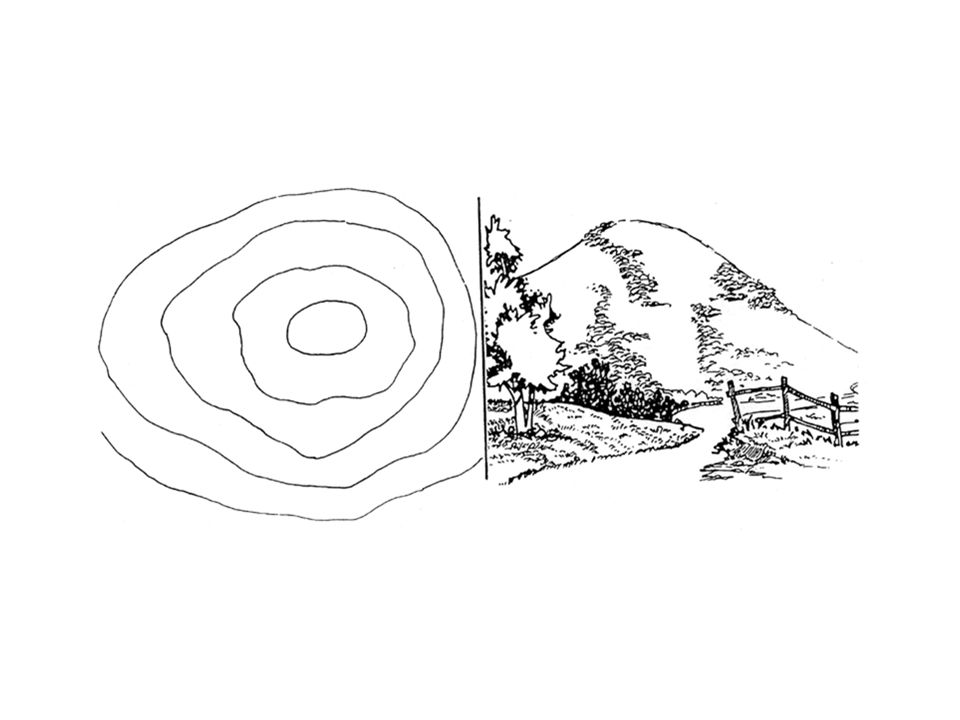
HILL: AN AREA OF HIGH GROUND. FROM
A HILLTOP, THE GROUND SLOPES DOWN IN ALL DIRECTIONS. Contour lines forming concentric circles.

9
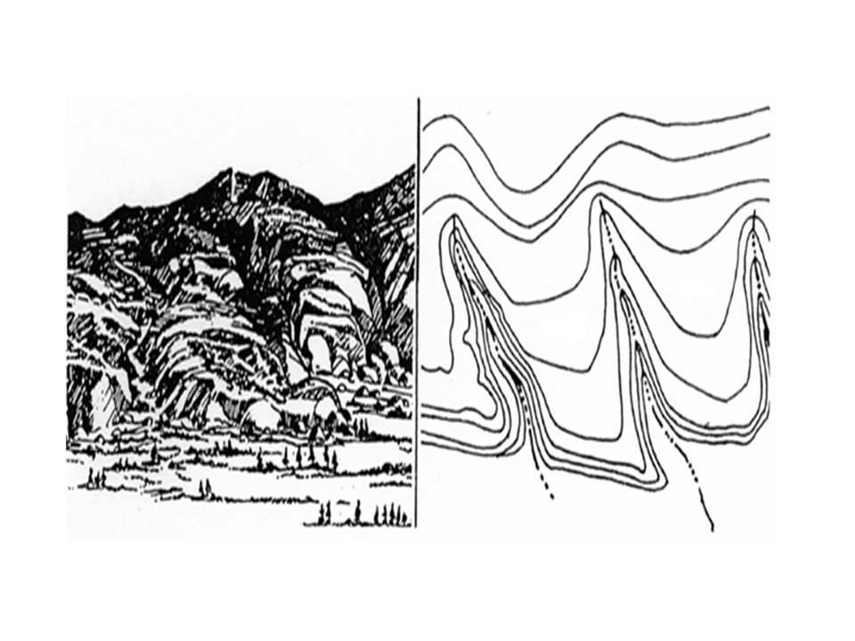
RIDGE: A SLOPING LINE OF HIGH GROUND.
Contour lines forming a U or V; always point to high ground.

11
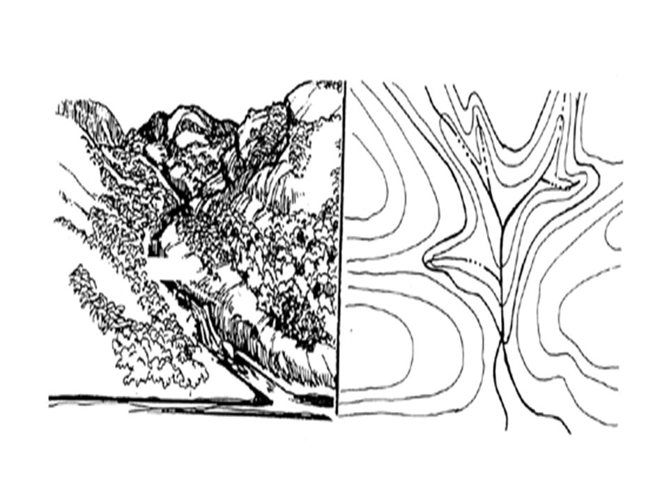
VALLEY: A STRETCHED-OUT GROOVE IN THE LAND, USUALLY FORMED BY
STREAMS OR RIVERS. Contour lines form U lines tend to parallel stream before crossing. Contour line crossing streams ALWAYS point up stream. Usually plenty of room to maneuver

13
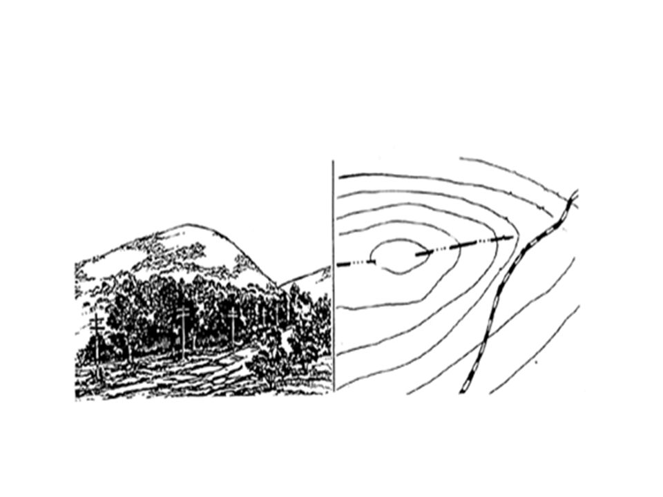
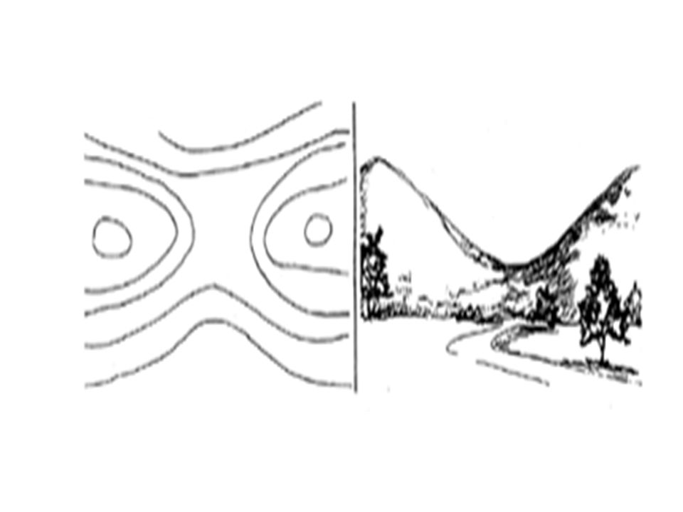
SADDLE: A DIP OR LOW POINT BETWEEN TWO AREAS OF HIGHER GROUND.
Between 2 hilltops or a break in the level crest of a ridge. Saddle usually appear as an hourglass

15
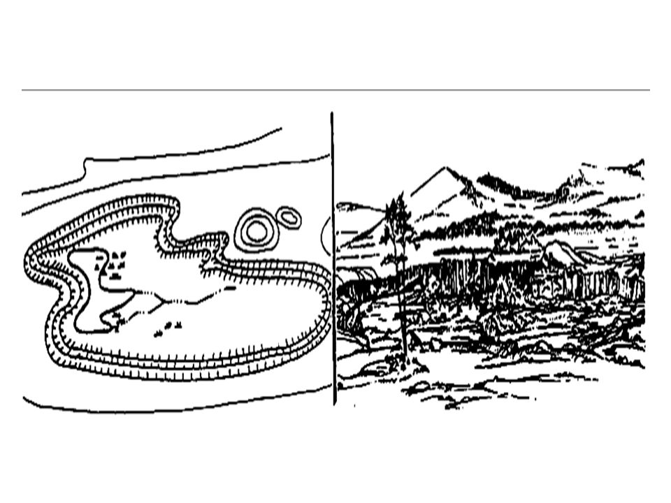
DEPRESSION: A LOW POINT IN THE GROUND
OR SINKHOLE. THEY ARE REPRESENTED BY CLOSE CONTOUR LINES THAT HAVE TICK MARKS POINTING TOWARD LOW GROUND. In a depression there is higher ground on ALL sides

17
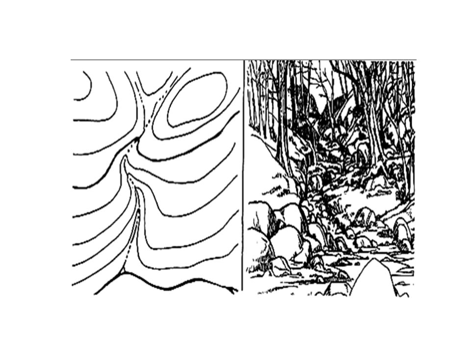
DRAW: A LESS DEVELOPED STREAM COURSE THAN A VALLEY
DRAW: A LESS DEVELOPED STREAM COURSE THAN A VALLEY. THERE IS ESSENTIALLY NO LEVEL GROUND AND, THEREFORE, LITTLE OR NO MANEUVER ROOM WITHIN ITS CONFINES. Contour lines are V Shaped with the points of the V POINTING UPHILL and UPSTREAM

19
SPUR: A SHORT, CONTINUOUS SLOPING LINE OF HIGHER GROUND, NORMALLY JUTTING OUT FROM THE SIDE OF A RIDGE. ususally formed by parallel streams cutting down the side of a ridge Contour lines shaped like U or Vs point AWAY From HIGH GROUND

22
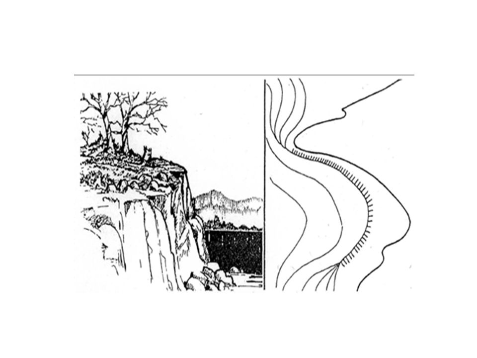
CLIFF: A VERTICAL OR NEAR VERTICAL FEATURE; IT IS AN ABRUPT CHANGE OF THE LAND. THE SLOPE IS SO STEEP THAT THE CONTOUR LINES CONVERGE INTO ONE CONTOUR LINE OR THE LAST CONTOUR LINE HAS TICK MARKS POINTING TO LOW GROUND.

23
Terrain Features Test: (1 Minute)
You have 1 Minute to match the corresponding Terrain Feature pictured with the name in the left column.

24
Terrain Features: Match the corresponding Terrain Feature pictured to the corresponding Terrain Feature. Hill Saddle Depression Cliff

25
Summary: Review: During this lesson you have learned the key Terrain Features that will assist you on your way to becoming more proficient at Terrain Association.

26
ELO B: Identifying the Colors found on a Military Map.

27
Action: Identify the Basic Colors found on a Military Map within 1 minute.
Condition: In a classroom environment, given a student handout and a writing utensil. Standard: Demonstrate the ability to match the Basic Colors found on a Military Map to the Corresponding definition within 1 minute.

28
BLACK: - Indicates cultural (man-made) features such as buildings and roads, surveyed spot elevations, and all labels
 features such as buildings and roads, surveyed spot elevations, and all labels.")
29
BLUE: - Identifies water features such as lakes, swamps, rivers, and drainage

30
BROWN: - Identifies all relief features and elevation, such as contours on older edition maps, and cultivated land on red-light readable maps

31
GREEN: - Identifies vegetation with military significance, such as woods, orchards, and vineyards

32
RED: - Classifies cultural features, such as populated areas, main roads, and boundaries on older maps

33
RED – BROWN: - Combined to identify cultural features, all relief features, non-surveyed spot elevations, and elevation, such as contour lines on red-light readable maps

34
COLORS & DEFINITIONS: Colors Black Blue Brown Green Red Red-Brown
Symbols Black Cultural (Man-Made features) other then roads, and water Blue Water Brown All relief features (minor roads and contour lines) Green Vegetation Red Major, Roads, and built up areas Red-Brown All relief features and roads on red light readable maps
 other then roads, and water. Blue. Water. Brown. All relief features (minor roads and contour lines) Green. Vegetation. Red. Major, Roads, and built up areas. Red-Brown. All relief features and roads on red light readable maps.")
35
Check on Learning: What does the color Green represent on a map?
Vegetation What does the color Brown represent on a map? Contour Lines & all relief features Name the Six colors generally found on a map? Black, Brown, Blue, Green, Red, Red-Brown

36
Colors on a Map Test: You have 1 minute to match the color found on a Military map to the corresponding definition.

37
Colors on a Map: Colors Black Blue Brown Green Red Red-Brown Symbols
All relief features and roads on red light readable maps Blue Major roads and built up areas Brown Vegetation Green Cultural (Man-Made Features) other than roads and water Red All relief features (minor roads and contour lines) Red-Brown Water
 other than roads and water. Red. All relief features (minor roads and contour lines) Red-Brown. Water.")
38
COLORS & DEFINITIONS: Colors Black Blue Brown Green Red Red-Brown
Symbols Black Cultural (Man-Made features) other then roads, and water Blue Water Brown All relief features (minor roads and contour lines) Green Vegetation Red Major, Roads, and built up areas Red-Brown All relief features and roads on red light readable maps
 other then roads, and water. Blue. Water. Brown. All relief features (minor roads and contour lines) Green. Vegetation. Red. Major, Roads, and built up areas. Red-Brown. All relief features and roads on red light readable maps.")
39
Summary: Review: During this block of instruction you have learned how to identify the Basic Colors found on a Military Map.

40
ELO C: Identifying a Grid Coordinate on a Military Map.

41
Action: Determine the grid coordinate within 100 meters of accuracy on a Military Map with in 10 minutes. Condition: In a classroom environment, given a student handout (Map), Protractor (GTA ) and a writing utensil. Standard: Demonstrate the ability to identify the Military feature in the grid coordinate on a Military Map (Student Handout) within 10 minutes. Student must accurately get 4 out of 4 correct to receive a go.
, Protractor (GTA ) and a writing utensil. Standard: Demonstrate the ability to identify the Military feature in the grid coordinate on a Military Map (Student Handout) within 10 minutes. Student must accurately get 4 out of 4 correct to receive a go.")
42
Grid Coordinate Scales. (Protractor)
The primary tool for plotting grid coordinates is the grid coordinate scale. The grid coordinate scale divides the grid square more accurately than can be done by estimation, and the results are more consistent and accurate. Nomenclature: (GTA )
")
43
This device will include at least two coordinate scales, 1:25,000 and 1:50,000 meters. Make sure that when you use this device, you use the correct scale.

44
Military Coordinate Scale and Protractor
1/ 50,000 1/25,000 1/100,000

45
We use this scale for most Military Land Navigation Courses.

46
When reading the protractor each half tick mark equals half of that number. So you will have to estimate if the point does not line up flush with the tick marks.

47
Note. 1. A military map can help you spot your location accurately. The map has vertical lines (top to bottom) and horizontal lines (left to right). These lines form small squares 1,000 meters on each side, called grid squares. 2. The lines that form grid squares are numbered along the outside edge of the map picture. No two grid squares have the same number. 3. The precision of a point location is shown by the number of digits in the coordinates; the more digits, the more precise the location. For example: 1996—A 1,000-meter grid square —To the nearest 100 meters.
 and horizontal lines (left to right). These lines form small squares 1,000 meters on each side, called grid squares. 2. The lines that form grid squares are numbered along the outside edge of the map picture. No two grid squares have the same number. 3. The precision of a point location is shown by the number of digits in the coordinates; the more digits, the more precise the location. For example: 1996—A 1,000-meter grid square —To the nearest 100 meters.")
48
How close a Grid Coordinate can get you.
4 DIGIT GRID COORDINATE TO WITHIN 1,000 METERS A 6 DIGIT GRID COORDINATE TO WITHIN 100 METERS A 8 DIGIT GRID COORDINATE TO WITHIN 10 METERS (50 METER TOLERANCE)
")
49
You have to read the Map from the Right and Up!
This means starting from the bottom Left Hand Side. Read Right to the Grid Line PRIOR TO your Target and then UP TO the Grid line Prior to your Target.

50
Grid Zone Designator EH 12 00 01 00 99 98 154 X

51
Most Military Grid Coordinates are at least 8 Digit Grid Coordinates
Most Military Grid Coordinates are at least 8 Digit Grid Coordinates. The same principals apply as the 6 Digit Grid Coordinate except you will have to break down the numbers on the protractor to nearest amount. For example: The six digit grid coordinate reads EH The 8 Digit Grid Coordinate would read EH You will place the Protractor on the point and read where the Grid Line intersects the protractor and where the center of the point intersects the Protractor.

52
Proper Steps to Use Protractor:
1. Locate the grid square in which the point is located ; the point should already be plotted on the map. 2. The number of the vertical grid line on the left side of the grid square gives the first and second digits of the coordinate.

53
3. The number of the horizontal grid line on the bottom side of the grid square gives the fourth and fifth digits of the coordinate. 4. Place a coordinate scale on the bottom horizontal grid line of the grid square containing the point to determine the third and sixth digits of the coordinate. 5. Check to see that the zeros of the coordinate scale are in the lower right-hand corner of the grid square where the point is located.

54
6. Slide the scale to the right, keeping the bottom of the scale on the bottom grid line until the point is under the vertical (right-hand) scale. To determine the six-digit coordinate, the 100-meter mark on the bottom scale, which is nearest the vertical grid line, is the third digit of the number 115. The 100-meter mark on the vertical scale, which is nearest to the point, is the sixth digit of the number 813. Putting these together, you have

55
2 Letter Grid Identifier:
To determine the correct two-letter 100,000-meter-square identifier, look at the grid reference box in the margin of the map. Place the 100,000-meter-square identifier in front of the coordinate. Example: UV

56
100 METER REFERENCE EH 00 EG 10T EXAMPLE: 123456
SAMPLE 1,000 METER GRID SQUARE 100 METER REFERENCE 46 1. Read large numbers labeling the VERITICAL grid line left of point and estimate tenths (100 meters) from grid line to point 12 3 x Sample point 2. Read large number labeling the HORIZONTAL grid line below point and estimate tenths (100 meters) from grid line to point 45 6 45 12 13 EXAMPLE: 100,000 M. SQUARE IDENTIFICATION WHEN REPORTING OUTSIDE THE 100,000 METER SQUARE AREA IN WHICH THE POINT LIES, PREFIX THE 100,000 METER SQUARE IDENTIFICATION. Example: EG123456 EH 00 EG WHEN REPORTING OUTSIDE THE GRID ZONE DESIGNATION AREA IN WHICH THE POINT LIES, PREFIX THE GRID ZONE DESIGNATION. Example: 10TEG123456 GRID ZONE DESIGNATION 10T
 from grid line to point x. Sample. point. 2. Read large number labeling the HORIZONTAL. grid line below point and estimate tenths (100. meters) from grid line to point EXAMPLE: ,000 M. SQUARE IDENTIFICATION. WHEN REPORTING OUTSIDE THE 100,000. METER SQUARE AREA IN WHICH THE POINT. LIES, PREFIX THE 100,000 METER SQUARE. IDENTIFICATION. Example: EG EH. 00. EG. WHEN REPORTING OUTSIDE THE GRID ZONE. DESIGNATION AREA IN WHICH THE POINT LIES, PREFIX THE GRID ZONE DESIGNATION. Example: 10TEG GRID ZONE DESIGNATION. 10T.")
57
Check on Learning: How close will a 6 Digit Grid Coordinate get to a point on the map? 100 Meters How do you read a Map? Right and Up What goes before any Grid Coordinate? Grid Zone Identifier How do you read a Protractor?

58
Grid Coordinate Test: You will have 10 minutes to correctly identify the Military feature in the correct grid coordinate on a Military Map (Student Handout). Student must accurately get 4 out of 4 correct to receive a go.
. Student must accurately get 4 out of 4 correct to receive a go.")
59
Grid Coordinate Test: EH 092811 Hilltop
What Terrain Feature is located at Grid EH ? Hilltop 2. What Man Made feature is located at Grid EH ? Water Tower 3. What is the 6 Digit Grid Coordinate to Hilltop 155? EH 4. What is the 6 Digit Grid Coordinate to Hilltop 141? EH

60
Summary: During this block of instruction you have received training on how to find a point using a 6 Digit Grid Coordinate on a Military Map.

61
TAKE A BREAK!

62
ELO E: Determine the Distance on a Military Map using Contour Intervals and measurements.

63
Action: Determine the distance between counter intervals and ground distance on a Military Map.
Condition: In a classroom environment, given a student handout (Map), Protractor (GTA ), Military Map (Student Handout) and a writing utensil. Standard: Demonstrate the ability to identify the distance between contour intervals and ground distance on a Military Map with 100% accuracy. The Soldier must accurately answer 4 out of 4 check on learning questions as well as identify the correct contour measurements.
, Protractor (GTA ), Military Map (Student Handout) and a writing utensil. Standard: Demonstrate the ability to identify the distance between contour intervals and ground distance on a Military Map with 100% accuracy. The Soldier must accurately answer 4 out of 4 check on learning questions as well as identify the correct contour measurements.")
64
CONTOUR INTERVALS: Before the elevation of any point on the map can be determined, the user must know the contour interval for the map he is using. The contour interval measurement given in the marginal information is the vertical distance between adjacent contour lines. To determine the elevation of a point on the map— Determine the contour interval and the unit of measure used, for example, feet, meters, or yards.

65
You can find this in the Marginal Information of your Map
You can find this in the Marginal Information of your Map. It will look like the example below.

66
Find the numbered index contour line nearest the point of which you are trying to determine the elevation

67
Determine if you are going from lower elevation to higher, or vice versa. In figure below, point (a) is between the index contour lines. The lower index contour line is numbered 500, which means any point on that line is at an elevation of 500 meters above mean sea level. The upper index contour line is numbered 600, or 600 meters. Going from the lower to the upper index contour line shows an increase in elevation.
 is between the index contour lines. The lower index contour line is numbered 500, which means any point on that line is at an elevation of 500 meters above mean sea level. The upper index contour line is numbered 600, or 600 meters. Going from the lower to the upper index contour line shows an increase in elevation..")
68
Determine the exact elevation of point (a), start at the index contour line numbered 500 and count the number of intermediate contour lines to point (a). Locate point (a) on the second intermediate contour line above the 500-meter index contour line. The contour interval is 20 meters , thus each one of the intermediate contour lines crossed to get to point (a) adds 20 meters to the 500-meter index contour line. The elevation of point (a) is 540 meters; the elevation has increased.
 on the second intermediate contour line above the 500-meter index contour line. The contour interval is 20 meters , thus each one of the intermediate contour lines crossed to get to point (a) adds 20 meters to the 500-meter index contour line. The elevation of point (a) is 540 meters; the elevation has increased..")
69
Determine the elevation of point (b)
Determine the elevation of point (b). Go to the nearest index contour line. In this case, it is the upper index contour line numbered 600. Locate point (b) on the intermediate contour line immediately below the 600-meter index contour line. Below means downhill or a lower elevation. Therefore, point (b) is located at an elevation of 580 meters. Remember, if you are increasing elevation, add the contour interval to the nearest index contour line. If you are decreasing elevation, subtract the contour interval from the nearest index contour line.
. Go to the nearest index contour line. In this case, it is the upper index contour line numbered 600. Locate point (b) on the intermediate contour line immediately below the 600-meter index contour line. Below means downhill or a lower elevation. Therefore, point (b) is located at an elevation of 580 meters. Remember, if you are increasing elevation, add the contour interval to the nearest index contour line. If you are decreasing elevation, subtract the contour interval from the nearest index contour line.")
70
Determine the elevation to a hilltop point (c)
Determine the elevation to a hilltop point (c). Add one-half the contour interval to the elevation of the last contour line. In this example, the last contour line before the hilltop is an index contour line numbered 600. Add one-half the contour interval, 10 meters, to the index contour line. The elevation of the hilltop would be 610 meters.
. Add one-half the contour interval to the elevation of the last contour line. In this example, the last contour line before the hilltop is an index contour line numbered 600. Add one-half the contour interval, 10 meters, to the index contour line. The elevation of the hilltop would be 610 meters.")
71
There may be times when you need to determine the elevation of points to a greater accuracy. To do this, you must determine how far between the two contour lines the point lies. However, most military needs are satisfied by estimating the elevation of points between contour lines

72
If the point is less than one-fourth the distance between contour lines, the elevation will be the same as the last contour line. In the previous figure, the elevation of point a will be 100 meters. To estimate the elevation of a point between one-fourth and three-fourths of the distance between contour lines, add one-half the contour interval to the last contour line.

73
Point b is one-half the distance between contour lines
Point b is one-half the distance between contour lines. The contour line immediately below point b is at an elevation of 160 meters. The contour interval is 20 meters; thus one-half the contour interval is 10 meters. In this case, add 10 meters to the last contour line of 160 meters. The elevation of point b would be about 170 meters.

74
A point located more than three-fourths of the distance between contour lines is considered to be at the same elevation as the next contour line. Point c is located three-fourths of the distance between contour lines. In the previous figure, point c would be considered to be at an elevation of 180 meters.

75
To estimate the elevation to the bottom of a depression, subtract one-half the contour interval from the value of the lowest contour line before the depression. In the figure pictured, the lowest contour line before the depression is 240 meters in elevation. Thus, the elevation at the edge of the depression is 240 meters. To determine the elevation at the bottom of the depression, subtract one-half the contour interval. The contour interval for this example is 20 meters. Subtract 10 meters from the lowest contour line immediately before the depression. The result is that the elevation at the bottom of the depression is 230 meters. The tick marks on the contour line forming a depression always point to lower elevations.

76
In addition to the contour lines, bench marks and spot elevations are used to indicate points of known elevations on the map. (1) Bench marks, the more accurate of the two, are symbolized by a black X, such as X BM 214. The 214 indicates that the center of the X is at an elevation of 214 units of measure (feet, meters, or yards) above mean sea level. To determine the units of measure, refer to the contour interval in the marginal information. (2) Spot elevations are shown by a brown X and are usually located at road junctions and on hilltops and other prominent terrain features. If the elevation is shown in black numerals, it has been checked for accuracy; if it is in brown, it has not been checked.
 Bench marks, the more accurate of the two, are symbolized by a black X, such as X BM 214. The 214 indicates that the center of the X is at an elevation of 214 units of measure (feet, meters, or yards) above mean sea level. To determine the units of measure, refer to the contour interval in the marginal information. (2) Spot elevations are shown by a brown X and are usually located at road junctions and on hilltops and other prominent terrain features. If the elevation is shown in black numerals, it has been checked for accuracy; if it is in brown, it has not been checked.")
77
Measuring Distance on a Military Map:
STRAIGHT-LINE DISTANCE: To determine straight-line distance between two points on a map, lay a straight-edged piece of paper on the map so that the edge of the paper touches both points and extends past them. Make a tick mark on the edge of the paper at each point.

78
STRAIGHT-LINE DISTANCE

79
STRAIGHT-LINE DISTANCE
To convert the map distance to ground distance, move the paper down to the graphic bar scale, and align the right tick mark with a printed number in the primary scale so that the left tick mark is in the extension scale 1000 2000 3000 4000 5000 500 METERS

80
Example: 1000 2000 3000 4000 5000 500 METERS 3350 meters

81
CURVED-LINE DISTANCE To measure distance along a road, stream, or other curved line, the straight edge of a piece of paper is used. In order to avoid confusion concerning the point to begin measuring from and the ending point, an eight-digit coordinate should be given for both the starting and ending points. Place a tick mark on the paper and map at the beginning point from which the curved line is to be measured. Align the edge of the paper along a straight portion and make a tick mark on both map and paper when the edge of the paper leaves the straight portion of the line being measured.

82
CURVED-LINE DISTANCE

83
CURVED-LINE DISTANCE Keeping both tick marks together (on paper and map), place the point of the pencil close to the edge of the paper on the tick mark to hold it in place and pivot the paper until another straight portion of the curved line is aligned with the edge of the paper. Continue in this manner until the measurement is completed.
, place the point of the pencil close to the edge of the paper on the tick mark to hold it in place and pivot the paper until another straight portion of the curved line is aligned with the edge of the paper. Continue in this manner until the measurement is completed.")
84
CURVED-LINE DISTANCE

85
CURVED-LINE DISTANCE When you have completed measuring the distance, move the paper to the graphic scale to determine the ground distance. The only tick marks you will be measuring the distance between are tick marks (a) and (b). The tick marks in between are not used.
 and (b). The tick marks in between are not used.")
86
Check on Learning Where can you find the Countour Interval on the Map?
The Marginal Information How can you determine the elevation to the bottom of a depression? Subtract ½ the contour interval from the value of the lowest contour line before the depression. How are Spot Elevations represented on a Military Map? Shown by a Brown X and are usually located at road junctions and on hilltops and other prominent terrain features. How can you determine the elevation of a hilltop? Add ½ the contour interval to the elevation of the last contour line.

87
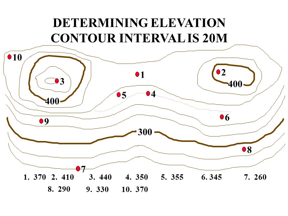
DETERMINING ELEVATION CONTOUR INTERVAL IS 20M
10 2 1 3 400 5 4 400 6 9 300 7 8 6. 345
88
Summary: Review: During this block of instruction you have learned the ability to determine elevation using contour intervals and measure ground distance on a Military Map.

89
ELO F: Demonstrate the ability to use a Lensatic Compass.

90
Action: Demonstrate the ability to use a Lensatic Compass
Condition: In a classroom environment, given a block of instruction and a Lensatic Compass Standard: Demonstrate the ability to use the Lensatic Compass by participating in the check on learning activity at the end of this block of instruction.

91
DIRECTION:

92
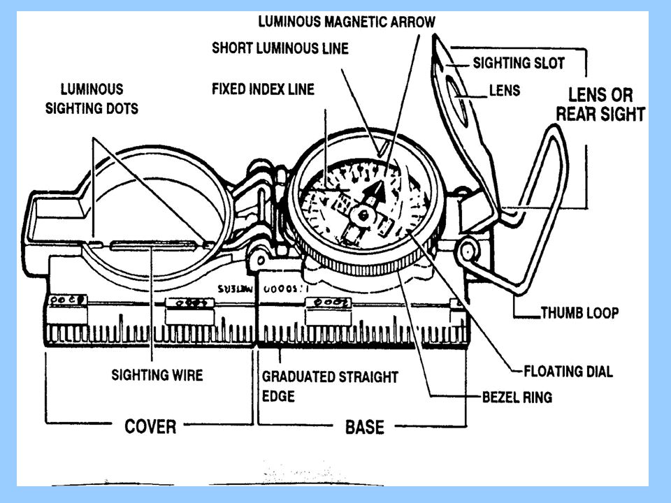
Parts of a Compass Thumb loop Short Luminous line
Luminous sighting dots Luminous arrow, “Magnetic North” Lanyard Sighting wire Graduated straight edge

93
Parts of a Compass Sighting slot Lens Rear sight Fixed index line
Bezel ring Cover Base Floating dial

95
Compass Terms and Concepts
Azimuth An angle measured in a clockwise direction from a north base line. Grid Azimuth East = 90˚ South = 180˚ West = 270˚ North = 360˚ or 0˚ When using an azimuth, the point from which the azimuth originates is imagined to be the center of the azimuth circle.

96
Determine A Grid Azimuth
Plot location of two points Use straight edge to draw line between both points (line must be long enough to cross scale on protractor) Use protractor to determine azimuth
 Use protractor to determine azimuth.")
97
Map Azimuth B A Pt. A EG135801 Pt. B EG158822
When an azimuth is plotted on a map between point A (starting point) and point B (ending point), the points are joined together by a straight line. A protractor is used to measure the angle between grid north and the drawn line, and this measured azimuth is the grid azimuth. Note: The military protractor, GTA , contains two scales: one in degrees (inner scale) and one in mils (outer scale). This protractor represents the azimuth circle. The degree scale is graduated from 0 to 360 degrees; each tick mark on the degree scale represents one degree. A line from 0 to 180 degrees is called the base line of the protractor. Where the base line intersects the horizontal line, between 90 and 270 degrees, is the index or center of the protractor Pt. A EG135801 Pt. B EG158822
 and point B (ending point), the points are joined together by a straight line. A protractor is used to measure the angle between grid north and the drawn line, and this measured azimuth is the grid azimuth. Note: The military protractor, GTA , contains two scales: one in degrees (inner scale) and one in mils (outer scale). This protractor represents the azimuth circle. The degree scale is graduated from 0 to 360 degrees; each tick mark on the degree scale represents one. degree. A line from 0 to 180 degrees is called the base line of the protractor. Where the base line intersects the horizontal line, between 90 and 270 degrees, is the index or center of the protractor. Pt. A EG Pt. B EG")
98
Grid to Magnetic (GM) Angle
To Convert Grid to Magnetic Azimuth Conversion Rule: Left – Add; Right – Subtract (LARS)
")
99
Lensatic Compass

100
Presetting a compass Hold the compass level in the palm of the hand.
Rotate it until the desired azimuth falls under the fixed black index line. Turn the bezel ring until the luminous line is aligned with the north seeking arrow. The compass is now preset. Assume the center hold technique and turn until the north seeking arrow is aligned with the luminous line. Proceed in the direction of the sighting wire.

101
Using the Compass The lensatic compass is used to determine or follow magnetic azimuth both day and night. There are two recommended positions for holding the compass when navigating: Hand to Cheek Method Center Hold Position

102
Center Hold Position Recommend for a predetermined azimuth
(DAY and NIGHT)
")
103
Hand To Cheek Technique
The compass-to-cheek technique is used almost exclusively for sighting It is the best technique for this purpose

104
Compass use at night All the luminous features on the compass will be used. One click on the bezel ring equals; THREE (3) DEGREES
 DEGREES.")
105
Attaining A Magnetic Azimuth
Place the sighting wire on the object Center the sighting notch Look through the lens and read the Red line to obtain the magnetic azimuth

106
Back Azimuth Back Azimuth The reverse direction of a forward azimuth.
Is comparable to doing an about face. MAY BE OBTAINED BY GRID (Protractor) MAGNETIC (Compass) To obtain a back azimuth from an azimuth less than 180˚: Add 180 If the azimuth is 180˚ or more Subtract 180
 MAGNETIC (Compass) To obtain a back azimuth from an azimuth less than 180˚: Add 180. If the azimuth is 180˚ or more. Subtract 180.")
107
Back Azimuth Back Azimuth - azimuth taken from a distant point toward your location Used in Resection Numbers less than add 180 Numbers greater than subtract 180

108
Compass Precautions: Handle with care
The dial is set with a delicate balance and shock could damage it. Reading should never be taken near visible masses of metal or electrical circuits. In cold weather, always carry the compass in its pouch, outside of your layer of clothing.

109
Effects of Metal and Electricity
Metal objects and electrical sources affect the performance of the compass. Suggested separation distance: High-tension power lines 55 meters Field gun, truck, or tank 18 meters Telephone wire/barbed wire 10 meters Machine gun 2 meters Steel helmet or rifle ½ meter

110
Check on Learning What are the two preferred methods of using a Lensatic Compass? Hand to Cheek Method & Center Hold Position One click on the Bezel Ring equals how many degrees? 3 Degrees In converting the GM Angle, what does the acronym LARS mean? Left Add / Right Subtract How do you obtain a back azimuth from an azimuth that is less than 180 Degrees? Add 180 Degrees How do you obtain a back azimuth from an azimuth that is 180 Degrees or greater? Subtract 180 Degrees

111
Summary: Review: During this block of instruction you have learned the ability to utilize a Lensatic Compass.

112
ELO: G Identify the proper technique during a Land Navigation Course.

113
Action: Demonstrate the ability to pay attention and take notes.
Condition: In a classroom environment. Standard: Demonstrate the ability to use the information gathered in class to complete the Land Navigation Course.

114
Basic Land Nav Techniques:
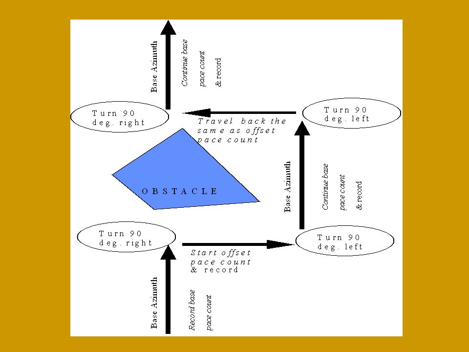
Navigating Past An Obstacle: Basically make a box around the obstacle. Accuracy counts, especially around larger obstacles. A graphical presentation is made of this on the next slide.

116
Pre-Plotting: Consolidate all grid coordinates for given mission and plot on map. Determine order in which points will be negotiated. Determine distance and direction to grid coordinate. Plot. *Convert azimuth to magnetic.

119
Use terrain features to verify your location on the ground
Use terrain features to verify your location on the ground. An individual’s pace count is not exact and must be verified by terrain association. Remember: Add up to 20% to distance if terrain is hilly or rough travel.

120
Determining Pace-count
Note: The following should be done on flat terrain and dense/wooded terrain. Both pace-counts should be memorized by the soldier/cadet. Measure off a distance of exactly 100 meters. Start pacing and counting each time your left foot touches the ground. At the end of the 100 meters turn around and do it again. If your count is 68 steps then your pace-count is 68. Remember this number! Start pacing again through semi-dense vegetation/woods and count each time your left foot touches the ground. At the end of the 100 meters turn around and do it again. Remember this number!

121
Keep track of the paces you have walked in the field
Keep track of the paces you have walked in the field. It is too easy to forget and be off course. Try using some of the following. For every 100 meters try: Move a bead on your pace counter Place a mark in a notebook Tie a knot in a string Put a pebble in your pocket

122
Things that affect Pace Count:
Slope. Pace lengthens on a downgrade and shortens on an upgrade. Winds. Tail winds lengthen pace while head winds shorten pace. Surface. Loose surfaces tend to shorten pace. Elements. Snow, rain and ice tend to shorten pace. Clothing and equipment. Heavier burdens may shorten pace. Stamina. Fatigue will shorten the pace. Limited visibility/night. Unsure footing or the presence of unseen obstacles makes an individual wary and pace will tend to shorten.

123
Things that affect Pace Count:
Physical attributes. Example: One leg may be shorter than the other, causing a tendency to deviate from your course. Unbalanced load. An unbalanced load may pull you slightly off-balance, causing deviation from your intended direction of movement. Movement around obstacles. Right-handed people have an inherent tendency to move to the right around an obstacle, while left-handed people move to the left. A wise navigator alternates his direction of movement around obstacles

124
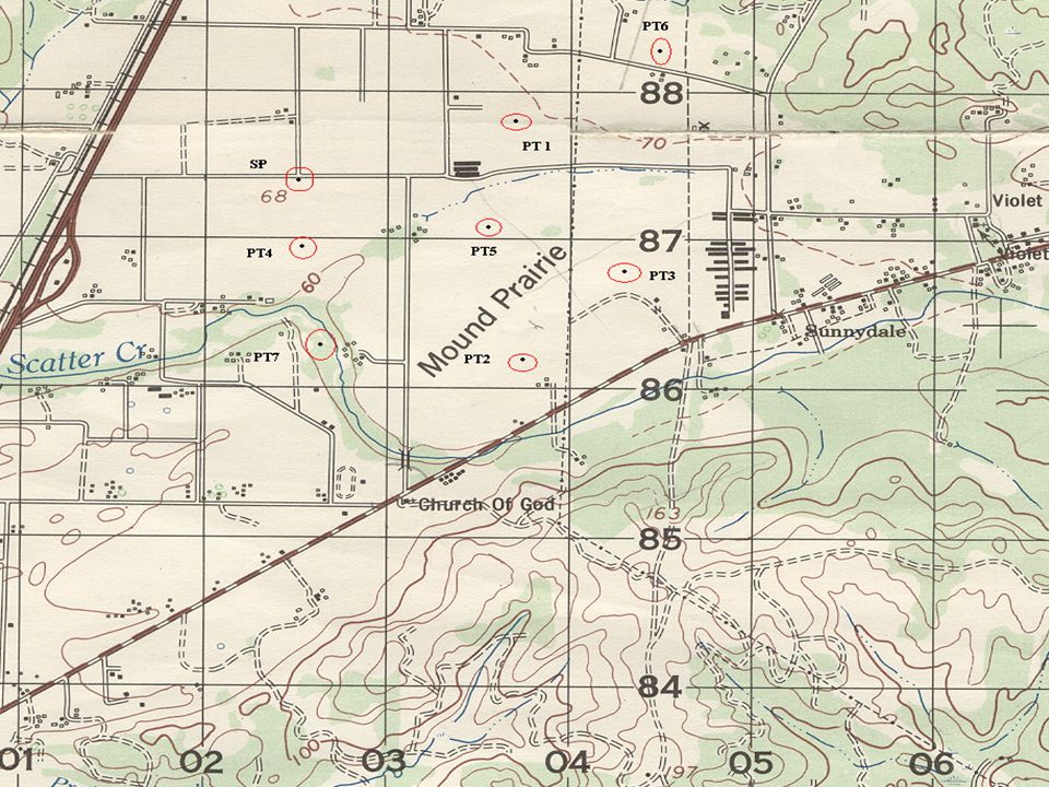
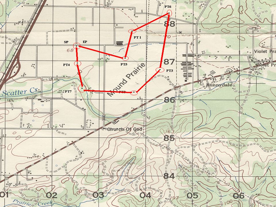
Once you receive your grid coordinates and go to your SP plot all the points on your Map.
Determine the best method to travel and reach each point. Find the direction and distance to each point you plan to travel to. Document each direction and distance to the corresponding point. (Do not mix the points up) Store your map in a zip lock bag to avoid getting damaged by water or other materials. Ensure you place the map and notes in a secure location. Do not lose your map!!! Check after each point and randomly throughout the course.
 Store your map in a zip lock bag to avoid getting damaged by water or other materials. Ensure you place the map and notes in a secure location. Do not lose your map!!! Check after each point and randomly throughout the course.")
125
Adjust Pace count for terrain throughout
Adjust Pace count for terrain throughout. Remember your pace count usually will not bring you smack dab in the middle of your point. To search the area at the end of your pace count you need to mark the point with tape, sticks or other materials in the general area. Begin to use the box method or other methods your comfortable with to search the area for your point. Remember not to stray to far off course. If you span a 100 meters using the box method return to the point you marked and try to terrain associate where the hell you are.

126
Check on Learning: How many meters do you use to measure your pace count? 100 Meters During Pre-Plotting your Grid Coordinates, what do you accomplish? The route to each point, the distance and direction to each point. What do you use the box method for? Navigate around obstacles

127
ANY QUESTIONS??

128
Summary: Review: During this block of instruction you have learned different techniques to complete a Land Navigation Course.

129
ELO: H Identify how to do Intersection, Resection and Triangulation.

130
Action: Demonstrate the ability to identify intersection and resection grid coordinates.
Condition: In a classroom environment. Given a Map, Protractor, Pencil, Paper and Compass. Standard: Demonstrate the ability to identify intersection and resection grid coordinates on a Military Map.

131
Intersection: We have two OPs located in front of our defensive position. Both OPs can see enemy activity. From OP1, the enemy activity is 32-degrees magnetic and from OP2, it is 322 degrees magnetic. The G-M angle is 18-degrees easterly. The magnetic azimuth from OP1 is 32 degrees. Convert this to a grid azimuth by adding the 18-degree G-M angle. The grid azimuth would be 50 degrees. Using the protractor, plot this azimuth on the map. Convert the 322-degree magnetic azimuth to a grid azimuth. the grid azimuth is 340 degrees. Using the protractor, plot this azimuth. The enemy is located where the line cross.

132
Step 1: Identify / plot OPs or points of reference Step 2: Convert azimuth from magnetic to grid G-M Angle: 18 east OP1: 032 magnetic = 050 grid OP2: 322 magnetic = 140 grid

133
Step 3: Plot first azimuth (050 degrees grid)
")
134
Step 3: Plot first azimuth (050 degrees grid) Step 4: Plot second azimuth (240 degrees grid)
 Step 4: Plot second azimuth (240 degrees grid)")
135
Bad Guys Step 3: Plot first azimuth (050 degrees grid) Step 4:
Plot second azimuth (240 degrees grid) Step 5: Plot intersection
 Step 5: Plot intersection.")
136
Bye Bye Step 3: Plot first azimuth (050 degrees grid) Step 4:
Plot second azimuth (240 degrees grid) Step 5: Plot intersection Step 6: Kill Bad Guys
 Step 5: Plot intersection. Step 6: Kill Bad Guys.")
137
Resection: Looking out from our position we can see a bridge. We determine the magnetic azimuth to its location to be 159 degrees. For the purpose of this problem, assume that there is a 1-degree westerly G-M angle. Convert from magnetic giving you a grid azimuth of 158 degrees. Next, we must convert this grid azimuth to a BACK azimuth by ADDING 180 degrees and plot the back azimuth of 338 degrees from the bridge. Our location is somewhere along this line. From our location, we can also see a larger road intersection. the road intersection is on a magnetic azimuth of 117 degrees. The grid azimuth is 116 degrees. Back Azimuth of 296 degrees. The back azimuth of 296 degrees is plotted from the road intersection. Your location is where the lines cross.

138
Step 1: Identify / plot OPs or points of reference Step 2: Convert azimuth from magnetic to grid G-M Angle: 01 west Bridge: 159 magnetic = 158 grid Road Int: 117 magnetic = 116 grid

139
Step 3: Convert azimuth to back azimuth G-M Angle: 01 west Bridge: 158 grid from you Back Az: = 338 Road Int: 116 grid from you Back Az: = 296

140
Step 4: Plot first back azimuth from landmark (bridge)
")
141
Step 4: Plot first back azimuth from landmark (bridge) Step 5: Plot second back azimuth from landmark (road intersection)
")
142
X Step 4: Plot first back azimuth from landmark (bridge) Step 5:
Plot second back azimuth from landmark (road intersection) Step 6: Plot your position
 Step 6: Plot your position.")
143
X Step 4: Plot first back azimuth from landmark (bridge) Step 5:
Plot second back azimuth from landmark (road intersection) Step 6: Plot your position Step 7: Move out to chow
 Step 6: Plot your position. Step 7: Move out to chow.")
144
Modified Resection Looking out from our position along Steam Mill Road, we can see the top of Hill 445 to our NW. We determine the magnetic azimuth to its location to be 299 degrees. For the purpose of this problem, assume that there is a 18-degree easterly G-M angle. Convert from magnetic giving you a grid azimuth of 317 degrees. Convert and plot the back azimuth of 137 degrees. Our location along Steam Mill Road is where this line crosses the road.

145
Step 1: Identify / plot OPs or points of reference Step 2: Convert azimuth from magnetic to grid G-M Angle: 18 east OP1: 299 magnetic = 317 grid Step 3: Convert azimuth to back azimuth Hill 445: 317 grid from you Back Az: = 137

146
Step 4: Plot back azimuth from landmark (Hill 445)
")
147
X Step 4: Plot back azimuth from landmark (Hill 445) Step 5:
Plot your position where the line intersects the road you are on X Step 6: Drive on Airborne..

148
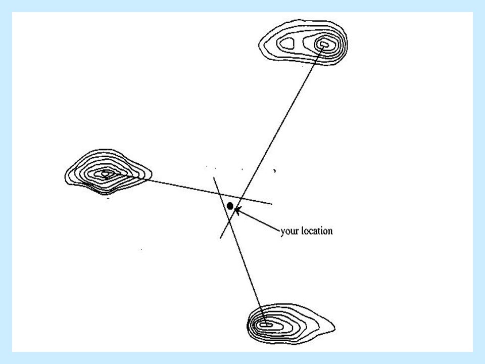
Triangulation: In order to locate yourself on the map by performing Triangulation, the basic idea is to compare your topographic map to what you are looking at, and identify terrain features that you are sure you can both see and associate with a feature on the map.

149
Just by looking at the map and the terrain, you should have a general idea of your location. Terrain recognition is important to pinpoint your location more accurately. Now you determine bearings to these features, and draw lines on the map corresponding to the bearing to those features. The use of at least three lines is recommended, and they should cross in a small triangle.

150
It is ideal to choose landmarks all around you, but sometimes this is not practical, as when on one side of a mountain range, with nothing distinguishable in the other direction. Choose landmarks as far apart as possible. Your best guess at your position will be in the center of the triangle that you draw. This process is illustrated on the next slide.

152
A few points should be made about Triangulation:
First and most obvious, the more points you use, the more accurate you will be able to determine your position. Using more points will also tell if you have a "flyer," i.e. one bearing that you did wrong or terrain feature you misidentified. This line will be way off where the others meet. For these reasons it is preferable to look at as many features as possible.

153
Second, be very careful when using man-made objects
Second, be very careful when using man-made objects. Keep in mind that maps are updated infrequently, and that man-made features usually change more frequently than the terrain features do.

154
Summary: Review: During this block of instruction you have received training on Intersection, Resection and Triangulation.

155
ELO: I Military Terms and Symbols for Map Overlays.

156
Action: Demonstrate the ability to Identify Military terms and symbols on a Map Overlay.
Condition: In a classroom environment, given a block of instruction, Paper and a Writing utensil. Standard: Demonstrate the ability to identify Military terms and symbols on a Map Overlay during the block of instruction.

157
Military Terms and Symbols:
REFERENCE: FM “OPERATIONAL TERMS AND SYMBOLS” CHAPTER 1: OPERATIONAL TERMS AND THEIR DEFINITIONS. THESE ARE LISTED IN ALPHABETICAL SEQUENCE WITH PAGE REFERENCES TO CHAPTERS 2,3,4,5 WHERE THE ACTUAL SYMBOL IS SHOWN. CHAPTER 2: OPERATIONAL ACRONYMS AND ABBREVIATIONS. CHAPTER 3: GRAPHIC CONTROL MEASURES. CHAPTER 4: UNIT SYMBOLS. CHAPTER 5: EQUIPMENT SYMBOLS.

158
Operational Overlay: 1. THE PRIMARY PURPOSE OF THE OVERLAY IS TO REDUCE CONTENT AND ENHANCE THE UNDERSTANDING OF THE WRITTEN OR ORAL ORDER. 2. THE OVERLAY SHOULD BE NEAT AND SIMPLE BUT SHOULD INCLUDE AS MANY CONTROL MEASURES AS POSSIBLE AND ANYTHING ELSE CAN BE DEPICTED GRAPHICALLY.

159
COLORS GRAPHIC CONTROL MEASURES
BLACK: REPRESENTS ALL FRIENDLY CONTROL MEASURES. RED: REPRESENTS ALL ENEMY CONTROL. MEASURE. GREEN: REPRESENTS ALL OBSTACLE BE IT FRIENDLY, ENEMY, NEUTRAL AND FACTIONAL. ANY OTHER COLOR WILL BE SHOWN IN THE LEGEND AND WHAT THEY REPRESENT FM , Ch3

160
COLORS UNIT SYMBOLS

161
BASIC SYMBOLS FRAMES FRIENDLY UNIT SEA OR AIR UNIT HQ ALTERNATE ENEMY
NEUTRAL ENEMY

162
FIELDS

163
UNIT ROLE INDICATOR L INFANTRY AIRBORNE LIGHT ARMORED WHEELED
MECHANIZED INFANTRY AIR ASSAULT

164
UNIT ROLE INDICATOR ANTIARMOR DISMOUNTED MOTORIZED INFANTRY RECON
MECHANIZED INFANTRY DISMOUNTED OBSERVATION POST (LP / OP) MECHANIZED INFANTRY W/GUN SYSTEM
 MECHANIZED. INFANTRY. W/GUN SYSTEM.")
165
UNIT ROLE INDICATOR FIELD ARTILLERY DISMOUNTED TRACKED A M ROTARY WING
ATTACK HELICOPTER MEDIUM LIFT HELICOPTER MEDIUM

166
UNIT ROLE INDICATOR MAINTENANCE MEDICAL SUPPLY PUBLIC AFFAIRS
GUN SYSTEM EQUIPPED SUPPLY TRAINS

167
MP UNIT ROLE INDICATOR ENGINEER MEDICAL TREATMENT FACILITY CHEMICAL
MILITARY POLICE SIGNAL ARTILLERY

168
Size Symbols TEAM SQUAD SECTION PLATOON OR DETACHMENT
COMPANY, BTRY OR TROOP BATTALION OR SQUADRON BRIGADE

169
UNIT SIZE SYMBOLS SQUAD SECTION PLATOON COMPANY BATTERY/TROOP
BATALLION SQUADRON REGIMENT OR GROUP

170
SPECIAL SIZES COMPANY TEAM BATTALION TASK FORCE L
COMPANY TEAM: A TEAM FORMED BY ATTACHMENTOF ONE OR MORE NONORGANIC TANK, MECHANIZED INFANTRY, OR LIGHT INFANTRY PLATOONS TO A TANK, MECHANIZED INFANTRY, OR LIGHT INFANTRY COMPANY EITHER IN EXCHANGE FOR OR IN ADDITION TO ORGANIC PLATOONS. BATTALION TASK FORCE: A FORCE GENERALLY ORGANIZED BY COMBINING TANK AND MECHANIZED INFANTRY ELEMENTS UNDER A SINGLE BATTALION COMMANDER TO CONDUCT SPECIFIC OPERATIONS. A BN. TASK FORCE MAY BE TANK-HEAVY, MECHANIZED INFANTRY-HEAVYOR BALANCED, DEPENDING ON THE CONCEPT AND PLAN OF OPERATION.

171
2nd PLT, A CO, 3rd BN, 1st BDE (Bradley MECH)
")
172
ENEMY INFANTRY COMPANY ARMOR PLATOON CAVALRY RECON

173
ENEMY:

174
WEAPON SYMBOLS LIGHT MG MEDIUM MG 7.62 HEAVY MG 50.CAL LIGHT ANTITANK
GUN MORTAR MEDIUM MORTAR HEAVY MORTAR

175
CONTROL MEASURES (POINTS)
RP 8 PP START POINT RELEASE POINT CHECK POINT PASSAGE POINT 3 ACP CONTACT POINT DECISION POINT COORDINATING POINT AIR CONTROL POINT

176
BOUNDARIES FRIENDLY PLANNED OR ON ORDER FRIENDLY PRESENT

177
BOUNDARIES A A B B 1-11 1-11 2-502 2-502 1 1 2 2

178
LINES FORWARD LINE OF OWN TROOPS FLOT FLOT LIMIT OF ADVANCE LOA LOA
LINE OF CONTACT LC LC

179
LINES LINE OF DEPARTURE LD LD PHASE LINE PL DOG PL DOG
PROBABLE LINE OF DEPLOYMENT PLD PLD

180
AREAS AREA OF OPERATION A 2/1 BATTLE POSITION
DZ=DROP ZONE A 2/1 L EA= ENGAGEMENT AREA BATTLE POSITION PREPARED BUT NOT OCCUPIED LETTER,# OR NAME (P)LETTER,# OR NAME
LETTER,# OR NAME.")
181
AREAS ATTACK ASSAULT ASLT ATK 3 2 KNOWN ENEMY LOCATION ENY (NAME)
")
182
ROUTES FRIENDLY GROUND AXIS OF SUPPORTING
FRIENDLY GROUND AXIS OF MAIN ATTACK

183
DIRECTION OF SUPPORT ATTACK
ATK ROUTES LD DIRECTION OF SUPPORT ATTACK LD FOLLOW AND ASSUME FOLLOW AND SUPPORT

184
ANTITANK UNDER CONSTRUCTION
OBSTACLES WIRE ANTITANK UNDER CONSTRUCTION ANTITANK COMPLETED

185
SCATTERABLE MINEFIELD (AT) WITH SELF DESTRUCT DATE/TIME GROUP
OBSTACLES/MINES Anti- Tank UNSPECIFIED DIRECTIONAL Anti- Personnel S 101200Z SCATTERABLE MINEFIELD (AT) WITH SELF DESTRUCT DATE/TIME GROUP
 WITH SELF DESTRUCT DATE/TIME GROUP.")
186
OBSTACLES/MINES Completed: (Anti-Personnel / Anti-Tank Minefield)
Completed (Unspecified-Minefield) Planned Anti-Tank Minefield Completed: (Anti-Personnel / Anti-Tank Minefield)
 Planned Anti-Tank Minefield. Completed: (Anti-Personnel / Anti-Tank Minefield)")
187
FIRE PLANNING TGT REF POINT LINEAR TARGET NUCLEAR TGT
PAA NUCLEAR TGT AG9998 PAA PAA PAA POSITION AREA FOR ARTILLERY

188
LOCATION CENTER MASS END OF STAFF

189
LOCATIONS

190
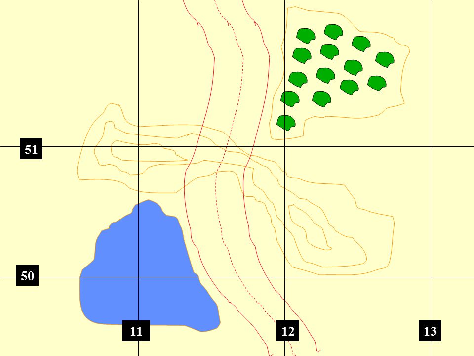
51 50 11 12 13
191
D 51 C 50 11 12 13

192
PRECISE LOCATIONS FM Ch4

193
D C 51 50 11 12 13

194
Check on Learning What does this symbol represent? Infantry
What color represents enemy positions? Red Describe the symbol for friendly Air Assault? 4. What size indicator is this symbol? Squad

195
Summary: Review: During this block of instruction Military symbols and terms for a Map Overlay has been covered.

196
Summary of Course: Review: During this block of instruction you received training on identifying the major terrain features, minor terrain features, colors found on a Military map. In addition, demonstrated the ability to find a point on the map using a protractor, determined the elevation using contour lines and determined distance on a Military Map, demonstrated the ability to use a Lensatic Compass, Basic Land Navigation techniques, Intersection, Resection, Triangulation and Military terms and symbols for a Map Overlay.

197
WHAT ARE YOUR QUESTIONS????

198
You Might be a Soldier If....
1. Your kids recite their ABC's phonetically. 2. Your kids call their sandbox "NTC". 3.Your daughter's first haircut was a flattop. 4.Your kids call the tooth fairy "Slicky Boy". 5.Your son fails the third grade, but tells everyone he was “a phase three recycle". 6.Your two-year old calls everyone in BDUs "daddy". 7.You ruin the movie for everyone around you by pointing out the unrealistic military scenes. 8.You go to a barbecue and insist that your family feed tactically. 9.Your kids show their meal cards at the kitchen door, except the oldest, who is on separate rations, and must pay for the meal. 10.Your wife left you and you held a "Change of Command" ceremony.

199
THE FIVE MOST DANGEROUS THINGS IN THE ARMY:
A Private saying, "I learned this in boot camp...." A Sergeant saying, "Trust me, sir..." A Second Lieutenant saying, "Based on my experience..." A Captain saying, "I was just thinking..." and a Warrant Officer chuckling, "Watch this s**t..." ARE THERE ANY QUESTIONS?

200
Some Sound Advice: 1. If you see a bomb technician running, follow him. 2. Try to look unimportant; they may be low on ammo. 3. When the pin is pulled, Mr. Grenade is not our friend. 4. Incoming fire has the right of way. 5. Mines are equal opportunity weapons. 6. The enemy never watches until you make a mistake. 7. A clean (and dry) set of BDU's is a magnet for mud and rain. 8. If you have a personality conflict with your superior: he has the personality, you have the conflict. 9. The worse the weather, the more you are required to be out in it. 10. No matter which way you have to march, its always uphill.
 set of BDU s is a magnet for mud and rain. 8. If you have a personality conflict with your superior: he has the personality, you have the conflict. 9. The worse the weather, the more you are required to be out in it. 10. No matter which way you have to march, its always uphill.")
Similar presentations


 Blue -hydrography or water features (stream, river, lake, swamp,>")


