Download presentation
Presentation is loading. Please wait.

1
SPACE PRODUCT ASSURANCE
esa Soldering Course based on: EUROPEAN COOPERATION FOR SPACE STANDARDIZATION ECSS-Q-ST-70-18C, 15 November 2008 Preparation, assembly & mounting of RF coaxial cables Part A

2
Change log

3
Introduction The main part of this Standard is based on industrial experience and recommendations from European soldering technology experts. Modifications are incorporated into the text to provide for the specific requirement of low‐outgassing electrical systems which are required by scientific and application satellites. Other additions were made in the light of recent technological advances and results of metallurgical test programmes. The use of processes other than solder assembly is recognized, but only certain general requirements are given in this Standard. These requirements apply to assemblies designed to operate within the temperature limits from ‐45 °C to +85 °C. More extreme temperatures or other unusual environmental applications require special design measures or processing steps to provide environmental survival capability.

4
1 Scope technical requirements and quality assurance provisions for assembly and mounting of high-reliability, radio-frequency (RF) coaxial-cable interconnections for use as transmission lines in spacecraft and associated equipment. these assemblies generally designed for low-loss, stable operation from relatively low frequencies through higher frequencies in the microwave regions these transmission-line cables not to be confused with low- frequency cables with conductive sheaths (usually copper braid), used in applications where shielding of centre conductors from surrounding electrical ambient is required Interconnection of those shielded cables is covered in ECSS-Q-ST-70-08
 coaxial-cable interconnections for use as transmission lines in spacecraft and associated equipment. these assemblies generally designed for low-loss, stable. operation from relatively low frequencies through higher. frequencies in the microwave regions. these transmission-line cables not to be confused with low- frequency cables with conductive sheaths (usually copper braid), used in applications where shielding of centre conductors from surrounding electrical ambient is required. Interconnection of those shielded cables is covered in ECSS-Q-ST")
5
Electromagnetic Spectrum Chart
sonics10kHz ultrasonics 1MHz microwave cut-off frequency for cable 60GHz cut-off frequency for cable 32GHz limit for R125 series sma connectors 18GHz

6
Electromagnetic Spectrum
BANDWIDTH DESCRIPTION FREQUENCY RANGE Extremely Low Frequency (ELF) to 3 kHz Very Low Frequency (VLF) kHz to 30 kHz Radio Navigation & maritime/aeronautical mobile 9 kHz to 540 kHz Low Frequency (LF) kHz to 300 kHz Medium Frequency (MF) kHz to 3000 kHz AM Radio Broadcast kHz to 1630 kHz Travelers Information Service kHz High Frequency (HF) SSB Range MHz to 30 MHz Shortwave Broadcast Radio MHz to 26.1 MHz Very High Frequency (VHF) MHz to 300 MHz Low Band: TV Band 1 - Channels MHz to 88 MHz Mid Band: FM Radio Broadcast VHF Radio Range MHz to 174 MHz High Band: TV Band 2 - Channels MHz to 216 MHz Super Band (mobile/fixed radio & TV) MHz to 600 MHz Ultra-High Frequency (UHF) MHz to 3000 MHz Channels MHz to 806 MHz L-band: MHz to 1500 MHz Personal Communications Services (PCS) MHz to 1990 MHz Unlicensed PCS Devices MHz to 1930 MHz Superhigh Frequencies (SHF) (Microwave) GHz to 30.0 GHz C-band MHz to 7025 MHz X-band: GHz to 8.4 GHz Ku-band GHz to 14.5 GHz Ka-band GHz to 31.0 GHz Extremely High Frequencies (EHF) (Millimeter Wave Signals) GHz to 300 GHz Additional Fixed Satellite GHz to 275 GHz Infrared Radiation GHz to 810 THz Visible Light THz to 1620 THz Ultraviolet Radiation PHz to 30 PHz X-Rays PHz to 30 EHz Gamma Rays EHz to 3000 EHz
 0 to 3 kHz. Very Low Frequency (VLF) 3 kHz to 30 kHz. Radio Navigation & maritime/aeronautical mobile 9 kHz to 540 kHz. Low Frequency (LF) 30 kHz to 300 kHz. Medium Frequency (MF) 300 kHz to 3000 kHz. AM Radio Broadcast 540 kHz to 1630 kHz. Travelers Information Service 1610 kHz. High Frequency (HF) SSB Range 3 MHz to 30 MHz. Shortwave Broadcast Radio 5.95 MHz to 26.1 MHz. Very High Frequency (VHF) 30 MHz to 300 MHz. Low Band: TV Band 1 - Channels MHz to 88 MHz. Mid Band: FM Radio Broadcast VHF Radio Range 88 MHz to 174 MHz. High Band: TV Band 2 - Channels MHz to 216 MHz. Super Band (mobile/fixed radio & TV) 216 MHz to 600 MHz. Ultra-High Frequency (UHF) 300 MHz to 3000 MHz. Channels MHz to 806 MHz. L-band: 500 MHz to 1500 MHz. Personal Communications Services (PCS) 1850 MHz to 1990 MHz. Unlicensed PCS Devices 1910 MHz to 1930 MHz. Superhigh Frequencies (SHF) (Microwave) 3 GHz to 30.0 GHz. C-band 3600 MHz to 7025 MHz. X-band: 7.25 GHz to 8.4 GHz. Ku-band 10.7 GHz to 14.5 GHz. Ka-band 17.3 GHz to 31.0 GHz. Extremely High Frequencies (EHF) (Millimeter Wave Signals) 30.0 GHz to 300 GHz. Additional Fixed Satellite 38.6 GHz to 275 GHz. Infrared Radiation 300 GHz to 810 THz. Visible Light 810 THz to 1620 THz. Ultraviolet Radiation 1.62 PHz to 30 PHz. X-Rays 30 PHz to 30 EHz. Gamma Rays 30 EHz to 3000 EHz.")
7
2 Normative references ECSS‐S‐ST‐00‐01 ECSS system — Glossary of terms
ECSS‐Q‐ST‐10‐09 Nonconformance control ECSS‐Q‐ST‐20 Quality assurance ECSS‐Q‐ST‐60 EEE components ECSS‐Q‐ST‐70‐02 Thermal vacuum outgassing test for the screening of space materials ECSS‐Q‐ST‐70‐08 Manual soldering of high‐reliability electrical connections ECSS‐Q‐ST‐70‐26 Crimping of high‐reliability electrical connections ECSS‐Q‐ST‐70‐28 Repair and modification of printed circuit board assemblies MIL‐C‐17G(3) SUP1 General specification for cables, radio frequency, flexible and semi‐rigid. (8 Jan 1996)
 SUP1 General specification for cables, radio frequency, flexible and semi‐rigid. (8 Jan 1996)")
8
3 Terms, definitions and abbreviated terms
3.1 Terms from other standards For the purpose of this Standard, the terms and definitions from ECSS‐S‐ST‐00‐01 apply, in particular for the following term: requirement 3.2 Terms specific to the present standard 3.2.1 minimum bend radius inside radius of the bend measured on the outer surface of the cable

9
3 Terms, definitions and abbreviated terms
For the purpose of this Standard, the abbreviated terms from ECSS‐S‐ST‐00‐01 and the following apply: Abbreviation Meaning FEP fluorinated ethylene propylene PTFE polytetrafluoroethylene SMA sub miniature version A VSWR voltage standing wave ratio

10
4 Principles and prerequisites of reliable soldered or crimped cable connections
4.1 Principles of reliable soldered or crimped semi-rigid cable connections Reliable soldered or crimped connections result from proper design, control of tools, materials and work environments and careful workmanship

11
4 Principles and prerequisites of reliable soldered or crimped cable connections
4.1 Principles of reliable soldered or crimped semi-rigid cable connections (continued) Basic design concepts for reliable connections and which prevent joint failure: a. Avoidance of dimensional mismatch between coaxial-cable assembly and units being connected; i.e. not forcing the semi-rigid cable assembly into position and thereby cracking or pre-stressing joints b. Use of cable-end connectors with retractable (non-captive) coupling nuts; after completion of mounting, the coaxial-cable assembly is not in a state of tension resulting from axial movement when connectors are threaded together
 Basic design concepts for reliable connections and. which prevent joint failure: a. Avoidance of dimensional mismatch between coaxial-cable assembly and units being connected; i.e. not forcing the semi-rigid cable assembly into position and thereby cracking or pre-stressing joints. b. Use of cable-end connectors with retractable (non-captive) coupling nuts; after completion of mounting, the coaxial-cable assembly is not in a state of tension resulting from axial movement when connectors are threaded together.")
12
4 Principles and prerequisites of reliable soldered or crimped cable connections
4.1 Principles of reliable soldered or crimped semi-rigid cable connections (continued) c. Minimizing internal stresses on soldered or crimped connections resulting from exposure to thermal cycling NOTE thermal coefficient of expansion of the dielectric is about 10 times that of copper and in service this can introduce a tensile stress on the joint d. The various assembly and mounting processes are covered by quality-control inspection steps.
 c. Minimizing internal stresses on soldered or crimped connections resulting from exposure to thermal cycling. NOTE thermal coefficient of expansion of the dielectric is. about 10 times that of copper and in service this can introduce a tensile stress on the joint. d. The various assembly and mounting processes are covered by quality-control inspection steps.")
13
4 Principles and prerequisites of reliable soldered or crimped cable connections
4.2 Prerequisites for assembly and mounting of semi-rigid coaxial cables documented soldering or crimping programmes: procedures for training, certification, maintenance of certified status recertification and revocation of certified status for soldering, crimping and inspection personnel workmanship standards consisting of satisfactory work samples or visual aids illustrating quality characteristics for all connections involved, including applicable illustrations in annex B of this Standard

14
4 Principles and prerequisites of reliable soldered or crimped cable connections
4.2 Prerequisites for assembly and mounting of semi-rigid coaxial cables Records kept to provide identification between finished product and operator. Records also maintained of training, testing and certification status of assembly operators. Records retained for at least one year, or longer if this is specific requirement of the customer’s project Equipment and tools verified and calibrated periodically for proper operation, and records of tool calibration and verification maintained (see clause 5.8).
.")
15
4 Principles and prerequisites of reliable soldered or crimped cable connections
4.2 Prerequisites for assembly and mounting of semi-rigid coaxial cables (continued) For soldering or crimping requirements not covered in this Standard, the contractor submits a process procedure including all pertinent quality requirements to customer’s project office for approval in accordance with ECSS-Q-ST-70.
 For soldering or crimping requirements not covered in this Standard, the contractor submits a process procedure including all pertinent quality requirements to customer’s project office for approval in accordance with ECSS-Q-ST-70.")
16
4 Principles and prerequisites of reliable soldered or crimped cable connections
4.3 Alternative coaxial cable technologies Alternative coaxial cable technologies are accepted for application in individual customer programmes following the completion of qualification and batch acceptance test programmes in accordance with 5.7. The precise test-programme and results are subject to review and acceptance by the relevant customer programme For materials used in the alternative technology see ECSS-Q-ST-70-71 Some mounting requirements for alternative technologies are given in 5.6.3

17
5 Requirements 5.1 Preparatory conditions 5.1.1 Facility cleanliness
a. Unless classified as a cleanroom, areas in which soldering is carried out shall be maintained in neat orderly fashion with no loose material (dirt, dust, solder particles, oils and clipped wires) that can cause contamination of the soldered connection. Furniture kept to minimum in work areas and be arranged to allow easy and thorough cleaning of the floor c. A washroom and eating, drinking and smoking facilities should be located close to, but outside, the soldering areas.
 that can cause contamination of the. soldered connection. Furniture kept to minimum in work areas and be. arranged to allow easy and thorough cleaning of the floor. c. A washroom and eating, drinking and smoking facilities should be located close to, but outside, the soldering areas.")
18
5 Requirements 5.1.1 Facility cleanliness (continued)
d. Working surfaces covered with an easily cleaned hard top or have a replaceable surface of clean, non- corrosive silicone-free paper. e. Clean tools in the soldering operation f. excess lubricants removed before soldering starts. g. Before assembly, wire, terminal and connector contacts visually examined for cleanliness, absence of oil films and freedom from tarnish or corrosion.

19
5 Requirements 5.1.2 Environmental conditions
a. controlled environment that limits entry of contamination b. room temperature: 22 ± 3 ºC relative humidity at room temperature 55 ± 10 % c. work stations not be exposed to draughts fresh air supplied to the room through filtering system; positive pressure with respect to adjacent rooms.

20
5 Requirements 5.1.3 Lighting requirements a. lighting intensity minimum of lux on work surface b. at least 90 % of the work area shall be shadowless and without severe reflections

21
5.1.4 Equipment and tools 5 Requirements 5.1.4.1 Brushes
a. The supplier shall use brushes for cleaning, provided that they do not scratch the metal surface to be cleaned or damage adjacent materials beyond their visual inspection requirements. NOTE Medium‐stiff natural‐ or synthetic‐bristle brushes can be used. b. The supplier shall clean these brushes before use in a solvent prescribed in clause c. The supplier shall not use wire brushes.

22
5.1.4.1 Equipment and tools (continued)
5 Requirements Equipment and tools (continued) 5.4.2 Files a. The supplier shall use smooth, single cut and mill type files for dressing copper soldering‐iron tips and removing burrs from the conductor. b. The supplier shall not use files on surface‐treated tips or pretinned items. NOTE Nickel plated is an example for surface‐treatment. c. The supplier shall keep the files in a good condition and shall be cleaned before use. d. The supplier shall not keep the files in a cleanroom environment.
 Files. a. The supplier shall use smooth, single cut and mill type files for dressing copper soldering‐iron tips and removing burrs from the conductor. b. The supplier shall not use files on surface‐treated tips or pretinned items. NOTE Nickel plated is an example for surface‐treatment. c. The supplier shall keep the files in a good condition and shall be cleaned before use. d. The supplier shall not keep the files in a cleanroom environment.")
23
5 Requirements 5.1.4.3 Cutting tools
a. Cutting tools for preparation of the semi-rigid cable: Fine-tooth jeweller’s saws (0,28 mm - 0,33 mm blade preferred) razor blades (single edged) suitable wire cutters. b. The jeweller’s saw shall be used together with a cable clamping device; see Figure C-1.
 razor blades (single edged) suitable wire cutters. b. The jeweller’s saw shall be used together with a cable clamping. device; see Figure C-1.")
24
5 Requirements 5.1.4.3 Cutting tools (continued)
c. The supplier shall cut the dielectric and inner conductor with a tool that produces a clean, smooth‐cut surface along the entire cutting edge. d. The supplier shall not perform any twisting action during this cutting operation.

25
5 Requirements 5.1.4.4 Cable-forming tools
Bending jigs (Figure C-2) available to form cable to predetermined shapes as identified by the contractor’s engineering drawing Roller sizes to be available for each cable diameter. Equipment not to introduce dents, nicks, wrinkles or cracks in cable outer conductor.
 available to form cable to predetermined. shapes as identified by the contractor’s engineering drawing. Roller sizes to be available for each cable diameter. Equipment not to introduce dents, nicks, wrinkles or cracks. in cable outer conductor.")
26
5 Requirements 5.1.4.5 Cable stripping and dressing tools
a. The supplier shall use cable stripping and dressing tools in such a way that they do not twist, ring, nick, or score the underlying material surface. NOTE Many pieces of commercially available equipment exist to strip the outer conductor or the dielectric material. These can be automatic, power‐driven devices with precision factory‐set non‐adjustable cutting and stripping dies, or precision hand‐type strippers with accurately machined cutting heads. b. The supplier shall perform either periodic calibration or sample evaluation during a production run.

27
5 Requirements 5.1.4.6 Heat-treatment chamber
a. The supplier shall use thermal cycling cabinets, ovens, refrigeration units or cold chambers capable of maintaining temperatures between ‐50 °C and +90 °C NOTE Under certain circumstances (see Table 5‐2 step 3.3) greater temperature extremes can be required. b. The supplier shall calibrate the working zone to within ±5 °C.
 greater temperature extremes can be required. b. The supplier shall calibrate the working zone to within ±5 °C.")
28
5 Requirements 5.1.4.7 Soldering equipment
a. The supplier shall accomplish one of the following soldering methods that conforms to the requirements on “Equipment and tools” of ECSS‐Q‐ST‐70‐08: 1. by hand or 2. by using a resistance heating unit or 3. other contact heat source * * eg thermal resistance tweezers, solder pot

29
5 Requirements 5.1.4.7 Soldering equipment
b. When non‐contact heat sources are utilized, the supplier shall set up, operate and demonstrate to the satisfaction of the customer that the particular method and schedule produces joints of an acceptable standard. NOTE This includes verification testing as detailed in clause 5.7.

30
5 Requirements 5.1.4.8 Crimping equipment
a. The supplier shall use the settings recommended by the tool manufacturer as a guide. NOTE This is necessary since manual crimping tools are available; they are custom designed and applicable only for particular connector shells. b. The supplier shall set up the tool for the cable and connector types by a detailed calibration programme based on the requirements of ECSS‐Q‐ST‐70‐26. c. The supplier shall perform verification testing as detailed in clause 5.7.

31
5.1.4.9 Assembly equipment, tools and processes for other technologies
5 Requirements Assembly equipment, tools and processes for other technologies a. The supplier shall only use the equipment, tools, and processes for the assembly of the cables and connectors that are designed to avoid damage or degradation of the cables and connectors. NOTE The equipment, tools, and processes can be subject to a manufacturing audit by the customer before application in their programme.

32
5.1.4.10 Defective or uncalibrated equipment or tools
5 Requirements Defective or uncalibrated equipment or tools The supplier shall promptly remove and replace defective or uncalibrated equipment or tools from the work areas.

33
Equipment and tools Sourcing hints:
Specialist RF cable assembly tooling such as Radiall: R SMA Solder kit (~£3107 in 2007) Radiall: R Bending kit, (~£550 in 2007) Radiall Technical support Barry Wheeler tel Availability & pricing from: Microtek Components tel also: Richardson Electronics Pte Ltd Tel: Fax: Kaylene Chong
 Radiall: R Bending kit, (~£550 in 2007) Radiall Technical support Barry Wheeler. tel Availability & pricing from: Microtek Components tel also: Richardson Electronics Pte Ltd. Tel: Fax: Kaylene Chong")
34
Equipment and tools Radiall SMA solder kit

35
Equipment and tools Radiall bending kit

36
Equipment and tools Radiall coning kit
ie to form point on centre conductor for connectors without centre contact.

37
Sourcing hints: Equipment and tools
Specialist RF cable assembly tooling such as ie forming point on centre conductor for connectors without centre contact.

38
Sourcing hints: Equipment and tools
Specialist RF connector gauge kits from Maury Microwave

39
Sourcing hints: Equipment and tools
Specialist RF connector gauge kits from SRI Connector Gage Co.

40
Equipment and tools More sourcing hints:
Suhner cable cutting device type 9144. Triton PTH (press to heat) light duty soldering tool American Beauty Tools (Jim Steadie) Pace thermal tweezers (2V, 80-W) (obsolete tool)
 light duty soldering tool American Beauty cat=handpieces#10517 Welwyn Tools (Jim Steadie) Pace thermal tweezers (2V, 80-W) (obsolete tool)")
41
5.2 Material selection 5.2.1 Solder
a. The supplier shall use solder ribbon, wire and preforms, provided that the alloy and flux conform to the requirements on “material selection” of ECSS‐Q‐ST‐70‐08. NOTE 1 The following solder alloys are approved: • 60 Sn (remainder lead): For degolding operations, coating and pretinning. 96 Sn (remainder silver): For making coaxial‐cable outer‐conductor‐to connector solder joint. 96 Sn or 63 Sn (remainder lead): For contact‐pin soldering and cover soldering of right angle connectors. NOTE 2 Refer also to the table of “Chemical composition of spacecraft solders” in ECSS‐Q‐ST‐70‐08.
: For degolding operations, coating and pretinning. 96 Sn (remainder silver): For making coaxial‐cable. outer‐conductor‐to connector solder joint. 96 Sn or 63 Sn (remainder lead): For contact‐pin. soldering and cover soldering of right angle. connectors. NOTE 2 Refer also to the table of Chemical composition of spacecraft solders in ECSS‐Q‐ST‐70‐08.")
42
ECSS-Q-ST-70-08: Solder Composition

43
5.2 Material selection 5.2.2 Flux
The supplier should perform degolding and pretinning operations with activated fluxes. NOTE Examples of activated fluxes are J‐STD‐004 Type ROL1 and ROH1. b. The supplier shall completely remove activated fluxes immediately after use and before any further soldering operation. c. The supplier shall only use pure rosin flux for spacecraft assembly work. NOTE An example of pure rosin flux is J‐STD‐004 Type ROL0.

44
Solder theory: Intermetallics
Cu3Sn Cu6Sn5 Au AuSn AuSn2 Data source: September 2001 presentation by Istituto Italiano della Saldatura (LM)
")
45
Solder Theory: TIN-LEAD PHASE DIAGRAM
PURE LEAD MP 327º PURE TIN MP 232º pasty pasty 183º Eutectic 61.9% Sn 38.1% Pb solid

46
Eutectic Tin/Lead Solder
Composition of Eutectic Tin/Lead Solder + Pb (Lead) 37% 327°C Sn/Pb 63/37 183°c Sn (Tin) 63% 232°C
 37% 327°C. Sn/Pb. 63/ °c. Sn (Tin) 63% 232°C.")
47
(Eutectic means lowest melting point, no melting range)
Eutectic Sn/Pb (Eutectic means lowest melting point, no melting range) 183°C Solid Liquid Sn63/Pb37 is near eutectic and recommended for pcb soldering For solder-pot processes, the amount of Sn in excess of 61.9% allows for Sn depletion during use. Sn61.9/Pb38.1 is true eutectic
 183°C. Solid. Liquid. Sn63/Pb37 is near eutectic and recommended for pcb soldering. For solder-pot processes, the amount of Sn in excess of 61.9% allows for Sn depletion during use. Sn61.9/Pb38.1 is true eutectic.")
48
TIN-SILVER PHASE DIAGRAM
Solder Theory: TIN-SILVER PHASE DIAGRAM TIN-SILVER PHASE DIAGRAM PURE SILVER MP 962ºC Eutectic 96% Sn 4% Ag PURE TIN MP 232ºC 221º solid

49
Flux Flux Cored Solder

50
Wetting Action and Contamination
Oxide film (contaminant) prevents wetting and the formation of the INTERMETALLIC LAYER. Flux removes this oxide film. INTERMETALLIC LAYER SOLDER COPPER
 prevents wetting and the formation of the INTERMETALLIC LAYER. Flux removes this oxide film. INTERMETALLIC LAYER. SOLDER. COPPER.")
51
TIP TEMPERATURE MASS OF TIP MASS OF WORK IRON POWER (Wattage) SURFACES
THERMAL LINKAGE (solder bridge)
")
52
Slow Temperature Rise RF cable SOLDERING IRON connector body

53
Fast Temperature Rise RF Cable SOLDERING IRON Connector body
A TIP WHICH IS TOO LARGE CAN ‘PULL’ THE FILLET INTO AN ASYMETRICAL SHAPE AS THE TIP IS WITHDRAWN

54
Correct Match RF Cable SOLDERING IRON Connector body

55
No Thermal (solder) Bridge
RF Cable SOLDERING IRON Connector body SLOW HEAT TRANSFER LONGER DWELL TIME

56
Thermal (solder) Bridge
FASTER HEAT TRANSFER RF Cable Connector body

57
5.2 Material selection 5.2.3 Solvents
The supplier shall only use solvents for the removal of grease, oil, dirt, flux and flux residues that are non-conductive and non-corrosive. dirt, flux and flux residues that do not dissolve or degrade the quality of parts or materials or remove their identification markings. The supplier shall label the solvents and maintain them in a clean and uncontaminated condition. The supplier shall not use solvents showing evidence of contamination or decomposition. e. The supplier shall not use solvents that transfer dissolved flux residue onto contact surfaces. NOTE This can be the case for switches, potentiometers or connectors. f. The supplier shall use solvents in conformance with ECSS‐Q‐ST‐70‐08, clause 6.4h.

58
5.2 Material selection 5.2.3 Solvents (continued)
Extract from ECSS-Q-ST-70-08, clause 6.4h:

59
5.2 Material selection 5.2.4 Cable selection
The supplier shall procure semi‐rigid cables in conformance with the detailed requirements of MIL‐C‐17G(3) SUP1. NOTE The selection of a particular coaxial cable Involves consideration of the specific electrical, mechanical and environmental requirements of the project.
 SUP1. NOTE The selection of a particular coaxial cable. Involves consideration of the specific electrical, mechanical and environmental requirements of the. project.")
60
5.2 Material selection 5.2.4 Cable selection (continued)
b. The supplier shall procure semi‐rigid cable with outer conductor diameter standardized as either 0,085 inches or 0,141 inches (±0,001 inches) and fabricated from copper. NOTE The outer conductor can be finished with silver plating. RG ” RG ” 0,141 ” semi rigid cable: MIL M17 / 130-RG402 0,085” semi rigid cable: MIL M17 / 133-RG405
 and. fabricated from copper. NOTE The outer conductor can be finished with. silver plating. RG RG ,141 semi rigid cable: MIL M17 / 130-RG402. 0,085 semi rigid cable: MIL M17 / 133-RG405.")
61
5.2 Material selection SPC = Silver-plated copper
SPCW = Silver-plated copper-clad steel wire

62
5.2 Material selection 5.2.4 Cable selection (continued)
c. The supplier shall procure semi‐rigid cable with dielectric material composed of polytetrafluoroethylene (PTFE) or fluorinated ethylene propylene (FEP). d. The supplier shall select the material composition of the inner conductor following a review of the specific project/equipment requirements. NOTE 1 The review also considers the proposed connector designs. NOTE 2 In general copper is a suitable inner conductor. 62 62
 or fluorinated. ethylene propylene (FEP). d. The supplier shall select the material composition. of the inner conductor following a review of the. specific project/equipment requirements. NOTE 1 The review also considers the proposed. connector designs. NOTE 2 In general copper is a suitable inner. conductor")
63
Cable specs 63 63

64
5.2 Material selection 5.2.5 Connector selection
The supplier shall only select approved connectors in conformance with the requirements on “Quality levels” of ECSS-Q-ST-60, for use in assembling solder-type semi-rigid cables. b. The supplier may use connectors with the form of: straight cable-end connector, with a centre contact, and non- captive coupling nut; NOTE See Figure C-3 for distinction between non-captive and captive coupling nut connectors. 2. right angle cable-end connector. 3. flange‐mount male receptacle, either two- or four-hole type. c. The use of right angle cable-end connector shall be restricted to applications where stress-free mounting of cables with these captive nut connectors can be assured. d. For other applications the use of right angle cable-end connector should be minimized. 64 64

65
Figure C-3: Approved and non-approved straight solder-type cable-end connectors
65 65

66
5.2 Material selection 5.2.5 Connector selection (continued)
e. All non‐metallic materials incorporated in the connector shall meet the outgassing requirements according to ECSS‐Q‐ST‐70‐02. f. The supplier shall not use pure tin or cadmium finishes. g. For the use of special connectors for non‐solder systems, the supplier shall obtain customer approval. 66 66

67
5.2 Material selection 5.2.5 Connector selection (continued)
Supplementary notes concerning Radiall connectors: R124XXX XXX: Commercial for DC – 6GHz R125XXX XXX: Standard for DC – 18GHz (other options to 27GHz) R126XXX XXX: Space Qualified; similar performance to Standard but with beryllium-copper body and centre contact 67 67
 R126XXX XXX: Space Qualified; similar performance. to Standard but with beryllium-copper body and centre. contact")
68
5.2 Material selection 5.2.5 Connector selection (continued)
Link to Radiall search result (example r ): Link to Radiall Product datasheet & Assembly instructions: 68 68
: Link to Radiall Product datasheet & Assembly instructions: dsn=dmsDS&action=datasheet&object=")
69
Connector data (from http://www.wa1mba.org/rfconn.htm)
Return Loss of Johnson Components Field Replaceable SMA connector. Mounted on a chassis, not a cable. Return loss bumps at 12.4, 18, and 26.5 GHz are indications of SMA geometric constraints that have led to those specific frequency limitations in some SMA connectors. 69 69

70
Connector data (from http://www.wa1mba.org/rfconn.htm)
70 3.5 mm and SMA mating SWR 70

71
Connector data (from http://www.vitelec.co.uk/)
Plating very important at microwave frequencies because of skin effect. At very high frequencies, signals do not penetrate far into the conductors, power and current flow in metals is essentially on the surface, or “skin”, of the conductors. We take advantage of this by plating a fairly good conductor with several skin depths of an excellent conductor. Thus, the electrical properties of the excellent conductor are obtained with minimum cost. Skin effect pronounced at high frequencies and usually not a concern below a few GHz. The following table shows relative properties of several common connector platings and base metals. Electrical conductivity shown is relative to brass. eg Silver is 2.4x better while Stainless Steel is 20x worse than brass. 71 71

72
Other causes of high VSWR and Insertion Loss
air gap poor solder fill (<70%) beween contact and centre conductor Insertion loss: crushed cable bend radius too tight 72 72
 beween contact and centre conductor. Insertion loss: crushed cable. bend radius too tight")
73
Connector data (from http://www.vitelec.co.uk/)
73 73

74
Connector data (from MIL-DTL Radio Frequency Connectors APPLICATION NOTES 1) Plug coupling nuts and cable nut mounted connectors may have silicone rubber O-Ring seals which are an outgassing concern. Connectors may require additional processing for outgassing control. This should include a bake of the connector and removal or replacement of the silicone rubber O-Rings with fluorosilicone O-Rings which meet outgassing requirements. 2) Temperature range for flexible and semirigid connectors is -65°C to +165°C. Temperature range for PC mounted connectors is -65°C to +105°C. 3) The use of safety wire is recommended to secure mated connectors together. 4) B designated connectors which require special tooling for assembly are considered non-field replaceable and are not preferred. Most are inactive for new design. 5) Only series SMA connectors are recommended for satellite use in lower earth orbits. Series N and TNC connectors are not recommended for use in lower earth orbits due to atomic oxygen corrosion concerns of their silver plating. 74 74
 Plug coupling nuts and cable nut mounted connectors may have silicone rubber. O-Ring seals which are an outgassing concern. Connectors may require additional. processing for outgassing control. This should include a bake of the connector and. removal or replacement of the silicone rubber O-Rings with fluorosilicone O-Rings. which meet outgassing requirements. 2) Temperature range for flexible and semirigid connectors is -65°C to +165°C. Temperature range for PC mounted connectors is -65°C to +105°C. 3) The use of safety wire is recommended to secure mated connectors together. 4) B designated connectors which require special tooling for assembly are considered. non-field replaceable and are not preferred. Most are inactive for new design. 5) Only series SMA connectors are recommended for satellite use in lower earth. orbits. Series N and TNC connectors are not recommended for use in lower earth. orbits due to atomic oxygen corrosion concerns of their silver plating")
75
Radiall products http://www.radiall.com/main.php
• ESA Qualified Part List ( QPL ): More than 400 part numbers under : • ESA SCC 3402/001 • ESA SCC 3402/002 • ESA/SCC 3402/003 • SMA connectors under : • ESA SCC 3402 • RADIALL RAD C 2612 • Customer requirements 75
: More than 400 part numbers under : • ESA SCC 3402/001. • ESA SCC 3402/002. • ESA/SCC 3402/003. • SMA connectors under : • ESA SCC • RADIALL RAD C • Customer requirements. 75.")
76
Components, reference sources:
Waveguides: 76 76

77
5.2 Material Selection 5.2.5 Connector selection (continued)
Supplementary notes concerning degolding: fine solder braid (for degolding inside connector body) and 22AWG (19 x 0.15) stranded wire (for degolding inside centre contact) 77 77
 and. 22AWG (19 x 0.15) stranded wire. (for degolding inside centre contact)")
78
5.3 Preparation of semi-rigid cable
5.3.1 General coaxial cables shall be supplied in the form of straight lengths NOTE initial preparation is similar for each cable diameter and each connector type, whether joining by soldering or crimping 78 78

79
5.3 Preparation of semi-rigid cable
5.3.2 Inspection of cable delivered cable shall be removed from container and inspected for dents, nicks, wrinkles, blisters and contamination b) above are cause for rejection 79 79
 above are cause for rejection")
80
5.3 Preparation of semi-rigid cable
5.3.3 Cutting cable to initial oversize length total required length of the cable calculated from engineering drawing taking account of bends and angles b) additional length of approximately 10 mm is added to allow for bending, preconditioning and end dressing. c) cable held in special fixture, eg Figure 1, and cut to “initial length” using fine-toothed jeweller’s saw d) don’t overtighten the special fixture, as this can damage the cable e) cut end shall be deburred and examined. 80 80
 additional length of approximately 10 mm. is added to allow for bending, preconditioning and. end dressing. c) cable held in special fixture, eg Figure 1, and cut. to initial length using fine-toothed jeweller’s saw. d) don’t overtighten the special fixture, as this can. damage the cable. e) cut end shall be deburred and examined")
81
5.3 Preparation of semi-rigid cable
5.3.4 Cable forming and minimum bend radius a) cables shall be formed to required shape dimensions before cable preconditioning NOTE suitable jig (see Figure C2) shall be provided b) only one bending operation shall be performed to form each shape c) no attempt shall be made to reshape a bent cable 81 81
 cables shall be formed to required shape. dimensions before cable preconditioning. NOTE suitable jig (see Figure C2) shall be provided. b) only one bending operation shall be performed. to form each shape. c) no attempt shall be made to reshape a bent cable")
82
5.3 Preparation of semi-rigid cable
5.3.4 Cable forming and minimum bend radius (continued) d) design rules shall establish minimum bend radii as in Table 5-1 inside radius of bend measured on outer surface of cable Table 5-1: Design rules for minimum bend radius 82 82
 d) design rules shall establish minimum bend radii as in. Table 5-1. inside radius of bend measured on outer surface. of cable. Table 5-1: Design rules for minimum bend radius")
83
5.3 Preparation of semi-rigid cable
5.3.4 Cable forming and minimum bend radius (continued) e) Each finished cable end shall have a minimum straight length of cable to allow for clearance during the assembly and mounting operations f) The straight length shall be greater than 10 mm for 0,085 diameter cable g) The straight length shall be greater than 20 mm for 0,141 h) Prevent wrinkling or cracking i) Bending of the cable shall be by applying slow, even, continuous pressure 83 83
 e) Each finished cable end shall have a minimum straight length of. cable to allow for clearance during the assembly and mounting. operations. f) The straight length shall be greater than 10 mm for 0,085. diameter cable. g) The straight length shall be greater than 20 mm for 0,141. h) Prevent wrinkling or cracking. i) Bending of the cable shall be by applying slow, even, continuous. pressure")
84
5.3 Preparation of semi-rigid cable
5.3.5 Preconditioning heat treatment General The supplier shall achieve core stress relief by preconditioning each cable before it becomes a cable assembly. 84 84

85
5.3 Preparation of semi-rigid cable
NOTE The electrical and mechanical performances specified for semi‐rigid cables are achieved by a compression fit between the outer conductor and the dielectric core, which, in turn, necessitates manufacturing processes that cause deformation of the core by compression and elongation. The resulting stress that is initially non‐uniform tends to equalize by cold flow within a few weeks after the manufacturing and causes withdrawal of the core into the cable. If this occurs in cable that has become part of a cable assembly, the resulting development of an air‐gap at the cable/connector interface causes an increase in the voltage standing wave ratio (VSWR). Therefore the preconditioning is performed. 85 85
. Therefore the preconditioning is performed")
86
5.3 Preparation of semi-rigid cable
5.3.5 Preconditioning heat treatment (continued) Heat treatment process The supplier shall perform preconditioning in conformance with Table 5-2 on cables that are formed into the required bend configuration. b. The supplier shall not perform preconditioning on a soldered or crimped cable. NOTE This is valid even if only one lead end is terminated to a connector. c. The supplier shall place the entire cable in the thermal cycling arrangement. d. The rate of change of temperature shall not exceed 2 °C per minute. NOTE Recommendations for dealing with special requirements (e.g. higher operating temperature extremes) can be obtained from cable manufacturers. 86 86
 Heat treatment process. The supplier shall perform preconditioning in conformance with Table 5-2. on cables that are formed into the required bend configuration. b. The supplier shall not perform preconditioning on a soldered or crimped cable. NOTE This is valid even if only one lead end is terminated to a connector. c. The supplier shall place the entire cable in the thermal cycling. arrangement. d. The rate of change of temperature shall not exceed 2 °C per. minute. NOTE Recommendations for dealing with special requirements (e.g. higher operating temperature extremes) can be obtained from. cable manufacturers")
87
Thermal Coefficient of Expansion (CTE)
Typical CTE Values in Electronics: glass or ceramic => ppm/°C FR4 x-y axis => ppm/°C FR4 z axis => 180ppm/°C Polyimide-glass x-y axis => ppm/°C Polyimide-glass z axis => ppm/°C Copper => ppm/°C Aluminium => ppm/°C Solder (Sn60) => ppm/°C Dielectric, polytetrafluoroethylene (PTFE) or fluorinated ethylene propylene (FEP) => approx 160 ppm/degC Need for Stress Relief to accommodate differential expansion across 135deg DT (full sun to earth shadow) Or…. 300deg DT (room temp to soldering temp) 87
 => 25 ppm/°C. Dielectric, polytetrafluoroethylene (PTFE) or fluorinated ethylene propylene (FEP) => approx 160 ppm/degC. Need for Stress Relief to accommodate differential expansion. across 135deg DT (full sun to earth shadow) Or…. 300deg DT (room temp to soldering temp) 87.")
88
Table 5-2: Preconditioning heat treatment process
88 88

89
Thermal Cycling (Preconditioning) Requirements
Ramp rate not to exceed 2ºC/minute Dwell times = 1 hour Temperature range ºC Minimum 3 complete cycles 89

90
Thermal Cycling (Preconditioning) Requirements
Thermal Cycling (Preconditioning) Requirements Step Preconditioning Action Time ( h ) 1 2 3 4 5 6 7 8 Cool from +25°C to –45°C * -45°C for 1 hour Return to ambient (+25°C) ambient for 1 our Heat from +25°C to +85°C * +85°C Return to ambient * ambient for 1 hour Measure dielectric protrusion / trim flush * max rate of change = 2°C/min 0:35 1:00 0:30 Single cycle duration: 6:10 2nd cycle, as above 3rd cycle, as above 6.10 Stabilising soak of (24-1) hours 23:00 Minimum Total duration: 41:30 90
 Requirements. Step. Preconditioning Action. Time ( h ) Cool from +25°C to –45°C * -45°C for 1 hour. Return to ambient (+25°C) ambient for 1 our. Heat from +25°C to +85°C * +85°C. Return to ambient * ambient for 1 hour. Measure dielectric protrusion / trim flush. * max rate of change = 2°C/min. 0:35. 1:00. 0:30. Single cycle duration: 6:10. 2nd cycle, as above. 3rd cycle, as above Stabilising soak of (24-1) hours. 23:00. Minimum Total duration: 41:")
91
5.3 Preparation of semi-rigid cable
5.3.6 Trimming cable to final length After the preconditioning, the supplier shall adjust the cable form to the tolerance of the engineering drawing. b. The supplier shall cut the cable to size such that when it is assembled it fits with minimum stress. c. The supplier shall perform cutting in conformance with the directions given in clause 91 91

92
5.3 Preparation of semi-rigid cable
5.3.7 Stripping the cable ends The supplier shall use milling tools for stripping the cable ends. NOTE See also clause b. For each stripping operation, the supplier shall follow written instructions. NOTE This allows a reproducible process that does not damage the conductor surfaces. c. The supplier shall regularly change cutting and milling blades. d. The supplier shall remove burrs. 92 92

93
Removing Outer Sheath Using Radiall tools, fit cable into trimming tool & collett, items 55 & 58. Trim with jeweller’s saw, 0.33mm blade to achieve 3.17 ± .005mm trim length. Carefully trim dielectric with a single-edged razor blade. The outer sheath and dielectric should now be removed using a rotating motion as shown in the drawing below. 93

94
5.3 Preparation of semi-rigid cable
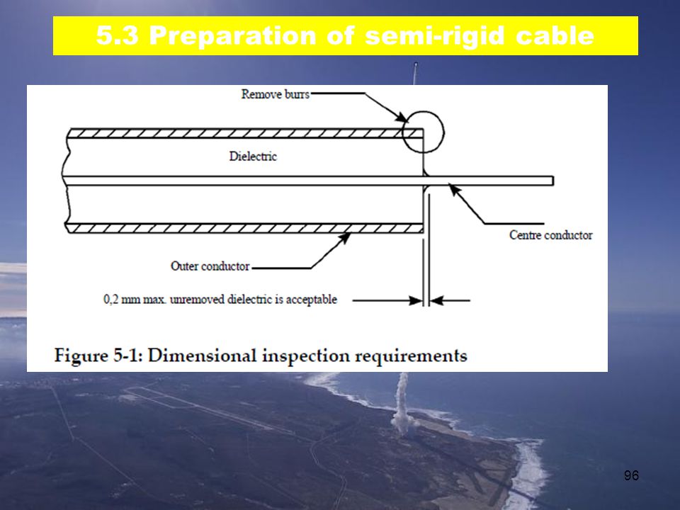
5.3.8 Inspection of stripped cable ends For each of the stripped ends, the supplier shall perform a quality control inspection checking the following criteria: no metal or foreign particles are on the face of the dielectric. 2. the outer conductor contains no burrs or major surface defects and is flush with the dielectric. 3. unremoved dielectric near the centre conductor does not exceed 0,2 mm. 94 94

95
5.3 Preparation of semi-rigid cable
5.3.8 Inspection of stripped cable ends b. The supplier shall specify the length of the wire inner conductor. NOTE This is necessary since the length is dependent on the connector type. c. The supplier shall report measurements of the external length of the centre conductor as shown in Figure 5‐1 in the logbook for cable prior to assembly with SMA connectors having separate pin contacts. 95 95

96
5.3 Preparation of semi-rigid cable
96 96
97
5.4 Preparation for soldering assembly of semi-rigid cables
5.4.1 General The supplier shall establish written procedures which define the various process steps including as a minimum the requirements of clause and 97 97

98
5.4 Preparation for soldering assembly of semi-rigid cables
5.4.2 Degolding and pretinning The supplier shall remove gold from all surface areas to be joined by soldering. NOTE The central contact pin can be degolded and pretinned with a soldering iron by melting a short length of 63 Sn or 60 Sn solder wire within the cup to dissolve gold plating; the liquid solder can then be wicked‐out with stranded wire. 98 98

99
5.4 Preparation for soldering assembly of semi-rigid cables
5.4.2 Degolding and pretinning (continued) b. The supplier shall degold and pretin the jointing surface of the connector body by fitting the connector to a suitable sized PTFE plug held vertically in a vice. Fit barrel onto degolding jig, then carefully apply solder to the inner faces of the barrel, keeping the outer surfaces free of solder. Once fully coated with solder, remove all solder using solder braid and carefully clean. Straight connectors with captive nuts will not seat onto the tool base; therefore, remove insulator from the tool and fully insert it into the connector; otherwise, the insulator will not protect the full depth of the mating side of the connector body. 99 99
 b. The supplier shall degold and pretin the jointing surface. of the connector body by fitting the connector to a. suitable sized PTFE plug held vertically in a vice. Fit barrel onto degolding jig, then carefully apply solder to the inner. faces of the barrel, keeping the outer surfaces free of solder. Once fully coated with solder, remove all solder using solder braid and carefully clean. Straight connectors with captive nuts will not seat onto the tool base; therefore, remove insulator from the tool and fully insert it into the connector; otherwise, the insulator will not protect the full depth of the mating side of the. connector body")
100
5.4 Preparation for soldering assembly of semi-rigid cables
5.4.2 Degolding and pretinning (continued) c. The supplier may melt solder wire onto the jointing area and remove it with the aid of a solder wick at least twice until the solidified pretinned surface has a shiny appearance indicating a gold‐free condition. 100 100
 c. The supplier may melt solder wire onto the. jointing area and remove it with the aid of a. solder wick at least twice until the solidified. pretinned surface has a shiny appearance. indicating a gold‐free condition")
101
5.4 Preparation for soldering assembly of semi-rigid cables
5.4.2 Degolding and pretinning (continued) d. With the right‐angle type of connector, the supplier shall degold and pretin the solder mounting surfaces of the inspection and assembly cover and the corresponding surfaces of the body before assembly. e. The supplier shall pretin the cable’s outer and inner conductors. f. The supplier shall check for possible dielectric protrusion after the cable has cooled down to room temperature. 101 101
 d. With the right‐angle type of connector, the supplier shall. degold and pretin the solder mounting surfaces of the. inspection and assembly cover and the corresponding. surfaces of the body before assembly. e. The supplier shall pretin the cable’s outer and inner. conductors. f. The supplier shall check for possible dielectric protrusion. after the cable has cooled down to room temperature")
102
5.4 Preparation for soldering assembly of semi-rigid cables
5.4.2 Degolding and pretinning (continued) g. The supplier shall trim any protrusion with a scalpel blade. h. The supplier shall check the fit of the pretinned cable in the connector. The supplier may use activated fluxes for degolding and pretinning operations. j. If activated fluxes are used, the supplier shall remove them immediately after the cable has returned to room temperature. k. There shall be no dewetting of the solder on the cable conductor or on the connector. 102 102
 g. The supplier shall trim any protrusion with a scalpel. blade. h. The supplier shall check the fit of the pretinned cable. in the connector. The supplier may use activated fluxes for degolding and. pretinning operations. j. If activated fluxes are used, the supplier shall remove. them immediately after the cable has returned to room. temperature. k. There shall be no dewetting of the solder on the cable. conductor or on the connector")
103
5.4 Preparation for soldering assembly of semi-rigid cables
5.4.2 Degolding and pretinning (continued) l. The supplier shall clean all surfaces with an approved solvent until they are free from all residual flux and other visible contamination. NOTE 1 For solvents refer to clause NOTE 2 The recommended degolding and pretinning temperatures are 250 °C to 280 °C, and 210 °C to 260 °C, respectively, when using solder immersion. m. The supplier should perform pretinning just before proceeding with the assembly of the connector on the cable. 103 103
 l. The supplier shall clean all surfaces with an approved. solvent until they are free from all residual flux and. other visible contamination. NOTE 1 For solvents refer to clause NOTE 2 The recommended degolding and pretinning. temperatures are 250 °C to 280 °C, and 210 °C to. 260 °C, respectively, when using solder immersion. m. The supplier should perform pretinning just before. proceeding with the assembly of the connector on the. cable")
104
5.4 Preparation for soldering assembly of semi-rigid cables
5.4.3 Solder preforms a. The supplier shall either use solder preforms with an internal diameter matching the outer diameter of the coaxial cable which are available as prefluxed continuous rings, or prepare solder preforms by winding 96 Sn solder wire around mandrels having the same outer diameter as the coaxial cable (0,085 or 0,141 inches). 104 104
")
105
5.4 Preparation for soldering assembly of semi-rigid cables
5.4.3 Solder preforms (continued) No need to cut into separate rings; better to keep continuous spiral 105 105
 No need to cut into separate rings; better to keep continuous spiral")
106
5.4 Preparation for soldering assembly of semi-rigid cables
5.4.3 Solder preforms (continued) b. The supplier shall predetermine the diameter of the wire and the number of turns by trials. NOTE This is necessary since they depend on the type of connector. c. The supplier shall make as many preforms as the number of connectors to be soldered. d. The supplier shall use a scalpel blade to cut solder turns in a direction perpendicular to the wire wrap. NOTE This is shown in Figure C‐4. e. Before use, the supplier shall clean the preforms with one of the solvent cleaners specified in clause 5.2.3 106 106
 b. The supplier shall predetermine the diameter of the wire and the number. of turns by trials. NOTE This is necessary since they depend on the type of connector. c. The supplier shall make as many preforms as the number of connectors. to be soldered. d. The supplier shall use a scalpel blade to cut solder turns in a direction. perpendicular to the wire wrap. NOTE This is shown in Figure C‐4. e. Before use, the supplier shall clean the preforms with one of the solvent. cleaners specified in clause")
107
5.5 Assembly of connectors to RF coaxial cables
5.5.1 Solder assembly of semi-rigid cables Straight cable-end connector Straight cable-end connector with non-captive nut eg Radiall type M09 Nut Contact Body Insulator 107 107

108
5.5 Assembly of connectors to RF coaxial cables
5.5.1 Solder assembly of semi-rigid cables (cont’d) Straight cable-end connector Centre contact assembly The centre contact shall be slid onto the prepared centre conductor of the cable with an easy sliding fit The centre conductor shall be visible across the full diameter of the inspection hole The gap between the rear/end of the centre contact and the face of the dielectric/outer conductor shall be as specified in the assembly instructions for the type of cable-end connector being used (eg ) NOTE An example is given in Figure C‐5. 108 108
 Straight cable-end connector Centre contact assembly. The centre contact shall be slid onto the prepared centre conductor. of the cable with an easy sliding fit. The centre conductor shall be visible across the full diameter of. the inspection hole. The gap between the rear/end of the centre contact and the face. of the dielectric/outer conductor shall be as specified in the. assembly instructions for the type of cable-end connector being. used (eg dwl...mtyp=application/pdf ) NOTE An example is given in Figure C‐")
109
5.5 Assembly of connectors to RF coaxial cables
Straight cable-end connector Straight cable-end connector Centre contact assembly (continued) 109 109
")
110
Fitting and soldering centre contact
Using Radiall tools, items 10, 15 & 62, assemble centre pin onto centre conductor, spaced away from dielectric with item 62. (Note, Radiall call for item 61 in error!) Carefully feed Sn63 or Sn96 solder into witness hole until filled; limited spillage is acceptable if it does not reach contact area or affect fit of insulator 110
 Carefully feed Sn63 or Sn96 solder into witness hole until filled; limited spillage is acceptable if it does not reach contact area or affect fit. of insulator")
111
5.5 Assembly of connectors to RF coaxial cables
5.5.1 Solder assembly of semi-rigid cables Straight cable-end connector Centre contact assembly (continued) d. The supplier shall solder the centre contact to the centre conductor with the solder specified in clause and the equipment specified in clause e. After the solder has solidified and cooled, the supplier shall clean the joint with one of the solvent cleaners specified in clause f. After soldering, the supplier shall recheck the gap between the centre contact and the face of the dielectric/outer conductor. 111 111
 d. The supplier shall solder the centre contact to the centre conductor with the solder specified in clause and the equipment specified in clause e. After the solder has solidified and cooled, the supplier shall clean the joint with one of the solvent cleaners specified in clause f. After soldering, the supplier shall recheck the gap between the centre contact and the face of the dielectric/outer conductor")
112
5.5 Assembly of connectors to RF coaxial cables
5.5.1 Solder assembly of semi-rigid cables Straight cable-end connector Centre contact assembly (continued) g. The supplier shall inspect the solder connection against the following criteria: 1. The inspection hole is filled with solder. 2. The appearance of the solder joint satisfies the “Acceptance criteria” given in ECSS‐Q‐ST‐70‐08. 3. There is no flux or other residues on the cable or the contact. 4. There is no solder spillage or flow onto the mating surfaces of the contact. 5. Where any solder flow or spillage has occurred on the non‐mating outer surfaces of the contact, it does not cause the effective contact dimensions to exceed those specified for successful connector assembly. 112 112
 g. The supplier shall inspect the solder connection against the following criteria: 1. The inspection hole is filled with solder. 2. The appearance of the solder joint satisfies the Acceptance criteria given in ECSS‐Q‐ST‐70‐ There is no flux or other residues on the cable or the contact. 4. There is no solder spillage or flow onto the mating surfaces of the contact. 5. Where any solder flow or spillage has occurred on the non‐mating outer surfaces of the contact, it does not cause the effective contact dimensions to exceed those specified for successful connector assembly")
113
5.5 Assembly of connectors to RF coaxial cables
5.5.1 Solder assembly of semi-rigid cables Straight cable-end connector Connector-body/cable assembly a. The supplier shall assemble the remaining connector parts to the cable in the following sequence: Slide any cable identification and other sleeves onto the cable in the sequence defined by the cable assembly or layout drawings or specifications. 2. In the case of a straight cable‐end connector, slide the coupling nut onto the cable with the internal thread facing the end of the cable to which the connector is being assembled. 3. Slide the solder pre‐form (if used) onto the cable. 4. Assemble the body of the connector to the centre contact and the end of the cable. 113 113
 onto the cable. 4. Assemble the body of the connector to the centre contact and the end of the cable")
114
5.5 Assembly of connectors to RF coaxial cables
Straight cable-end connector Connector-body/cable assembly (continued) b. The assembly of the body of the connector to the centre contact and the end of the cable should be with an easy sliding fit in both cases (centre contact and pretinned outer conductor fitting). c. At this stage, the supplier shall check the dimensional relationships of the connector body to the centre conductor and the correct full insertion of the cable outer conductor into the connector body. d. The supplier shall solder the outer conductor of the cable to the body of the connector with the solder specified in clause and the equipment specified in clause e. After the solder has solidified and cooled, the supplier shall clean the joint with one of the solvent cleaners specified in clause 114 114
 b. The assembly of the body of the connector to the centre contact and the end of the cable should be with an easy sliding fit in both cases (centre contact and pretinned outer conductor fitting). c. At this stage, the supplier shall check the dimensional relationships of the connector body to the centre conductor and the correct full insertion of the cable outer conductor into the connector body. d. The supplier shall solder the outer conductor of the cable to the body of the connector with the solder specified in clause and the equipment specified in clause e. After the solder has solidified and cooled, the supplier shall clean the joint with one of the solvent cleaners specified in clause")
115
5.5 Assembly of connectors to RF coaxial cables
Straight cable-end connector Connector-body/cable assembly (continued) Eg: Triton PTH (press to heat) light duty soldering tool 115 115
 Eg: Triton PTH (press to heat) light duty soldering tool")
116
Soldering Outer Conductor to Connector Body
Assemble cable & connector barrel onto positioner item 87 and secure with connector nut. Fit into item 10 with 6 turns of solder and a small amount of liquid flux. Apply thermal resistance tweezers across connector barrel, applying a downwards pressure to maintain position during soldering. 116

117
surplus dielectric or copper.
Dielectric trimming Assemble cable into trimmer-locator item 93 and secure using connector nut. Carefully enter dielectric trimmer item 95 into locator and rotate to remove any surplus dielectric or copper. Clean with a dry brush to remove any loose PTFE or copper and examine trimmed face under microscope. 117

118
Remove from tools and examine for acceptable location of insulator.
Fitting Insulator Assemble finished cable into dielectric insert tool item 34, securing with connector nut. Insert insulator into tool and press into connector with the dielectric plunger item 35. Remove from tools and examine for acceptable location of insulator. 118

119
5.5 Assembly of connectors to RF coaxial cables
Straight cable-end connector Inspection of assembly a. After soldering and cleaning, the supplier shall inspect the assembly of the connector to the cable against the following criteria: 1. The dimensional relationship of the centre contact and body of the connector is correct. 2. The appearance of the outer conductor to connector body solder joint satisfies the visual “Acceptance criteria” given in ECSS‐Q‐ST‐70‐08. 3. There is no solder flow or other residues on the cable or connector. 119 119

120
5.5 Assembly of connectors to RF coaxial cables
Straight cable-end connector Inspection of assembly (cont’d) 4. There is no solder flow or spillage onto the mating surfaces of the connector or onto the shoulder of the connector body where it interfaces with the coupling nut. 5. Any other solder flow or spillage onto the body of the connector does not affect the operation of the coupling nut. 6. There is no solder spillage or other contamination on the coupling nut. 120 120
 4. There is no solder flow or spillage onto the mating surfaces of the connector or onto the shoulder of the connector body where it interfaces with the coupling nut. 5. Any other solder flow or spillage onto the body of the connector does not affect the operation of the coupling nut. 6. There is no solder spillage or other contamination on the coupling nut")
121
Dielectric expansion problem
shows problem caused by expanding dielectric during soldering process. If this happens a poor VSWR will result. Ways of avoiding this: rapid heat-up (>80W resistance tweezers) minimise heat loss keep parts pressed together during soldering 121
 minimise heat loss. keep parts pressed together during soldering")
122
Dielectric expansion problem
122

123
Dielectric expansion problem
123

124
Solder fillet failure High VSWR: air gap
poor solder fill (<70%) between contact and centre conductor Insertion loss: crushed cable bend radius too tight 124
 between contact and centre conductor. Insertion loss: crushed cable. bend radius too tight")
125
5.5 Assembly of connectors to RF coaxial cables
Right angle cable-end connector a. The supplier shall assemble the connector to the cable‐end in conformance with the requirements b to r. b. After preconditioning as defined in clause 5.3.5, the supplier shall cut the cable‐end to the dimensions necessary for correct fitting to the connector as shown in Figure 5‐2. c. The supplier shall then degold and pretin the cable‐end as defined in clause 125 125

126
5.5 Assembly of connectors to RF coaxial cables
Right angle cable-end connector (cont’d) d. The supplier shall prepare the connector by degolding the bifurcated pin, the seating for the cover and the cover. e. The supplier shall insert the cable into the connector and the assembly (cable and connector) and shall ensure that the angular relationship between preformed cable and connector is correct. f. The supplier shall inspect the insertion of the cable into the connector via the inspection/assembly hole to ensure that it is in conformance with Figure 5‐2. g. The supplier shall make first the solder joint between the inner conductor of the cable and the bifurcated pin of the connector with the aid of a fine soldering iron and the solder defined in clause 126 126
 d. The supplier shall prepare the connector by degolding the bifurcated pin, the seating for the cover and the cover. e. The supplier shall insert the cable into the connector and the assembly (cable and connector) and shall ensure that the angular relationship between preformed cable and connector is correct. f. The supplier shall inspect the insertion of the cable into the connector via the inspection/assembly hole to ensure that it is in conformance with Figure 5‐2. g. The supplier shall make first the solder joint between the inner conductor of the cable and the bifurcated pin of the connector with the aid of a fine soldering iron and the solder defined in clause")
127
5.5 Assembly of connectors to RF coaxial cables
Right angle cable-end connector (cont’d) h. After the solder has solidified and cooled, the supplier shall clean the centre‐conductor solder joint and the cavity in the connector body with one of the solvent cleaners specified in clause i. The supplier shall inspect the solder joint to ensure that full insertion of the inner conductor of the cable into the bifurcated pin of the centre conductor of the connector has taken place. NOTE See also Figure 5‐2. j. The supplier shall inspect the solder joint to ensure that the “Final inspection” requirements of ECSS‐Q‐ST‐70‐08 are satisfied. k. The supplier shall now solder the outer conductor of the cable to the body of the connector with the aid of the solder specified in clause and the equipment specified in clause l. After the solder has solidified and cooled, the supplier shall clean the joint with one of the solvent cleaners specified in clause 127 127
 h. After the solder has solidified and cooled, the supplier shall clean the centre‐conductor solder joint and the cavity in the connector body with one of the solvent cleaners specified in clause i. The supplier shall inspect the solder joint to ensure that full insertion of the inner conductor of the cable into the bifurcated pin of the centre conductor of the connector has taken place. NOTE See also Figure 5‐2. j. The supplier shall inspect the solder joint to ensure that the Final inspection requirements of ECSS‐Q‐ST‐70‐08 are satisfied. k. The supplier shall now solder the outer conductor of the cable to the body of the connector with the aid of the solder specified in clause and the equipment specified in clause l. After the solder has solidified and cooled, the supplier shall clean the joint with one of the solvent cleaners specified in clause")
128
5.5 Assembly of connectors to RF coaxial cables
Right angle cable-end connector (cont’d) m. The supplier shall inspect the solder joints between the cable and the connector to ensure that the dimensions of the cable‐connector interface still conform to Figure 5‐2 n. The supplier shall inspect the solder joints between the cable and the connector to ensure that the solder joints conform to the “Final inspection” requirements of ECSS‐Q‐ST‐70‐08. o. The supplier shall now assemble the cover to the inspection/assembly hole and the solder joint formed with a soldering iron using the solder specified in clause p. The supplier shall not add extra solder during this operation. NOTE 1 The joint relies on reflowing of the solder applied during the degolding/pretinning operation only. NOTE 2 This is to prevent the flow of excess solder into the cavity in the connector body. 128 128
 m. The supplier shall inspect the solder joints between the cable and the connector to ensure that the dimensions of the cable‐connector interface still conform to Figure 5‐2. n. The supplier shall inspect the solder joints between the cable and the connector to ensure that the solder joints conform to the Final inspection requirements of ECSS‐Q‐ST‐70‐08. o. The supplier shall now assemble the cover to the inspection/assembly hole and the solder joint formed with a soldering iron using the solder specified in clause p. The supplier shall not add extra solder during this operation. NOTE 1 The joint relies on reflowing of the solder applied during the degolding/pretinning operation only. NOTE 2 This is to prevent the flow of excess solder into the cavity in the connector body")
129
5.5 Assembly of connectors to RF coaxial cables
Right angle cable-end connector (cont’d) q. After the solder has solidified and cooled, the supplier shall clean the joint with one of the solvent cleaners specified in clause r. The supplier shall inspect the cover solder joint with respect to the following criteria: 1. The solder joint extends around the complete periphery of the cover. 2. The cover is fully inserted into the shoulder of the hole NOTE See Figure 5‐2. 3. The solder joint conforms to the “Final inspection” requirements of ECSS‐Q‐ST‐70‐08. 129 129
 q. After the solder has solidified and cooled, the supplier shall clean the joint with one of the solvent cleaners specified in clause r. The supplier shall inspect the cover solder joint with respect to the following criteria: 1. The solder joint extends around the complete periphery of the cover. 2. The cover is fully inserted into the shoulder of the hole. NOTE See Figure 5‐2. 3. The solder joint conforms to the Final inspection requirements of ECSS‐Q‐ST‐70‐")
130
Figure 5-2: Right angle cable-end connector assembly
130

131
Right-angled connector assembly
This shows the Radiall right-angled connector. Degolding is required on all soldered surfaces: bifurcated area of centre pin Joint area where body meets outer sheath cover and cover seating area When soldering the centre conductor to the bifurcated pin, achieve a good solder fillet in the slot. 131

132
5.5 Assembly of connectors to RF coaxial cables
5.5.2 Crimp assembly of semi-rigid cables and other assembly techniques a. The supplier shall assemble the connectors and cables in conformance with formally documented and qualified procedures. b. The supplier shall submit these procedures for customer acceptance. NOTE This acceptance can involve a customer audit of the facilities and procedures used for assembling the cables and connectors. c. As final stage of assembly, the supplier shall perform an inspection covering dimensional conformance, cleanliness, lack of damage and quality of the assembly techniques used. 132 132

133
Crimped RF Cable Connector
Here is one version of a crimped RF connector. A serrated ferrule is positioned at the entrance of the tapered barrel. The crimp tool forces this ferrule into the taper where it forms a compressive fit. Often, this type of connector uses no centre contact; instead, the copper-clad iron centre conductor is profiled to the required shape. 133

134
Soldering & trimming outer conductor
(eg for connector not having separate contact pin) 134
 134.")
135
Forming Centre Contact Profile
(eg for Radiall type M07 connector not having separate contact pin) Using item 90 from the Radiall kit,the protruding centre conductor is filed to the angle of the face block while rotating the cable. Considerations: not a gold-plated contact surface more liable to misalignment with the tines in the socket performance advantage since no impedance changes due to separate contact best used in applications which do not require frequent mating cycles pointed conductor may tend to remove plating and base metal in mating female conductor if the connectors are subject to many mating cycles 135
 Using item 90 from the Radiall kit,the protruding centre conductor is filed to the. angle of the face block while rotating the cable. Considerations: not a gold-plated contact surface. more liable to misalignment with the tines in the socket. performance advantage since no impedance changes due to separate. contact. best used in applications which do not require frequent mating cycles. pointed conductor may tend to remove plating and base metal in mating. female conductor if the connectors are subject to many mating cycles")
136
5.5 Assembly of connectors to RF coaxial cables
5.5.3 Completed assemblies a. When the assembly of the cable and connectors is complete, the supplier shall inspect it to ensure that it is dimensionally correct and clean. NOTE 1 “Dimensionally correct” means in accordance with the layout drawing or jig. NOTE 2 “Clean” means for example free from contaminants, particles and burrs. b. The completed and inspected cable assembly shall have protective caps fitted over the connectors. 136 136

137
5.5 Assembly of connectors to RF coaxial cables
5.5.3 Completed assemblies (cont’d) c. Where for thermal or other reasons the cable assembly is painted, the paint shall be applied to the outer conductor of the cable only and shall stop at least 5 mm before the joint to the connector (e.g. solder fillet and crimp ferrule). NOTE Connectors are not painted. 137 137
 c. Where for thermal or other reasons the cable assembly is painted, the paint shall be applied to the outer conductor of the cable only and shall stop at least 5 mm before the joint to the connector (e.g. solder fillet and crimp ferrule). NOTE Connectors are not painted")
138
5.5 Assembly of connectors to RF coaxial cables
5.5.3 Completed assemblies (cont’d) d. The paint used shall conform to the “Acceptance limits” requirements of ECSS‐Q‐ST‐70‐02. e. The supplier shall store the cable in a suitable container inside a sealed bag with an inert atmosphere. f. The storage packaging shall be adequate to protect the cable against deformation, damage and contamination. g. The supplier shall provide a suitable shipping container to give the necessary additional protection to the storage packaging for delivery purposes. 138 138
 d. The paint used shall conform to the Acceptance limits requirements of ECSS‐Q‐ST‐70‐02. e. The supplier shall store the cable in a suitable container inside a sealed bag with an inert atmosphere. f. The storage packaging shall be adequate to protect the cable against deformation, damage and contamination. g. The supplier shall provide a suitable shipping container to give the necessary additional protection to the storage packaging for delivery purposes")
139
5.6 Mounting of cables (cont’d)
5.6.1 Semi-rigid cables with straight solder-type connectors a. The supplier shall remove the assembled cable from its storage packaging only when it is needed for immediate mounting. b. After removal from the storage packaging, the supplier shall inspect the cable assembly before mounting. c. The supplier shall ensure that the mating surfaces and screw threads are clean and free from damage. d. The supplier shall retract the connector coupling nuts along the cable until they are at least 1 cm clear of the connector body. 139 139

140
5.6 Mounting of cables (cont’d)
5.6.1 Semi-rigid cables with straight solder-type connectors (cont’d) e. The connector inner contacts shall be inserted into the receptacles in the mating halves and slid home so that the mating faces of the bodies of the mating connectors are in contact. f. During this operation, the supplier shall apply no lateral force to correct misalignment of the cable‐end connectors and the mating connectors. g. Longitudinal force shall only be applied in the case where the connectors mating with the cable are facing each other 140 140
 e. The connector inner contacts shall be inserted into the receptacles in the mating halves and slid home so that the mating faces of the bodies of the mating connectors are in contact. f. During this operation, the supplier shall apply no lateral force to correct misalignment of the cable‐end connectors and the mating connectors. g. Longitudinal force shall only be applied in the case where the connectors mating with the cable are facing each other")
141
5.6 Mounting of cables (cont’d)
5.6.1 Semi-rigid cables with straight solder- type connectors (cont’d) h. In the case specified in 5.6.1g, the following shall apply: 1. limit the force to that required to compress the cable temporarily by the length of one connector inner contact mating face. 2. ensure that the cable has generous stress relief bends NOTE This allows the temporary compression to be, in fact, a minor bending. i. At the completion of the connector mating operation, the cable shall be lying without external force, both cable‐end connectors having the inner contacts fully inserted and the cable lying in contact with all support points. 141 141
 h. In the case specified in 5.6.1g, the following shall apply: 1. limit the force to that required to compress the cable temporarily by the length of one connector inner contact mating face. 2. ensure that the cable has generous stress relief bends. NOTE This allows the temporary compression to be, in fact, a minor bending. i. At the completion of the connector mating operation, the cable shall be lying without external force, both cable‐end connectors having the inner contacts fully inserted and the cable lying in contact with all support points")
142
5.6 Mounting of cables (cont’d)
5.6.1 Semi-rigid cables with straight solder-type connectors (cont’d) j. The supplier shall now loosely screw the two connector coupling nuts onto the mating connector bodies and tighten to the specified torque, but in the range 0,8 Nm to 1,1 Nm. k. During the nut mating and torquing operations, the supplier shall ensure that no rotation of the cable‐end connector body or of the cable takes place. l. The supplier shall now secure the cable to its support points (where applicable). m. The supplier shall reject any cable that cannot be installed in conformance with the procedure described in the requirements 5.6.1a to 5.6.1l and shall provide a new cable to the correct dimensions. 142 142
 j. The supplier shall now loosely screw the two connector coupling nuts onto the mating connector bodies and tighten to the specified torque, but in the range 0,8 Nm to 1,1 Nm. k. During the nut mating and torquing operations, the supplier shall ensure that no rotation of the cable‐end connector body or of the cable takes place. l. The supplier shall now secure the cable to its support points (where applicable). m. The supplier shall reject any cable that cannot be installed in conformance with the procedure described in the requirements 5.6.1a to 5.6.1l and shall provide a new cable to the correct dimensions")
143
5.6 Mounting of cables (cont’d)
5.6.2 Semi-rigid cables with right-angle connectors a. The supplier shall unpack and inspect the cable as defined in requirements 5.6.1a to 5.6.1c.. b. The supplier shall align the cable‐end connectors with their mating connectors simultaneously and the centre contacts with their mating receptacles. c. During this operation, the supplier shall apply no lateral force to correct misalignment of the cable‐end connectors and the mating connectors. 143 143

144
5.6 Mounting of cables (cont’d)
5.6.2 Semi-rigid cables with right-angle connectors (cont’d) d. The supplier shall screw the connector coupling nuts onto the mating connector bodies until finger‐tight and shall then unscrew it 1/4 turn. NOTE In this condition the cable is resting in contact with its support points (where applicable), but is free to move within the constraint given by the 1/4 turn loosening of the connectors. e. The supplier shall now finger‐tighten and torque the connectors to the specified figure for the particular connector, but in the range 0,8 Nm to 1,1 Nm). f. During the nut mating and torquing operations, the supplier shall ensure that no rotation of the cable‐end connector body or of the cable takes place. 144 144
 d. The supplier shall screw the connector coupling nuts onto the mating connector bodies until finger‐tight and shall then unscrew it 1/4 turn. NOTE In this condition the cable is resting in contact with its support points (where applicable), but is free to move within the constraint given by the 1/4 turn loosening of the connectors. e. The supplier shall now finger‐tighten and torque the connectors to the specified figure for the particular connector, but in the range 0,8 Nm to 1,1 Nm). f. During the nut mating and torquing operations, the supplier shall ensure that no rotation of the cable‐end connector body or of the cable takes place")
145
5.6 Mounting of cables (cont’d)
5.6.3 Other cable mounting technologies a. The mounting requirements for other technologies should be defined by the suppliers of the connectors, cables or assemblies. b. The supplier shall use everywhere stress‐free mounting of assembled cables to the interfacing connectors . c. For each technology, the supplier shall respect the bend‐radius constraints for the particular type of cable. d. The supplier shall respect the cable‐support requirements for the particular type of cable. 145 145

146
5.6 Mounting of cables (cont’d)
5.6.3 Other cable mounting technologies (cont’d) e. Particularly in the case of flexible cables having an expanded type of dielectric, the cable clamps should be of a carefully designed rigid type that enables any forces resulting from vibration to be distributed over a significant length of the cable. NOTE 2 This is done to avoid local dielectric crushing and, hence, degradation of electrical performance. 146 146
 e. Particularly in the case of flexible cables having an expanded type of dielectric, the cable clamps should be of a carefully designed rigid type that enables any forces resulting from vibration to be distributed over a significant length of the cable. NOTE 2 This is done to avoid local dielectric crushing and, hence, degradation of electrical performance")
147
Process Verification 5.7.1 General
a. The supplier shall conduct verification tests to establish confidence in the reliability of solder-joint configurations and processing methods not shown in this Standard. b. The configuration shall be considered verified if no cracked solder joints or part damage is found after 200 thermal cycles in accordance with the test conditions given in clause and vibration given in clause and when the configuration is examined under 15× minimum magnification. c. The supplier shall ascertain the absence of cracks within the interconnection by metallography, microsections being made in the longitudinal mid-plane of the assembly. 147 147

Similar presentations


