Download presentation
Presentation is loading. Please wait.

1
Electric Currents and Resistance
Chapter 25 opener. The glow of the thin wire filament of a light bulb is caused by the electric current passing through it. Electric energy is transformed to thermal energy (via collisions between moving electrons and atoms of the wire), which causes the wire’s temperature to become so high that it glows. Electric current and electric power in electric circuits are of basic importance in everyday life. We examine both dc and ac in this Chapter, and include the microscopic analysis of electric current.
, which causes the wire’s temperature to become so high that it glows. Electric current and electric power in electric circuits are of basic importance in everyday life. We examine both dc and ac in this Chapter, and include the microscopic analysis of electric current.")
2
The Electric Battery Electric Current Ohm’s Law: Resistance and Resistors Resistivity Electric Power Microscopic View of Electric Current: Current Density and Drift Velocity

3
This is a simple electric cell.
Volta discovered that electricity could be created if dissimilar metals were connected by a conductive solution called an electrolyte. This is a simple electric cell. Figure Simple electric cell.

4
The Electric Battery A battery transforms chemical energy into electrical energy. Chemical reactions within the cell create a potential difference between the terminals by slowly dissolving them. This potential difference can be maintained even if a current is kept flowing, until one or the other terminal is completely dissolved.

5
The Electric Battery Several cells connected together make a battery, although now we refer to a single cell as a battery as well. Figure (a) Diagram of an ordinary dry cell (like a D-cell or AA). The cylindrical zinc cup is covered on the sides; its flat bottom is the negative terminal. (b) Two dry cells (AA type) connected in series. Note that the positive terminal of one cell pushes against the negative terminal of the other.
 Diagram of an ordinary dry cell (like a D-cell or AA). The cylindrical zinc cup is covered on the sides; its flat bottom is the negative terminal. (b) Two dry cells (AA type) connected in series. Note that the positive terminal of one cell pushes against the negative terminal of the other.")
6
Unit of electric current: the ampere, A:
Electric current is the rate of flow of charge through a conductor: The instantaneous current is given by: Unit of electric current: the ampere, A: 1 A = 1 C/s.

7
Electric Current A complete circuit is one where current can flow all the way around. Note that the schematic drawing doesn’t look much like the physical circuit! Figure (a) A simple electric circuit. (b) Schematic drawing of the same circuit, consisting of a battery, connecting wires (thick gray lines), and a lightbulb or other device.
 A simple electric circuit. (b) Schematic drawing of the same circuit, consisting of a battery, connecting wires (thick gray lines), and a lightbulb or other device.")
8
Electric Current Current is flow of charge.
A steady current of 2.5 A exists in a wire for 4.0 min. (a) How much total charge passed by a given point in the circuit during those 4.0 min? (b) How many electrons would this be? Solution: a. Charge = current x time; convert minutes to seconds. Q = 600 C. b. Divide by electron charge: n = 3.8 x 10²¹ electrons.
 How much total charge passed by a given point in the circuit during those 4.0 min (b) How many electrons would this be Solution: a. Charge = current x time; convert minutes to seconds. Q = 600 C. b. Divide by electron charge: n = 3.8 x 10²¹ electrons.")
9
Current Density and Drift Velocity
Electrons in a conductor have large, random speeds just due to their temperature. When a potential difference is applied, the electrons also acquire an average drift velocity, which is generally considerably smaller than the thermal velocity. Figure Electric field E in a uniform wire of cross-sectional area A carrying a current I. The current density j = I/A.

10
Current Density and Drift Velocity
We define the current density (current per unit area) – this is a convenient concept for relating the microscopic motions of electrons to the macroscopic current: If the current is not uniform: .
 – this is a convenient concept for relating the microscopic motions of electrons to the macroscopic current: If the current is not uniform: .")
12
Current Density and Drift Velocity
Charges move with a drift velocity along the wire. Total charge within the volume: Time taken to pass through:

13
Electric Current How to connect a battery.
What is wrong with each of the schemes shown for lighting a flashlight bulb with a flashlight battery and a single wire? Solution: a. Not a complete circuit. b. Circuit does not include both terminals of battery (so no potential difference, and no current) c. This will work. Just make sure the wire at the top touches only the bulb and not the battery!
 c. This will work. Just make sure the wire at the top touches only the bulb and not the battery!")
14
Electric Current By convention, current is defined as flowing from + to -. Electrons actually flow in the opposite direction, but not all currents consist of electrons. Figure Conventional current from + to - is equivalent to a negative electron flow from – to +.

15
Ohm’s Law Experimentally, it is found that the current in a wire is proportional to the potential difference between its ends:

16
Ohm’s Law: Resistance and Resistors
The ratio of voltage to current is called the resistance:

17
Ohm’s Law In many conductors, the resistance is independent of the voltage; this relationship is called Ohm’s law. Materials that do not follow Ohm’s law are called nonohmic. Figure Graphs of current vs. voltage for (a) a metal conductor which obeys Ohm’s law, and (b) for a nonohmic device, in this case a semiconductor diode. Unit of resistance: the ohm, Ω: 1 Ω = 1 V/A.
 a metal conductor which obeys Ohm’s law, and (b) for a nonohmic device, in this case a semiconductor diode. Unit of resistance: the ohm, Ω: 1 Ω = 1 V/A.")
18
Ohm’s Law Current and potential.
Current I enters a resistor R as shown. (a) Is the potential higher at point A or at point B? (b) Is the current greater at point A or at point B? Solution: a. Point A is at higher potential (current flows “downhill”). b. The current is the same – all the charge that flows past A also flows past B.
 Is the potential higher at point A or at point B (b) Is the current greater at point A or at point B Solution: a. Point A is at higher potential (current flows downhill ). b. The current is the same – all the charge that flows past A also flows past B.")
19
Ohm’s Law Flashlight bulb resistance.
A small flashlight bulb draws 300 mA from its 1.5-V battery. (a) What is the resistance of the bulb? (b) If the battery becomes weak and the voltage drops to 1.2 V, how would the current change? Figure Flashlight (Example 25–4). Note how the circuit is completed along the side strip. a. R = V/I = 5.0 Ω. b. Assuming the resistance stays the same, the current will drop to 240 mA.
 What is the resistance of the bulb (b) If the battery becomes weak and the voltage drops to 1.2 V, how would the current change Figure Flashlight (Example 25–4). Note how the circuit is completed along the side strip. a. R = V/I = 5.0 Ω. b. Assuming the resistance stays the same, the current will drop to 240 mA.")
20
Ohm’s Law Standard resistors are manufactured for use in electric circuits; they are color-coded to indicate their value and precision. Figure The resistance value of a given resistor is written on the exterior, or may be given as a color code as shown above and in the Table: the first two colors represent the first two digits in the value of the resistance, the third color represents the power of ten that it must be multiplied by, and the fourth is the manufactured tolerance. For example, a resistor whose four colors are red, green, yellow, and silver has a resistance of 25 x 104 Ω = 250,000 Ω = 250 kΩ, plus or minus 10%. An alternate example of a simple code is a number such as 104, which means R = 1.0 x 10⁴ Ω.

21
Ohm’s Law This is the standard resistor color code. Note that the colors from red to violet are in the order they appear in a rainbow.

22
Ohm’s Law Some clarifications:
Batteries maintain a (nearly) constant potential difference; the current varies. Resistance is a property of a material or device. Current is not a vector but it does have a direction. Current and charge do not get used up. Whatever charge goes in one end of a circuit comes out the other end.
 constant potential difference; the current varies. Resistance is a property of a material or device. Current is not a vector but it does have a direction. Current and charge do not get used up. Whatever charge goes in one end of a circuit comes out the other end.")
23
Resistivity The resistance of a wire is directly proportional to its length and inversely proportional to its cross-sectional area: Geometric property The constant ρ, the resistivity, is characteristic of the material.

24
Resistivity This table gives the resistivity and temperature coefficients of typical conductors, semiconductors, and insulators.

25
Current Density and Drift Velocity
The electric field inside a current-carrying wire can be found from the relationship between the current, voltage, and resistance. Writing R = ρ l/A, I = jA, and V = El , and substituting in Ohm’s law gives:

26
Electric Power Power, as in kinematics, is the energy transformed by a device per unit time: or

27
Electric Power The unit of power is the watt, W.
For ohmic devices, we can make the substitutions:

28
Electric Power Headlights.
Calculate the resistance of a 40-W automobile headlight designed for 12 V. Solution: R = V2/P = 3.6 Ω.

29
Electric Power What you pay for on your electric bill is not power, but energy – the power consumption multiplied by the time. We have been measuring energy in joules, but the electric company measures it in kilowatt-hours, kWh: 1 kWh = (1000 W)(3600 s) = 3.60 x 10⁶ J.
(3600 s) = 3.60 x 10⁶ J.")
30
Electric Power Electric heater.
An electric heater draws a steady 15.0 A on a 120-V line. How much power does it require and how much does it cost per month (30 days) if it operates 3.0 h per day and the electric company charges 9.2 cents per kWh? Solution: P = IV = 1800 W W x 3.0 h/day x 30 days = 162 kWh. At 9.2 cents per kWh, this would cost $15.
 if it operates 3.0 h per day and the electric company charges 9.2 cents per kWh Solution: P = IV = 1800 W W x 3.0 h/day x 30 days = 162 kWh. At 9.2 cents per kWh, this would cost $15.")
31
Electric Power Lightning bolt.
Lightning is a spectacular example of electric current in a natural phenomenon. There is much variability to lightning bolts, but a typical event can transfer 109 J of energy across a potential difference of perhaps 5 x 10⁷ V during a time interval of about 0.2 s. Use this information to estimate (a) the total amount of charge transferred between cloud and ground, (b) the current in the lightning bolt, and (c) the average power delivered over the 0.2 s. Solution: a. The charge is the change in energy divided by the change in electric potential: Q = 20 C. b. I = Q/t = 100 A. c. P = energy/time = IV = 5 x 10⁹ W = 5 GW.
 the total amount of charge transferred between cloud and ground, (b) the current in the lightning bolt, and (c) the average power delivered over the 0.2 s. Solution: a. The charge is the change in energy divided by the change in electric potential: Q = 20 C. b. I = Q/t = 100 A. c. P = energy/time = IV = 5 x 10⁹ W = 5 GW.")
32
Summary A battery is a source of constant potential difference.
Electric current is the rate of flow of electric charge. Conventional current is in the direction that positive charge would flow. Resistance is the ratio of voltage to current:

33
Summary Ohmic materials have constant resistance, independent of voltage. Resistance is determined by shape and material: ρ is the resistivity.

34
Summary Power in an electric circuit: Direct current is constant.
Relation between drift speed and current:

35
DC Circuits Chapter 26 Opener. These MP3 players contain circuits that are dc, at least in part. (The audio signal is ac.) The circuit diagram below shows a possible amplifier circuit for each stereo channel. Although the large triangle is an amplifier chip containing transistors (discussed in Chapter 40), the other circuit elements are ones we have met, resistors and capacitors, and we discuss them in circuits in this Chapter. We also discuss voltmeters and ammeters, and how they are built and used to make measurements.
 The circuit diagram below shows a possible amplifier circuit for each stereo channel. Although the large triangle is an amplifier chip containing transistors (discussed in Chapter 40), the other circuit elements are ones we have met, resistors and capacitors, and we discuss them in circuits in this Chapter. We also discuss voltmeters and ammeters, and how they are built and used to make measurements.")
36
EMF and Terminal Voltage
Resistors in Series and in Parallel Kirchhoff’s Rules

37
EMF and Terminal Voltage
Electric circuit needs battery or generator to produce current – these are called sources of emf (Electromotive force). Battery is a nearly constant voltage source, but does have a small internal resistance, which reduces the actual voltage from the ideal emf: Terminal Voltage emf
. Battery is a nearly constant voltage source, but does have a small internal resistance, which reduces the actual voltage from the ideal emf: Terminal Voltage. emf.")
38
EMF and Terminal Voltage
This resistance behaves as though it were in series with the emf. Figure Diagram for an electric cell or battery.

40
EMF and Terminal Voltage
Battery with internal resistance. A 65.0-Ω resistor is connected to the terminals of a battery whose emf is 12.0 V and whose internal resistance is 0.5 Ω. Calculate (a) the current in the circuit, (b) the terminal voltage of the battery, Vab, and (c) the power dissipated in the resistor R and in the battery’s internal resistance r. Solution: a. The total resistance is 65.5 Ω, so the current is A. b. The voltage is the emf less the voltage drop across the internal resistance: V = 11.9 V. c. The power is I2R; in the resistor it is 2.18 W and in the internal resistance it is 0.02 W.
 the current in the circuit, (b) the terminal voltage of the battery, Vab, and (c) the power dissipated in the resistor R and in the battery’s internal resistance r. Solution: a. The total resistance is 65.5 Ω, so the current is A. b. The voltage is the emf less the voltage drop across the internal resistance: V = 11.9 V. c. The power is I2R; in the resistor it is 2.18 W and in the internal resistance it is 0.02 W.")
41
Resistors in Series A series connection has a single path from the battery, through each circuit element in turn, then back to the battery. Figure 26-3a. Resistances connected in series.

42
Resistors in Series The current through each resistor is the same
The voltage depends on the resistance. The sum of the voltage drops across the resistors equals the battery voltage:

43
Resistors in Parallel A parallel connection splits the current; the voltage across each resistor is the same: Figure (a) Resistances connected in parallel. (b) The resistances could be lightbulbs. (c) The equivalent circuit with Req obtained from Eq. 26–4: 1/Req = 1/R1 + 1/R2 + 1/R3
 Resistances connected in parallel. (b) The resistances could be lightbulbs. (c) The equivalent circuit with Req obtained from Eq. 26–4: 1/Req = 1/R1 + 1/R2 + 1/R3.")
44
Resistors in Parallel The voltage across each resistor is the same:
The total current is the sum of the currents across each resistor: ,

45
Resistors in Parallel This gives the reciprocal of the equivalent resistance:

46
Resistors Series or parallel?
(a) The lightbulbs in the figure are identical. Which configuration produces more light? (b) Which way do you think the headlights of a car are wired? Ignore change of filament resistance R with current. Solution: a. In the parallel configuration, the equivalent resistance is less, so the current is higher and the lights will be brighter. b. They are wired in parallel, so that if one light burns out the other one still stays on.
 The lightbulbs in the figure are identical. Which configuration produces more light (b) Which way do you think the headlights of a car are wired Ignore change of filament resistance R with current. Solution: a. In the parallel configuration, the equivalent resistance is less, so the current is higher and the lights will be brighter. b. They are wired in parallel, so that if one light burns out the other one still stays on.")
47
Resistors An illuminating surprise.
A 100-W, 120-V lightbulb and a 60-W, 120-V lightbulb are connected in two different ways as shown. In each case, which bulb glows more brightly? Ignore change of filament resistance with current (and temperature). Solution: a. Each bulb sees the full 120V drop, as they are designed to do, so the 100-W bulb is brighter. b. P = V2/R, so at constant voltage the bulb dissipating more power will have lower resistance. In series, then, the 60-W bulb – whose resistance is higher – will be brighter. (More of the voltage will drop across it than across the 100-W bulb).
. Solution: a. Each bulb sees the full 120V drop, as they are designed to do, so the 100-W bulb is brighter. b. P = V2/R, so at constant voltage the bulb dissipating more power will have lower resistance. In series, then, the 60-W bulb – whose resistance is higher – will be brighter. (More of the voltage will drop across it than across the 100-W bulb).")
48
Resistors Circuit with series and parallel resistors.
How much current is drawn from the battery shown? What is the current through each of the resistor? Solution: First we find the equivalent resistance of the two resistors in parallel, then the series combination of that with the third resistance. For the two parallel resistors, R = 290 Ω (remember that the usual equation gives the INVERSE of the resistance – students are often confused by this). The series combination is then 690 Ω, so the current in the battery is V/R = 17 mA.
. The series combination is then 690 Ω, so the current in the battery is V/R = 17 mA.")
49
Resistors in Series and in Parallel
Bulb brightness in a circuit. The circuit shown has three identical lightbulbs, each of resistance R. (a) When switch S is closed, how will the brightness of bulbs A and B compare with that of bulb C? (b) What happens when switch S is opened? Use a minimum of mathematics in your answers. Solution: a. When S is closed, the bulbs in parallel have an equivalent resistance equal to half that of the series bulb. Therefore, the voltage drop across them is smaller. In addition, the current splits between the two of them. Bulbs A and B will be equally bright, but much dimmer than C. b. With switch S open, no current flows through A, so it is dark. B and C are now equally bright, and each has half the voltage across it, so C is somewhat dimmer than it was with the switch closed, and B is brighter.
 When switch S is closed, how will the brightness of bulbs A and B compare with that of bulb C (b) What happens when switch S is opened Use a minimum of mathematics in your answers. Solution: a. When S is closed, the bulbs in parallel have an equivalent resistance equal to half that of the series bulb. Therefore, the voltage drop across them is smaller. In addition, the current splits between the two of them. Bulbs A and B will be equally bright, but much dimmer than C. b. With switch S open, no current flows through A, so it is dark. B and C are now equally bright, and each has half the voltage across it, so C is somewhat dimmer than it was with the switch closed, and B is brighter.")
50
Resistors Analyzing a circuit.
A 9.0-V battery whose internal resistance r is 0.50 Ω is connected in the circuit shown. (a) How much current is drawn from the battery? (b) What is the terminal voltage of the battery? (c) What is the current in the 6.0-Ω resistor? a b c d Solution: a. First, find the equivalent resistance. The 8-Ω and 4-Ω resistors in parallel have an equivalent resistance of 2.7 Ω; this is in series with the 6.0-Ω resistor, giving an equivalent of 8.7 Ω. This is in parallel with the 10.0-Ω resistor, giving an equivalent of 4.8 Ω; finally, this is in series with the 5.0-Ω resistor and the internal resistance of the battery, for an overall resistance of 10.3 Ω. The current is 9.0 V/10.3 Ω = 0.87 A. b. The terminal voltage of the battery is the emf less Ir = 8.6 V. c. The current across the 6.0-Ω resistor and the 2.7-Ω equivalent resistance is the same; the potential drop across the 10.0-Ω resistor and the 8.3-Ω equivalent resistor is also the same. The sum of the potential drop across the 8.3-Ω equivalent resistor plus the drops across the 5.0-Ω resistor and the internal resistance equals the emf of the battery; the current through the 8.3-Ω equivalent resistor is then 0.48 A.
 How much current is drawn from the battery (b) What is the terminal voltage of the battery (c) What is the current in the 6.0-Ω resistor a. b. c. d. Solution: a. First, find the equivalent resistance. The 8-Ω and 4-Ω resistors in parallel have an equivalent resistance of 2.7 Ω; this is in series with the 6.0-Ω resistor, giving an equivalent of 8.7 Ω. This is in parallel with the 10.0-Ω resistor, giving an equivalent of 4.8 Ω; finally, this is in series with the 5.0-Ω resistor and the internal resistance of the battery, for an overall resistance of 10.3 Ω. The current is 9.0 V/10.3 Ω = 0.87 A. b. The terminal voltage of the battery is the emf less Ir = 8.6 V. c. The current across the 6.0-Ω resistor and the 2.7-Ω equivalent resistance is the same; the potential drop across the 10.0-Ω resistor and the 8.3-Ω equivalent resistor is also the same. The sum of the potential drop across the 8.3-Ω equivalent resistor plus the drops across the 5.0-Ω resistor and the internal resistance equals the emf of the battery; the current through the 8.3-Ω equivalent resistor is then 0.48 A.")
51
Kirchhoff’s Rules Some circuits cannot be broken down into series and parallel connections. For these circuits we use Kirchhoff’s rules. Figure Currents can be calculated using Kirchhoff’s rules.

52
Kirchhoff’s Rules Junction rule: The sum of currents entering a junction equals the sum of the currents leaving it.

53
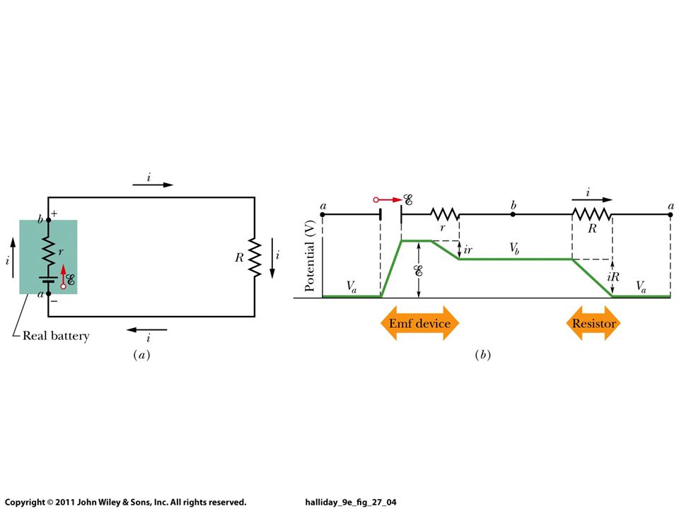
Kirchhoff’s Rules Loop rule: The sum of the changes in potential around a closed loop is zero. Figure Changes in potential around the circuit in (a) are plotted in (b).
 are plotted in (b).")
54
Kirchhoff’s Rules Junction rule: Loop rule:

55
Kirchhoff’s Rules Label each current, including its direction.
Identify unknowns. Apply junction and loop rules; you will need as many independent equations as there are unknowns. Solve the equations, being careful with signs. If the solution for a current is negative, that current is in the opposite direction from the one you have chosen.

56
Kirchhoff’s Rules Using Kirchhoff’s rules.
Calculate the currents I1, I2, and I3 in the three branches of the circuit in the figure. Solution: You will have two loop rules and one junction rule (there are two junctions but they both give the same rule, and only 2 of the 3 possible loop equations are independent). Algebraic manipulation will give I1 = A, I2 = 2.6 A, and I3 = 1.7 A.
. Algebraic manipulation will give I1 = A, I2 = 2.6 A, and I3 = 1.7 A.")
57
Calculate the equivalent
resistance:

58
I I-I1 I1 I1-I2 I-I2 I2 I

59
Solution: Solving the coupled equations and express I1 and I2 in terms of I, R1, R2 and R3

60
Solution:

61
Summary A source of emf transforms energy from some other form to electrical energy. A battery is a source of emf in parallel with an internal resistance. Resistors in series:

62
Summary Resistors in parallel: Kirchhoff’s rules:
Sum of currents entering a junction equals sum of currents leaving it. Total potential difference around closed loop is zero.

63
Summary RC circuit has a characteristic time constant:
Ammeter: measures current. Voltmeter: measures voltage.

Similar presentations


 The circuit diagram below shows.>")


 The circuit diagram.>")

 The circuit diagram.>")


