Download presentation
Presentation is loading. Please wait.

1
Using HEC-1 for Subdivision Runoff Detention Pond Design Stacie Kato April 26, 2004

2
Project Background A detention pond is needed for a developing subdivision in the town of Cicero located in the Jackson Township in Indiana The site is currently a farm field bordered by a fire station, wastewater treatment plant, park, church and residential lands. There is an existing storm sewer that is located north of the site that the detention ponds will be routed to The subdivision will have an average lot size of ¼ acres

3
Project Goal To design two detention ponds on the west side of the site (one in north portion, the other in the south portion) To meet the maximum release rate into the existing storm sewer set by the Town of Cicero To design a storm sewer system to route runoff to the detention ponds To design an emergency spillway channel that will be routed to Wareham’s Pond (northwest of site)
 To meet the maximum release rate into the existing storm sewer set by the Town of Cicero To design a storm sewer system to route runoff to the detention ponds To design an emergency spillway channel that will be routed to Wareham’s Pond (northwest of site)")
4
Model Description HEC-1 generates hydrographs from rainfall data and routes them to reaches and reservoirs Uses the continuity equation (inflow – outflow = change of storage rate), inflow information from design storm hydrograph ordinates, and storage-outflow relationship to calculate flood flow routing
, inflow information from design storm hydrograph ordinates, and storage-outflow relationship to calculate flood flow routing")
5
Methods Determined watershed area from a survey map located from the Hamilton county website Determined basin areas from the slope of site Determined curve number for a residential area with an average lot size of ¼ acres Calculated the time of concentration for each sub basin using a figure from SCS National Engineering Handbook

7
Derived a rainfall intensity equation for the project area and calculated intensities for each sub basin and for the total watershed Calculated the peak flow for each sub basin to determine the pipe diameter for the storm sewer Varied detention pond area and outlet pipe diameter to obtain the best design to meet the maximum release rate into the storm sewer Designed an emergency spillway using the maximum probable storm

8
Results South Detention pond size 0.5 acres and north detention pond size 0.75 acres, both having a 9” diameter outlet pipe

9
South storm sewer system pipe diameter 36” to 42” to 48”, North storm sewer system pipe diameter 36” to 42” 36” pipe 42” pipe 36” pipe 48” pipe Sub basin 1 & 2 runoff Sub basin 1, 2 & 3 runoff North East and West Sub basin runoff North East Sub basin runoff Sub basin 1 runoff To pond

10
Emergency spillway from south detention pond to north detention pond at least 6.4 feet deep, from north detention pond to Wareham’s Pond at least 10.1 feet deep North Detention pond spillway rectangle channel South Detention pond spillway rectangle channel 10 ft 10.1 ft 6.4 ft

11
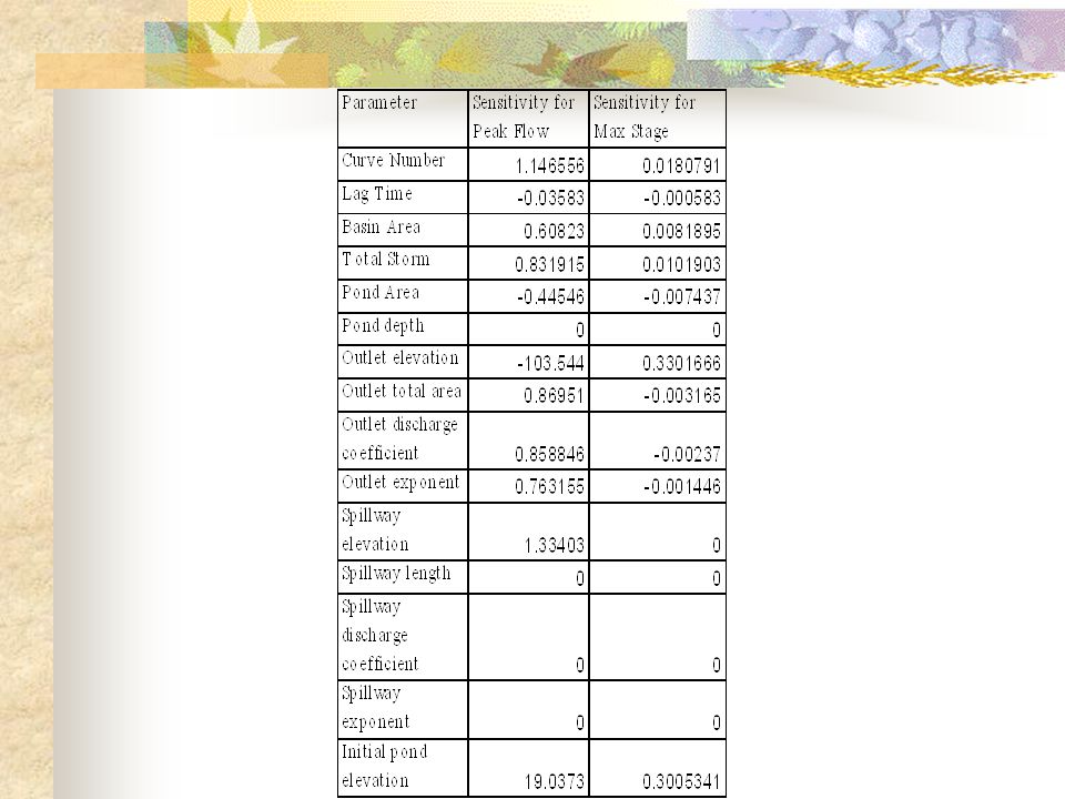
Sensitivity Analysis Most parameters were highly sensitive. Lag time, pond depth, and spillway characteristics were not sensitive. Parameters were not as sensitive for maximum stage output as they were for the peak flow

13
Recommendation for HEC-1 Use HEC-1 is easy to use Model parameters are sensitive to peak flow output Good model to use for designing detention ponds

14
Conclusion Two detention ponds were designed using HEC-1 A storm sewer system was designed An emergency spillway was designed using HEC-1 and FlowMaster

15
Questions?

Similar presentations

>")
 Synthetic unit hydrographs>")


>")


