Download presentation
Presentation is loading. Please wait.

1
Workmanship standards & their application on ESA projects
by Barrie D. Dunn ESA – Estec, 2200 AG Noordwijk, the Netherlands Electronic Materials and Assembly Processes for Space (EMAPS) Workshop Portsmouth University, 17 February 2010
 Workshop. Portsmouth University, 17 February")
2
Workmanship Definition: “the skill with which something was made or done” The product of effort or endeavour Relates very much to the skills of the person Might be a craftsman able to fashion jewellery from precious metals, or An operator on the shop floor who might be assembling spacecraft hardware The base materials from which the item is made must be of suitable composition and texture

3
ESA-approved skills training schools

4
Workmanship Boswell’s Life by Samuel Johnson, published 1766
People thought that everything should be taught from lectures Johnson’s conclusion: chemistry was best taught from lectures, but, concerning workmanship, the teaching of making shoes could only be done by practical training.

5
The Beginning European Space Research Organisation (ESRO) was created in 1962 1968, first succesfully launched satellite (ESRO 2B) This satellite was intended to study cosmic rays and solar X-rays. Estec Materials & Processes Division was expanded in 1969 Took on roles that involved the formation of a dedicated Materials Laboratory Initiation of M&P Specifications Specification tree included standards for: The selection of spacecraft materials and processes (QRM-01) Processes such as soldering (QRM-08). Soldering standard was issued in 1972
 Processes such as soldering (QRM-08). Soldering standard was issued in")
6
Soldering QRM-08 was the first European non-company standard to cover the process of soldering Defined solder alloys and flux The accept-reject workmanship criteria was based on NASA NHB 1973 was the year when ESRO was transformed into the European Space Agency QRM standards were reformatted as ESA-PSS More recently, into the ECSS series of European standards

7
Influence of failure modes on standard requirements
Some early spacecraft electronic assemblies were seen to fail prematurely during environmentally testing ESA Materials Laboratory has developed a large database of failure reports. Topics related to the failures were further researched by means of small studies The results of such works have been influential during the updating of the ESA standards

8
Failure modes A. Terminal pins machined from brass and solder-plated.
Zinc from the brass alloy diffused through the coating to form a thin zinc oxide layer Impossible to wet, even with active solder fluxes Now require a barrier of three microns of either nickel or copper to prevent such zinc diffusion B. Soldering to gold finishes Pasty and very brittle joints Gold-tin intermetallics are notoriously brittle All tin-lead soldering to gold is forbidden unless indium-lead alloys employed

9
Failure modes C. Pure tin electroplating
Tin whiskers growing on circuit boards and tin-plated electronic housing The whiskers had a diameter of 1-6 microns Lengths exceeding 2 mm Carry currents of between 22 and 32 mA before burning out The failure of electronic systems due to whisker growths is expected to be more prevalent following the EU directive to restrict the use of lead (Pb) in electronics
 in electronics.")
10
Schemetic diagram of flat-package leads with bridging and non-bridging whiskers. As the gap between the leads (pitch) gets smaller, the risk of bridging becomes greater. From S. McCormack and S. Mescheter (2009).
 gets smaller, the risk of bridging becomes greater. From S. McCormack and S. Mescheter (2009)..")
11
Risk Map from Monte Carlo-based model using whisker growth time (up to 15.5 years) data from Dunn’s specimen 11 From S. McCormack and S. Mescheter (2009) and Dunn (2006)
 and Dunn (2006).")
12
D. Activated rosin solder flux
Kovar leads on flat packaged component packages broke off due to stress corrosion Standards now limit activated flux to pre-tinning Only non-activated rosin is now permitted for assembly E. Heat-shrinkable plastic sleeves containing solder preforms Observed to cause outgassing (of the retained flux) under vacuum testing Such contamination can cause corona in high voltage situations Almost impossible to visually inspect These devices are now forbidden
 under vacuum testing. Such contamination can cause corona in high voltage situations. Almost impossible to visually inspect. These devices are now forbidden.")
13
Recent studies related to SMT
STUDY TITLE and [reference to be seen in published paper] MAIN FINDINGS Evaluation of the effect of ageing on the cleanability of flux residues [13] SMDs should be cleaned as soon as possible after soldering, but certainly within 24 hours. Cleaning efficiency increases to the fourth power as stand-off height increases. The effect of solder joint geometry on the mechanical fatigue of SMDs [14, in Italian] (mechanical fatigue was made at 20 C and 70 C) Large solder fillets are to be preferred. A stand-off height of 0.2mm is better than either very small or very large stand-offs. Shorter joint lives were noted if test temperature increased from 20 to 70 C. Longer life when tested in vacuum than air. An investigation into Ball Grid Array (BGA) Inspection Techniques [15] (employing various commercially available X-ray equipments) Some minor BGA defects not easily identifiable by all machines, major defects were inspectable. Illustrations used for workmanship standard.
 Large solder fillets are to be preferred. A stand-off height of 0.2mm is better than either very small or very large stand-offs. Shorter joint lives were noted if test temperature increased from 20 to 70 C. Longer life when tested in vacuum than air. An investigation into Ball Grid Array (BGA) Inspection Techniques [15] (employing various commercially available X-ray equipments) Some minor BGA defects not easily identifiable by all machines, major defects were inspectable. Illustrations used for workmanship standard.")
14
Recent studies related to SMT
Assessment of electrically conductive adhesives (ECAs) for joining SMDs to pcbs [16] ECAs not a drop-in replacement for solder paste. Electrical resistance one order of magnitude greater than solder. Ablebond 8175A gave best results. Evaluation of thermally conductive adhesives as staking compounds during the assembly of spacecraft electronics [17] (such adhesives are needed to dissipate heat from component packages) Commercial and space market surveyed, outgassing assessed, samples of compounds under ceramic quad flatpacks thermally cycled with good results, CV-2946 had considerably lower thermal conductivity than manufacturer’s datasheet. Epotek-930 promising. Assessment of reliability of Ball and Column Grid Arrays [18] (exposed to standard thermal cycling environments) Columns had best fatigue life, Thermount improved all fatigue lives, epoxy underfill created early failures. Dye-penetrant test method developed and workmanship illustrations generated. Impact of cracking beneath solder pads in pcb laminates on reliability of BGAs [19] Low temperature extreme during thermal cycling is main cause of laminate cracking beneath solder pads to ceramic BGAs. Such cracks may improve fatigue life.
 for joining SMDs to pcbs [16] ECAs not a drop-in replacement for solder paste. Electrical resistance one order of magnitude greater than solder. Ablebond 8175A gave best results. Evaluation of thermally conductive adhesives as staking compounds during the assembly of spacecraft electronics [17] (such adhesives are needed to dissipate heat from component packages) Commercial and space market surveyed, outgassing assessed, samples of compounds under ceramic quad flatpacks thermally cycled with good results, CV-2946 had considerably lower thermal conductivity than manufacturer’s datasheet. Epotek-930 promising. Assessment of reliability of Ball and Column Grid Arrays [18] (exposed to standard thermal cycling environments) Columns had best fatigue life, Thermount improved all fatigue lives, epoxy underfill created early failures. Dye-penetrant test method developed and workmanship illustrations generated. Impact of cracking beneath solder pads in pcb laminates on reliability of BGAs [19] Low temperature extreme during thermal cycling is main cause of laminate cracking beneath solder pads to ceramic BGAs. Such cracks may improve fatigue life.")
15
SMT Standard ECSS-Q-STD-70-38
The ECSS standard for Surface Mount Technology issued Oct 2007 Delays were inevitable as the results of our studies were awaited Unacceptable to select SMD packages which cannot be reworked Needed to evaluate methods for the repair of area grid arrays Necessary to address the Standard’s cleanliness test methods Contains many workmanship illustrations Micrographs after the dye penetrant testing of BGAs or check electrically.

16
Approval of processes for ESA projects
Each supplier will appoint a Materials & Processes (M&P) manager (ECSS-Q-ST-70B) This person will be the contact with ESA’s M&P Division One important task: supplier to follow the steps needed to gain approval for the materials, and manufacturing processses The following nomenclature is used by ESA and ECSS Materials are Validated Mechanical parts are Qualified Processes are Verified Operators and inspectors of critical processes are Trained, Certified and Monitored.
 manager (ECSS-Q-ST-70B) This person will be the contact with ESA’s M&P Division. One important task: supplier to follow the steps needed to gain approval for the materials, and manufacturing processses. The following nomenclature is used by ESA and ECSS. Materials are Validated. Mechanical parts are Qualified. Processes are Verified. Operators and inspectors of critical processes are Trained, Certified and Monitored.")
17
Processes are controlled on each ESA project by means of the project’s Declared Processes List
Hand soldering of leaded components using plated through hole technology (Manual Soldering standard) will only require that the operator is Trained and Certified Reworking of solder joints is permitted, but it can reduce the reliability of multilayer boards if repeated heat is applied to the joints.
 will only require that the operator is Trained and Certified. Reworking of solder joints is permitted, but it can reduce the reliability of multilayer boards if repeated heat is applied to the joints.")
19
Only operator certification is needed for:
Standard repair activities on pcb assemblies Semi-rigid cable assembly, crimping and wire wrapping Crimping and wire wrapping (now seldom selected) are also controlled by the metallographic examination of in-line samples. The microsections are then compared against defined accept/reject workmanship samples
 are also controlled by the metallographic examination of in-line samples. The microsections are then compared against defined accept/reject workmanship samples.")
20
Surface mount assembly processes are different
They require a very precise “Verification programme” in order to achieve ESA-approval. It is the machine, rather than the operator which is assessed. Methodology for gaining SMT approval (i.e. approval per project by means of the Declared Processes List) written request for process verification generation of a Process Identification Document (PID) Manufacture of Technology Samples (conform to ECSS workmanship standards) An audit of the processing line Performing the Verification Programme Visual, electrical and metallographic tests to assess acceptance
 written request for process verification. generation of a Process Identification Document (PID) Manufacture of Technology Samples (conform to ECSS workmanship standards) An audit of the processing line. Performing the Verification Programme. Visual, electrical and metallographic tests to assess acceptance.")
21
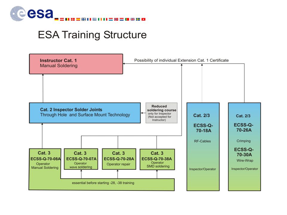
ESA-approved skills training schools
Initial training made at TRW following NASA courses (1972) First ESA skills training school in Münich (1979) ESA now supports six schools situated in Germany, UK, France, Italy and Denmark They cater for training in almost all the languages of ESA’s Member States Attendees to the schools’ courses gain certificates at operator (Category 3), inspector (Cat. 2) and instructor levels (Cat. 1) Certificates are issued, based on the passing of both written and practical examinations.
 First ESA skills training school in Münich (1979) ESA now supports six schools situated in Germany, UK, France, Italy and Denmark. They cater for training in almost all the languages of ESA’s Member States. Attendees to the schools’ courses gain certificates at operator (Category 3), inspector (Cat. 2) and instructor levels (Cat. 1) Certificates are issued, based on the passing of both written and practical examinations.")
22
The Managers of each school attend an annual meeting which reviews:
Changes to the ECSS standards Course material and revisions Technology advancements results of ESA studies Each school maintains a similar level of examination, using both the same questions template and the same printed circuit board and component kit Attendance to the ESA Skills Training Schools remains in the region of 800 to 1000 students per year. Envisaged that a similar number of persons also attend courses that are delivered by Category 1 instructors, within the larger space companies

24
Coordination with NASA on workmanship issues
ESA staff and instructors trained at NASA’s schools at GSFC and JPL ESA participates to NASA Workmanship Technical Committee (WTC) ESA/NASA studies presented at past WTC meetings The Bilateral Safety and Product Assurance Baseline for International Space Station contains a traceability matrix Agreement that the NASA requirements for materials and processes (SSP-30233, rev. C) are equivalent to the ESA requirements for M&P as were specified in PSS-01-70 No formal “meets or exceeds” exercise has been performed to equate NASA and ESA workmanship standards ESA and NASA standards listed in Table 2 have very similar requirements as is always the case, the differences are in the details. NASA has a well-developed Conformal Coating and Staking standard (NAS (3J-1)) ESA is not committed to utilising the Space Addendum 1 attached to IPC J-STD-001
 ESA/NASA studies presented at past WTC meetings. The Bilateral Safety and Product Assurance Baseline for International Space Station contains a traceability matrix. Agreement that the NASA requirements for materials and processes (SSP-30233, rev. C) are equivalent to the ESA requirements for M&P as were specified in PSS No formal meets or exceeds exercise has been performed to equate NASA and ESA workmanship standards. ESA and NASA standards listed in Table 2 have very similar requirements. as is always the case, the differences are in the details. NASA has a well-developed Conformal Coating and Staking standard (NAS (3J-1)) ESA is not committed to utilising the Space Addendum 1 attached to IPC J-STD-001.")
25
Table. Similar ESA and NASA Workmanship Standards
Process Name ESA-ECSS ref. Number NASA-STD ref. Number Machine, wave soldering Q-70-07 Detail in Manual soldering Q-70-08 8739.3 RF semi-rigid soldering coax cables Q-70-18 and Crimping Q-70-26 8739.4 Repair and modification Q-70-28 Wire wrapping Q-70-30 Surface-mount Technology Q-70-38 8739.2 Optical Fibres Q-70-51 8739.5

26
Conclusion Small studies are essential in order to understand the chemistry and metallurgy of electrical interconnections. A good understanding of the process is needed before any workmanship standards can be generated. The training of operators and inspectors related to spacecraft assembly processes is important and their work needs to be continually reviewed. Major workmanship defects could reduce the operational life of a space system and they need to be repaired (or reworked) using verified processes. Most minor and cosmetic defects do not warrant repair (or rework) and more harm than good often results from unnecessary rework. I would finally like to re-iterate the sentiments of John Maristch (NASA-GSFC). As our space projects become more global, we should be working more closely with out international partners (ESA, NASA, NASDA, CNES, CSA, etc.). This might reduce the disparity between these Agencies regarding workmanship requirements, suppliers’ processes verification, and materials selection.
 using verified processes. Most minor and cosmetic defects do not warrant repair (or rework) and more harm than good often results from unnecessary rework. I would finally like to re-iterate the sentiments of John Maristch (NASA-GSFC). As our space projects become more global, we should be working more closely with out international partners (ESA, NASA, NASDA, CNES, CSA, etc.). This might reduce the disparity between these Agencies regarding workmanship requirements, suppliers’ processes verification, and materials selection.")
27
Acknowledgements I would like to thank my colleagues Dave Adams and Gianni Corocher for their patience in the archiving of workmanship photographs and for the use of their photomicrographs. To Carole Villette, who has tirelessly assisted as a key person in the working groups assigned to each ECSS Workmanship Standard.

28
Additional information
Many of the publications referenced can be seen on

Similar presentations


 Working Group Barrie Dunn May 2011.>")


